THÈSE
En vue de l’obtention du
DOCTORAT DE L’UNIVERSITÉ DE TOULOUSE
Délivré par l'Université Toulouse 3 - Paul Sabatier
Présentée et soutenue par
Jean-Luc HAK
Le 18 juillet 2019
Ecole doctorale : EDMITT - Ecole Doctorale Mathématiques, Informatique et
Télécommunications de Toulouse
Spécialité : Informatique et Télécommunications
Unité de recherche :
IRIT : Institut de Recherche en Informatique de Toulouse
Thèse dirigée par
Philippe PALANQUE et Marco WINCKLER
Jury
M. Jean VANDERDONCKT, Rapporteur
M. Philippe PALANQUE, Co-directeur de thèse M. Marco WINCKLER, Co-directeur de thèse Mme Regina BERNHAUPT,
Engineering annotations for supporting the design process of
interactive systems: A model-based approach and a tool suite
de systèmes interactifs: une approche basée modèle et outillée
Ingénierie des annotations pour le support de processus de conception
Présidente du jury
ii
Acknowledgements ... ix
Résumé de la thèse ... xi
Abstract ... xii
Chapter 1. Introduction ... 1
Chapter 2. State of the art of development process ... 7
2.1. Introduction to development process for interactive systems ... 7
2.2. Overview of the development processes ... 8
2.2.1. Waterfall process (Royce, W. W., 1970) ... 8
2.2.2. V-model (McDermid & Ripken, 1983) ... 9
2.2.3. The Nabla model (Kolski, 1998) ... 10
2.2.4. Spiral model (Boehm, 1986) ... 11
2.2.5. Rational Unified Process (Kruchten, 2004) ... 11
2.2.6. AGILES methods (Cockburn, 2002) ... 12
2.2.7. Star model (Hartson, 1989) ... 14
2.2.8. The layered development process model (Curtis, 1994) ... 15
2.2.9. The Object-Oriented User Interface (OOUI) design process (Collins, 1995) ... 15
2.2.10. The Iterative-cyclic process (Rauterberg, 1992) ... 15
2.2.11. User-centered System Design (Gulliksen, 2003) ... 16
2.2.12. The Usage-Centered Design (Constantine & Lockwood, 2002) ... 18
2.2.13. The ISO User-Centered Design (UCD) process ... 19
2.2.13.1 Presentation of the tasks of the UCD ... 20
2.3. Synthetic analysis of the development processes ... 21
2.4. Conclusion ... 22
Chapter 3. Analysis of annotations ... 25
3.1. Introduction ... 25
3.2. Nature of annotations ... 25
3.3. Annotations classes and dimensions ... 27
3.4. Studies of annotations in text documents ... 28
3.4.1. Presentation of the roles involved in the design process ... 28
3.4.2. Uses of annotations ... 29
3.4.3. Synthesis of annotations definitions ... 33
3.4.4. The case of freeform annotations ... 34
3.5. Other uses of annotations on digital artefacts ... 35
iii
3.6.1. The Core of the annotation ... 37
3.6.2. The Metadata of the annotation ... 38
3.6.3. The Goal of the annotation ... 38
3.7. Conclusions ... 38
Chapter 4. Overview of tools supporting annotations and of prototyping tools ... 41
4.1. Introduction ... 41
4.2. Review of annotation tools ... 42
4.2.1. Selection of tools ... 42
4.2.2. Criteria used for the analysis of annotations tools ... 42
4.2.3. Results of the review of annotation support ... 43
4.2.3.1 Targeting support ... 43
4.2.3.2 Temporal evolution of artefacts ... 43
4.2.3.3 Semantic of annotations ... 44
4.2.3.4 Annotation management ... 44
4.2.3.5 Collaborative support ... 44
4.3. Review of prototyping tools ... 45
4.3.1. Selection of tools ... 45
4.3.2. Criteria used for analyzing prototyping tools ... 46
4.3.3. Source of information collected ... 46
4.3.4. Results of the review of prototyping tools ... 46
4.3.4.1 Features provided by prototyping tools for the specification and the design ... 46
4.3.4.2 Version control features provided by prototyping tools ... 47
4.3.5. Results of the review of annotations support in prototyping tools ... 47
4.3.5.1 Creation of annotations... 47
4.3.5.2 Targeting support ... 48
4.3.5.3 Temporal evolution of artefacts ... 48
4.3.5.4 Semantic of annotations ... 48
4.3.5.5 Annotation management ... 49
4.3.5.6 Collaborative support ... 49
4.3.6. Findings on prototyping tools... 50
4.3.6.1 The specification of the prototype is limited to the UI ... 50
4.3.6.2 Uses of annotations in prototyping tools ... 50
4.3.6.3 Targeting support in prototyping tools are limited to their tools ... 50
iv
4.4. Other findings concerning both annotating and prototyping tools ... 52
4.4.1. Tasks for supporting annotations ... 52
4.4.2. Creation of annotations... 53
4.4.3. Navigation between the annotation and the target ... 53
4.4.4. Dependence of the annotation on its artefact without acknowledging its evolution ... 53
4.4.5. Lack of support for the evolution of the context of the annotation ... 53
4.4.6. A few features dedicated to the management of the lifecycle of annotations ... 54
4.4.7. No support for documenting a custom semantic for annotations... 54
4.4.8. Limits of annotations support for an environment that includes many types of artefacts 54 4.4.9. Limits of prototyping tools for the support of the traceability of the design ... 55
4.5. Conclusions ... 57
Chapter 5. Management and usage of annotations in the UCD process ... 59
5.1. Introduction ... 59
5.2. Artefacts and annotations lifecycle ... 59
5.2.1. Lifecycle of design artefact within the design process ... 59
5.2.2. Lifecycle of annotation within the design process ... 60
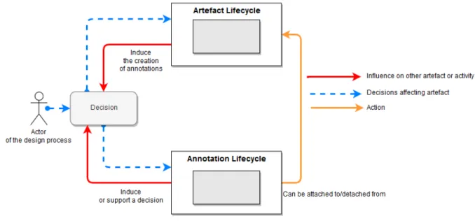
5.2.3. Relationship between the annotations and design artefacts: a reciprocal influence and repercussions... 61
5.3. Usage of annotations during the UCD process ... 63
5.3.1. Annotations for connecting models of the interactive system ... 64
5.3.1.1 Usage of the targeting properties of annotations to connect models ... 64
5.3.1.2 Necessity to formalize artefacts within the project workspace ... 64
5.3.2. Annotations for assisting stakeholders in their activities ... 65
5.4. Management of the relationship of an annotation and its targets... 65
5.4.1. Management of the targets based on the relevance of the annotation ... 65
5.4.2. Targeting support of versioned files and versioning of annotations ... 66
5.5. Conclusion ... 68
Chapter 6. Model-based approach for describing annotations ... 69
6.1. Introduction ... 69
6.2. Towards an Annotation Models for Artefacts used to build interactive systems ... 70
6.2.1. Features inherited from the Web Annotation Data Model ... 70
6.2.2. Specificities of the annotations on artefacts of the design of interactive systems ... 70
6.2.3. Description of the annotation model ... 72
v
6.4. Extensibility of the model ... 83
6.5. Conclusion ... 84
Chapter 7. An architecture for integrating annotations made on diverse artefacts ... 87
7.1. Introduction ... 87
7.2. Inner of the architecture ... 87
7.3. Presentation of the file repository for managing annotations of the project ... 89
7.4. Architecture of the annotation plug-in ... 90
7.4.1. Integration of the plugin for its support in a new editor and its artefacts ... 92
7.4.2. Current status of the integration of the plugin in editors and their artefacts ... 96
7.5. ARMADILLO: An annotation tool support for managing annotations of a project ... 96
7.5.1. Description of the ARMADILLO tool support ... 96
7.5.2. Architecture and extensibility of the ARMADILLO tool support ... 97
7.6. Conclusion ... 99
Chapter 8. The PANDA ecosystem ... 101
8.1. Introduction ... 101
8.2. The PANDA prototyping tool ... 101
8.2.1. Overview of PANDA ... 101
8.2.2. Integration of the annotations plugin in PANDA ... 102
8.3. Case study ... 104
8.3.1. Informal presentation of the case study ... 104
8.3.2. Automated test of prototypes with a scenario ... 104
8.4. Conclusions ... 108
Chapter 9. Integrated view of annotations on CIRCUS ... 109
9.1. Introduction ... 109
9.2. The different models and design artefacts representing the interactive system ... 110
9.2.1. Annotation using ARMADILLO ... 110
9.2.2. Prototypes using PANDA ... 110
9.2.3. Task models using HAMSTERS ... 111
9.2.4. Dialog models using ICO ... 111
9.3. Case study ... 111
9.3.1. Informal presentation of the case study ... 111
9.3.2. The various artefacts of the WXR project ... 112
9.3.3. Annotation of the prototype artefact of the case study ... 115
vi
10.1. Introduction ... 121
10.2. Overview of the e-CitizTM framework ... 121
10.3. The “eazlyTM” project ... 122
10.3.1. Overview of eazlyTM ... 122
10.3.1.1 The evolution of the design process ... 122
10.3.2. Using of eazlyTM as a prototyping tool ... 127
10.3.2.1 Users of the eazly StudioTM... 128
10.3.2.2 The different models of the eazlyTM framework ... 128
10.3.3. Annotation support for collaborating over the design ... 129
10.3.3.1 Motivations for adding annotations support in the eazly StudioTM ... 129
10.3.3.2 Early prototypes of the annotation support in the eazly StudioTM ... 129
10.3.3.3 Integration of the annotations in the eazly StudioTM ... 133
10.3.4. Versioning of the evolutions to ensure the integrity of the application ... 135
10.3.4.1 Challenges imposed by the e-CitizTM design process with eazlyTM and its double iterations loop ... 135
10.3.4.2 The proposed solutions to tackle the issues of the design choices made for eazlyTM ... 136
10.3.5. Traceability of the evolutions of the design through the iterations ... 137
10.4. Conclusions ... 137
Chapter 11. Conclusions and Future Work ... 141
List of publications ... 145
List of figures ... 147
List of table ... 151
Annex 1. List of annotation tools examined for the state of the art ... 153
Annex 2. List of prototyping tools examined for the state of the art... 155
Annex 3. Synthesis of the analysis of annotation support ... 157
Annex 4. XSD of the annotation file ... 159
Annex 5. XSD of the PANDA dialog file ... 167
Annex 6. XSD of the PANDA presentation file ... 169
Annex 7. Presentation of the PANDA ecosystem ... 171
7.1. Introduction ... 171
7.2. User interface models described in the PANDA ecosystem ... 171
7.3. The PANDA ecosystem: a framework for supporting traceability of the design process ... 173
vii
7.3.4. Combining the modules ... 177
7.3.5. Integration of the modules of the PANDA ecosystem within the UCD process ... 180
7.4. Creating and previewing a PANDA prototype ... 182
7.4.1. Creating a prototype using PANDA ... 182
7.4.2. Previewing the PANDA prototype ... 186
Annex 8. Presentation of the e-CitizTM framework ... 191
8.1. Introduction ... 191
8.2. Overview of the e-CitizTM framework ... 191
8.2.1. The actors of the e-CitizTM framework ... 192
8.2.2. The iterative design process for the design of an e-CitizTM application ... 192
8.2.3. The development of the e-CitizTM application ... 192
8.3. The different models of the application ... 195
8.3.1. The e-CitizTM model ... 195
8.3.2. The user data structure ... 195
8.4. Conclusions on the e-CitizTM framework ... 196
8.4.1. The lack of the e-CitizTM framework ... 196
8.4.2. The “Process 2.0” project ... 197
8.4.3. Toward the “eazlyTM” project ... 200
ix my PhD dissertation.
Thanks to Softeam for funding this PhD thesis and for allowing me to manage my work schedule with the IRIT with such flexibility.
Thanks to Marco for accepting me as his PhD student as well as his support and his availability throughout this PhD thesis despite all his works in parallel.
Thanks to Olivier, Cyril, Nicolas, and Laurent for supervising me during the development of eazly as well as all the R&D team, Frédéric, and Jérôme for welcoming me.
Thanks to Eric for his help during the successive developments of PANDA and ARMADILLO and thanks to Cyril, Laurent, Ali, Monia, Nicolas and Abdennacer for helping me develop eazly.
Thanks to everyone within the ICS team for their help and for keeping a good working atmosphere both during and after working hour.
Lastly, I would like to thank all my family for their support through all these years of study and for the years to come.
xi
des activités de ce processus et plusieurs choix de conceptions sont effectués afin de converger vers une solution répondant à la fois aux besoins des utilisateurs et aux exigences. Pour atteindre cette solution, de nombreux artefacts sont produits, utilisés et révisés par les différents intervenants du processus. Afin de communiquer sur des points particuliers d’un artefact, collaborer dans son élaboration ou tout simplement rajouter des informations complémentaires, des annotations peuvent être créés sur ces artefacts. En fonction des annotations et de leurs contenus, certains artefacts peuvent par la suite être amenés à évoluer, reflétant ainsi l’influence des annotations sur ces artefacts et donc leurs influences sur le projet de manière globale. Il est donc possible de considérer les annotations comme un outil versatile jouant un rôle non négligeable dans le processus de conception. Néanmoins, plusieurs problèmes peuvent être identifiés concernant l’intégration des annotations au sein des activités d’un processus de conception de système interactifs. Premièrement, le rôle des annotations n’est pas clairement défini dans les différents processus de conceptions. En effet, bien qu’on observe l’usage omniprésent des annotations lors de la conception de systèmes interactif, les processus de conception actuels n’expliquent pas comment les relier aux tâches à accomplir et les artefacts à produire. Deuxièmement, une annotation peut concerner plusieurs artefacts car chacun modélise des points de vue complémentaires du système interactif. Néanmoins, la multiplicité des types d'artefacts et des outils pour la création de ces artefacts pose un problème car chaque outil qui offre la possibilité de créer des annotations propose son propre modèle d’annotation. Ce modèle est généralement restreint à un type d’artefact donné : celui manipulé par l’outil. Ceci implique que les annotations d’un projet sont éparpillées par lot et que chaque lot d’annotations est fermé à un seul type d’artefact.
Cette thèse s'appuie sur une analyse des annotations et des pratiques liées aux annotations ainsi que sur la recommandation "Web Annotation Data Model" du W3C pour proposer un modèle d'annotation et une architecture logicielle permettant de centraliser les annotations d'un projet et d'intégrer ces annotations dans divers types d'outils et d’artefacts. Ce modèle d’annotation et cette architecture logicielle a été appliquée dans trois études de cas différents afin d’explorer différentes intégrations possibles au sein d’un processus de conception. La première étude de cas démontre l’intégration et la personnalisation d’annotations au sein d’un outil de prototypage. La seconde étude de cas s’attarde sur la présentation d’un outil permettant de consulter dans une vue unique l’ensemble des annotations créés sur différents artefacts et sur les différents modèles d’un projet. La troisième étude de cas illustre une intégration des annotations dans un environnement industriel comprenant des outils et un processus de conception existant.
Ainsi, ces contributions autour des annotations servent de base pour la réalisation de travaux complémentaires tels que l'utilisation d'annotations pour structurer et connecter les différents modèles d’un système interactif, l'utilisation d'annotations en tant que ressource pour les processus de prises de décisions, et l’utilisation d'annotations pour étudier la traçabilité de l’évolution d’un système interactif. En effet, en reliant les artefacts entre eux en utilisant les annotations et en justifiant les choix de conceptions avec des annotations, il serait possible d’assurer la traçabilité des différents choix de design effectués au cours d’un projet ainsi que la traçabilité de l’impact de ces différents choix sur les artefacts.
MOTS-CLES : Processus de conception de système interactifs, Annotations, Techniques de
prototypage, Conception Centrée Utilisateur, Gestion et évolution des prototypes, Outil de support à la conception de système interactifs
xii
of this process and several design choices are made to converge to a solution that meets both user needs and requirements. To achieve this solution, many artifacts are produced, used and reviewed by the various stakeholders of the process. In order to communicate on particular points of an artifact, to collaborate in its elaboration or simply to add additional information, annotations can be created on these artifacts. Depending on the annotations and their contents, some artefacts may subsequently evolve, thus reflecting the influence of annotations on these artifacts and therefore reflecting their influence on the project. Thus, it is possible to consider annotations as a versatile tool playing a significant role in the design process.
Nevertheless, several issues can be identified regarding the integration of annotations within the activities of the design process of interactive systems. First, the role of annotations is not clearly defined in the different design processes. While there is a widespread and a ubiquitous use of annotations in the design of interactive systems, current design processes do not address how to relate them to the tasks to be performed and the artifacts to be produced. Secondly, an annotation can be related to several artifacts as each models are giving a complementary representation of the interactive system. However, the multiplicity of artifact types and tools for creating these artifacts is a problem since each tool that provide features for annotations implements their own annotation model. These models are usually restricted to one type of artifact: the one handled by the tool. This implies that the annotations produced within a project are scattered by sets and that each these annotation set is closed to a single type of artifact.
This PhD thesis is based on an analysis of annotations and their uses as well as on the W3C “Web Annotation Data Model” recommendation to propose an annotation model and an architecture to centralize the annotations of a project. This architecture also allows to include the annotations support on various tools and type of artifacts. This contribution has been applied on three different case studies to explore the possible integrations of annotations within a design process. The first case study demonstrates the integration and customization of annotations within a prototyping tool. The second case study focuses on the presentation of a tool allowing to consult in a single view all the annotations created on different artefacts and on different models of a project. The third case study illustrates an integration of annotations into an industrial environment that includes existing tools and an existing design process.
Thus, these contributions around annotations are used as a basis for the realization of complementary works such as the use of annotations to structure and connect the different models of an interactive system, the use of annotations as a resource for the decisions making processes, and the use of annotations to study the traceability of the evolution of an interactive system. Indeed, by linking the artifacts to each other using annotations and justifying the choice of designs with annotations, it would be possible to ensure the traceability of the different design choices made during a project as well as the traceability of the impact of these different choices on the artifacts.
KEYWORDS: Design of interactive systems, Annotations, Prototyping techniques, User Centered
1
Chapter 1. Introduction
Annotations always played an important role in human History as a mean to add complementary information to documents. Since late Antiquity, annotations in the margin of documents are testimonies to a critical and scientific way of dealing with texts: versions are compared, passages that seem to be corrupted are marked, contrasting opinions are highlighted, confronted and discussed [1]. Figure 1-1 shows two Early Renaissance documents containing annotations: a) annotations left by an anonymous scholar (a student, a school teacher or a professional translator) on an edition of Homer’s Odyssey printed in 1504 (probably) for studying and preparing a future translation of the text [2]; and, b) annotations left by Leonardo da Vinci to explain the design of his water-lifting machine (1481) [3]. As we shall see, annotations might be written by the creator of the document at the time of writing or added later on by other people. Annotations have been demonstrated useful tools for communication; they can be used to explain an idea and also collect feedback from the readers. For that they are a commonplace in text documents1. It is interesting to notice that annotations might contain information
aimed to correct and/or improve a piece of work.
a) Annotated 1504 edition of Homer’s Odyssey b) Leonard da Vinci on “Water Lifting Devices” (1481) Figure 1-1 Examples in Early Renaissance documents showing the use of annotations for explain a design/idea
However, annotations are not an exclusivity of text documents, we might found annotations associated to other types of documents including specifications used for building interactive systems [4; 5; 6]. Indeed, annotations are frequently found as a mean to complete the description of mockup prototypes with information that could not be specified otherwise due to the inner nature of the prototype itself. Figure 1-2 illustrates a paper-based mock-up featuring annotations to describe the nature of the graphical components and the expected behavior (dialog between windows) for a mini-game prototype.
2 Figure 1-2 Prototype of a mini-game
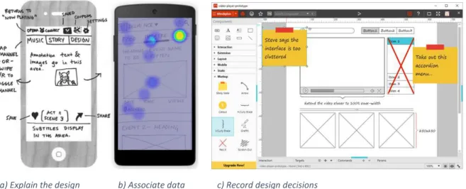
Figure 1-3 illustrates a few uses of annotations on prototypes of interactive systems, including explaining the design (Figure 1-3.a), associating data available from other sources (in the example results of a usability evaluation featuring a heat map generated by eye-tracking) (Figure 1-3.b), and record design decisions such as opinions/preferences and instructions on how to improve the design (Figure 1-3.c). As we shall see, annotations might assume many forms (such as text, sketching, highlighting, etc.) making this a suitable mechanism to provide complimentary information with multiple uses.
a) Explain the design b) Associate data c) Record design decisions
Figure 1-3 Three example of the use of annotations on prototype
Empirical observations have demonstrated that development teams often make an extensive use of annotations as a communication support. The study performed by Gutierrez et al. [5] pointed out that annotations are used by members of development teams to: record the results of discussion including decisions and upcoming tasks, communicate and inform other team members of the work done, gather internal and external feedback on artefacts stored in the workspace, conduct usability evaluations by documenting information and by recording conversation between design teams and UX experts, justify design choices, and document the design choices by describing them retrospectively.
3
Whilst annotations might be available in many integrated development environment (IDE), the study about the use of annotations during the development process of interactive systems is quite recent and many research question are still pending for example:
- What is the current state of the knowledge about tools supporting the use of annotations for building interactive systems?
- What are the attributes that make annotations essential for the design of interactive systems? - How annotations are connected to the diverse artefacts produced along the development
process?
- In which phases of the development process should annotations be employed? - How annotations evolve along the phases of the development process?
In this PhD thesis, we investigate the role played by annotations during the development process of interactive systems. Given the associative nature of annotations, it is quite natural to consider annotations as a possible design solution to the problem of tracing design decisions to artefacts. Our ultimate goals with this work on annotations are:
i) To investigate a systematic strategy for connecting ideas and design decisions to the multiple artefacts used to build interactive systems,
ii) To promote the development of tools helping the development team to have a coherent view of the decisions made along the development process of interactive system. The foundations of our proposal follow some premises:
- Annotations are formalized otherwise we cannot build tools to handle them in computer-aided design tools for building user interfaces;
- Annotations are considered as an artefact on its own right. We use the term artefact to refer pieces of work that contribute to the development of an interactive system, for example prototypes, models, specifications, etc.
- Annotations are dynamic and subject to change/evolve along the development process in iterative cycles.
We suggest that annotations can be connected to diverse type of artefacts. However, this PhD thesis focus on annotations made over user interface prototypes. In order to illustrate the connectivity of annotations to other artefacts, we extend the study to task models and dialog models and we show how annotations can be used to create a coherent view. We assume that the contents of annotations might affect the evolution of the prototypes and artefacts used to build interactive systems. If so, we should be able to trace design decisions by following the evolution of artefacts and the annotations connected to them. The scientific questions addressed in the PhD thesis are also relevant for the industry and have many practical applications. This manuscript is organized in eleven chapters as illustrated in the Figure 1-4.
4
Figure 1-4 Chapters of the PhD thesis
The Chapter 1 refers to this introduction and the Chapter 11 presents the conclusions and future work. The other chapters are organized in three main parts, as follows:
STATE OF THE ART
The Chapter 2 presents an overview of the development processes for interactive systems.
The Chapter 3 revises the literature on annotations, starting with early works annotations on text documents and concluding with the most recent attempts of the W3C to create a standard for annotations of electronic documents.
The Chapter 4 presents a comprehensive analysis of existing tools supporting annotations and prototyping activities.
CONTRIBUTIONS
The Chapter 5 specifies the life cycle of annotations within a user-centered design process. This chapter proposes a micro process (i.e. a process that can be run as a small activity inside a development process) for the management of individual annotations (including creation, publication, validation, updating, disposal, and archival) and the co-evolution of annotations and artefacts along the development process.
The Chapter 6 proposes a structured model for annotations. The goal of this model is to formalize annotations within the context of the design process of interactive systems while taking into account the specificities of annotations such as the targeting of artefacts, the alternative representation for annotations, and their corresponding lifecycle.
5
The Chapter 7 presents an architecture for integrating annotations made on diverse artefacts. This architecture is illustrated with a tool support called ARMADILLO designed for the management of annotations. This tool is compliant with our annotation model described in the Chapter 6. The ARMADILLO tool encompass a project workspace featuring several type of artefacts and their respective editors. This chapter shows how to create and to edit annotations as independent entities, which can ultimately be connected to other design artefacts such as user interface prototypes using ARMADILLO.
CASE STUDIES
The Chapter 8 presents a case study of annotation of prototypes. It illustrates the user interface of a flight booking system. In this chapter we introduce the PANDA ecosystem, which is a dedicated tool for prototyping user interfaces supporting annotations. PANDA is used here to illustrate the annotation model presented at the Chapter 6. We demonstrated how annotations created directly on PANDA are inserted into the ARMADILLO annotation system. We also demonstrate how ARMADILLO helps, thanks to the annotations, to track the evolution of prototypes build using PANDA.
The Chapter 9 is aimed at showing how annotations created over diverse artefacts can be handled to provide an integrated view of the project. For that, we introduce a case study around the CIRCUS framework. The case study illustrate an application called “Weather Radar” (WXR) and the corresponding specifications built with models available in the CIRCUS framework for prototyping the user interface (PANDA), the users’ tasks (HAMSTERS), and the behavior of the application (PETSHOP). In this case study, the annotation model is used to structure the design artefacts of a project by binding them together and by featuring annotations on several design artefacts.
The Chapter 10 demonstrates the transfer of our ideas to the industry. This chapter describes how some of our contributions were applied in a commercial tool called eazlyTM developed within Softeam
Software Business Unit of the Softeam Group which co-funded this PhD thesis under a CIFRE scholarship (ANRT co-funding). This tool is an editor that allows its users to edit e-service applications after their deployments on production servers. The main interest of this case study is to emphasize on the consequences and the tracking of the evolution of an interactive system after its deployment. Some of the scientific contributions have been subject of publications (2 international journals, 2 full papers in international conferences with peer reviewing, and 1 late-breaking results in an international conference with peer reviewing). These publications are duly cited along the chapter.
7
Chapter 2. State of the art of development process
Summary
This chapter provides an overview of the development process for interactive systems. It presents a view at glance of the most referenced development process, giving a particular attention to the ISO standard User-Centered Design process. This chapter provides a synthetic analysis of the development process with respect to the identification of the actors of the processes, the involvements of the client and end-users, the iterative processes aspect, and the artefacts produced during the process. This analysis is mainly focused on the macro development processes. The micro process describing how annotations intervene along the development process is given at Chapter 5.
2.1. Introduction to development process for interactive systems
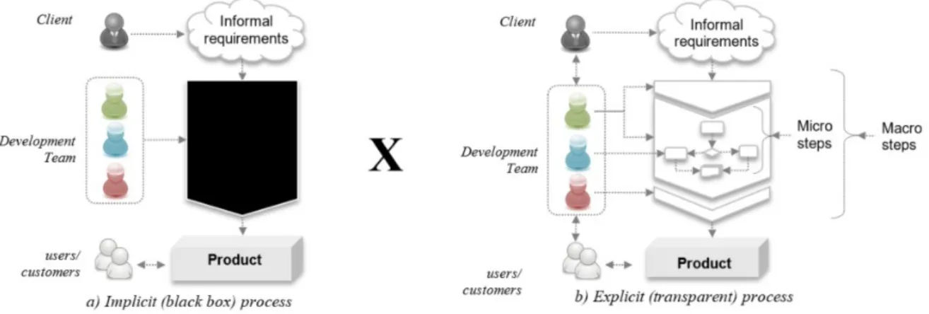
The development of interactive systems requires a plan and a systematic approach. A development process can be explained as a kind of black box where only the input (i.e. the requirements) and the output (i.e. the product delivered) are known, as illustrated by Figure 2-1.a. However, a black box process does not inform the steps that lead from requirements to the final product thus preventing a systematic analysis of problems and reducing the possibilities of a transparent coordinating the activities among members of the development team; as a consequence, it is difficult to monitor the progress of the development and when the product appears at the end of the process it is often too late to care about the quality. A black box process is even worse for dealing with software products because that development process often starts with informal requirements raised by clients who are not able to translate their perception of the business world into precise requirements [3]. In the beginning of the process, software requirements are often informal, incomplete, they can be sometimes contradictory or not reflecting the customers’ needs. In a black box process, there is no guidance for revising initial requirements or to introduce new requirements identified along the way. Conversely, when an explicit process is in place we can see through complexity: activities can be decomposed into smaller and more manageable steps, members of the development team know the steps which help to coordinate their activities, introduction of errors can be prevented by applying solutions to known problems in a systematic way, and quality can be checked at every step of the process (as illustrated by Figure 2-1.b). Moreover, progress can be monitored and communicated to clients who can help to clarify, complete, refine and possibly revise requirements that might change during the process, thus increasing the chances that the final product meets the customers’ expectations. Thus, whilst is tempting to deal with complexity in software development by separating the product (what is visible to the client/costumers) from processes (how this quality products can be achieved), we should recognize that product and processes are intermingled because it is by controlling processes that developers can inject the required qualities of products, to reduce time to market and to manage development costs. Therefore, it is clear that to achieve quality and software correctness we have to go inside the black box, describe steps into details and make sure that the process is structured in such a way that makes the development systematic and less suitable to include errors.
8
Figure 2-1 Overview of development process as an implicit black box (a) versus an explicit process (b)
Therefore, the main role of development process which aims at guiding the development team throughout their activities. The development process helps to describe what should be done by the different members of the team; how their activities are connected to each other; how they coordinate and communicate their work, and how they manage resources in order to produce the interactive product that meet users’ requirements. The development processes can be analyzed in two levels [8]: the macro level that provide a global overview about the process, and the micro level that are aimed at providing details on how to accomplish specific tasks in a particular step.
This chapter presents a list of common macro development processes for building interactive systems and we pay a particular attention and we analyze them according to the following criteria:
- Identification of the actors of the processes; in our case these encompasses any of the possible role involved in the design process such as information architect, ergonomist, designers, etc. - Involvements of the client (the person who contracts the development of the interactive
system) and end-users (the person that actually uses the interactive system);
- Iterative processes that allow revision of artefacts produced along the process. This criterion is considered important to analyze how decisions made at one step may affect the elements produced in previous activities, allowing to revise them to support a consistent specification of the interactive system
These section 2.2 present a summary of design process for the development of interactive systems. Particular attention is given to ISO User-Centered Design (UCD) process because this is the reference design process for developing interactive system. The section 2.3 presents a synthesis of these development process and the section 2.4 the conclusions.
2.2. Overview of the development processes
There is a large literature on development process. This section reports the most frequent ones in the literature of engineering interactive systems. We reuse part of the analysis of development process performed in the PhD thesis of Célia Martinie [9] and we extend it to cope with respects to User-Centered-Design processes.
2.2.1. Waterfall process (Royce, W. W., 1970)
The waterfall process [10] illustrated in the Figure 2-2 is describing a sequence of activities in which each activity is reusing artefacts produced from the previous activity.
9
Figure 2-2 Waterfall process (Royce, 1970)
In this design process, the sequence of activities is performed internally by the design team until the delivery of the interactive system or until the final tests prior to the deployment of the application when users can access to the design solution. Thus, usability problems and technical issues are only identified in the final steps of this design process. In this design process, fixing these issues requires to go back to early phases of the process which can represent an expensive cost depending on the steps to redo.
Thus, this process has later been revised to integrate a verification step (McConnell, 1996) which control the design prior to proceed to the next step of the design process and to limit the cost of maintenance of the application.
2.2.2. V-model (McDermid & Ripken, 1983)
The V-model [11] has been designed to ensure that for each step producing an artefact (e.g. needs analysis, specification), a validation step corresponding to this artefact is performed. The steps of this design process can be sorted into three categories (Figure 2-3):
- The descending phases (left side of the V) is dedicated to the refinement of the needs until the implementation of the application.
- The implementation of the application (bottom side of the V) is done after the design phase. - The ascending phase (right side of the V) is corresponding to the verification of the steps of
the descending phase
Figure 2-3 V-model development process (McDermid & Ripken, 1983)
In this model, each design step has a matching step for its verification. While some tests can be performed during the design step, most of those verification are done after the implementation. The tests to perform are specified during their matching steps in the descending phase. For instance, the tests dedicated to the verification of the compliance of the application toward the specifications noted
10
during the design phase will be specified by the same people who wrote the specification. If the implementation needs to be fixed, the design process must go back to the beginning of the cycle to update the artefacts produced in the following steps of the V-model which also include the tests. While these approaches allow to support the traceability of the requirements of the system along the development process, they are not suited for the development of a usable interactive system since the end-user is not part of the process.
2.2.3. The Nabla model (Kolski, 1998)
The Nabla model [12] is inspired by the V model but make a distinction between the analysis of the human-machine system and the design of the system. The Figure 2-4 below presents the Nabla model. The left-side of the model is dedicated to the tasks concerned by the HCI while the right-side of the model is dedicated to the application module.
Figure 2-4 The Nabla model [12]
This model starts with the definition of the orientation of the project which include the identification of the objectives, the constraints, and the defining the project organization.
After that, an analysis of the system is performed by distinguishing the “real model” to the “reference model”. The real model is corresponding to existing or virtual human-machine system and defines constraints, its pros and cons. The reference model is the ideal human-machine system which include every point of views and every requirements of the different users. This reference model include a list of criteria to meet.
Then, a comparison of those two models is made for defining compromises to meet as much requirements as possible followed by the specification of the user interface and the specification of application modules. The specifications produced are then evaluated and validated.
After the specifications, a preliminary design and a detailed design are performed which corresponds to integration tests and unitary tests in the V model which is followed by the implementation. At this
11
stage, Kolski and Loslever [12] emphasize the importance of the evaluation and validation of the design.
The Nabla model ends with the exploitation and the maintenance of the application.
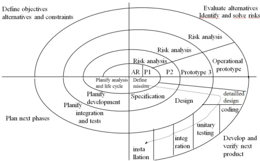
2.2.4. Spiral model (Boehm, 1986)
The spiral model [13] is a model based on the iteration of four steps (Figure 2-5). While these steps will be the same, the content they are producing is evolving through the iterations. Thus, this model is based on the following steps:
- Definition of the goals, possible alternatives and constraints of the project
- Evaluation of the alternatives based on the requirements and the constraints of the project. This step is including a prototyping activity which will feature a prototype more and more operational through the iterations
- Design of the more suitable solution from the previous step. This step is including the design and the verification tasks described in the V-model.
- Planning of the next step by affecting tasks to perform to the design team members
Figure 2-5 Spiral model development process (Boehm, 1986)
This development cycle can be used to explore alternative design. The iterations allow to refine the requirements, the needs and the specification of the application. Once the refinement is sufficiently mature for a decision making, the design team is proceeding to a development cycle such as the waterfall model or the V-model. While this development cycle is expensive and lengthy, the advantage of this development cycle is that it takes into account the usability of the final application.
2.2.5. Rational Unified Process (Kruchten, 2004)
The Rational Unified Process (RUP) [14] is a development process aimed at the creation of a product matching the users’ needs. This design process is:
- Iterative and incremental: the project is divided into short-term iterations which produce an executable version of the application. This version is incremented during each iteration - Model based: the architecture of the application must be graphically modeled. This process is
12
Figure 2-6 RUP development process
The Figure 2-6 is representing an overview of the process which is composed of two dimensions: - The horizontal axis is corresponding to the time and the deployment lifecycle which include
the inception, the elaboration, the construction and the transition
- The vertical axis is representing the discipline, the people and artefact involved in the design process. This include the business modeling, the requirements, the analysis and the design, the implementation, the tests, the deployment, the change management, the project management, and the environment
RUP is a turnkey approach proposed by IBM who provide the process and the tools. The tools offer a canvas of projects, a sharing of documents within the design team and promote the reuse of models. However, this approach is linked to Rational tools and while this approach is compatible with the production of usable systems, the required tools are expensive.
2.2.6. AGILES methods (Cockburn, 2002)
The AGILE methods (officialized in 2001 by the Agile manifesto [16]) are aimed toward the satisfaction of the client by integrating him within the design process. These methods are based on four fundamental values:
- The team (“Individuals and interactions over processes and tools”)
- The application (“Working software over comprehensive documentation”) - The collaboration (“Customer collaboration over contract negotiation”) - The acceptation of changes (“Responding to change over following a plan”)
The SCRUM approaches (for the management of the development) and eXtreme Programming (for the software development) are following these precepts.
SCRUM (Shwaber, 2002)
SCRUM [17] is an approach for the management and the tracking of the software development. It is an iterative and incremental approach. A customer representative is called “product owner” is responsible to transmit the orientation of the project to the design team, to define the features to develop and suggest an order of implementation to provide a tool matching his needs. The product owner is entering this information in the product backlog which list the needs and the features desired by the customer. This list is ordered by the value granted by the product owner which is defined by the following criteria: the return on investment, the criticality of the feature for the system or the users, the development cost, etc. The product backlog is visible for the whole team and is used for a better
13
communication on the goals of the project since each team member can see the features asked by the product owner.
Figure 2-7 The steps of the software development with SCRUM retrieved from https://www.neonrain.com/agile-scrum-web-development/
The development is decomposed into iterations called “sprints” which last from three to four weeks. This short duration allows to quickly deliver releases of the software to the product owner which includes the features listed in the product backlog. Another advantage of this short duration of iterations is that it allows the product owner to adjust the features he ask as the project is progressing. This approach is strongly focused on the customer’s needs but in the case where the customer is not the final user. The usability of the interactive system can be taken into account through the use of user stories. These user stories can be written to accurately describe the use of the system by an end-user and can be written by anyone, including an end-user.
eXtreme Programming (XP, Beck, 1999)
The eXtreme Programming [18] (Figure 2-8) is defining a set of methods for guiding the production of a software. In XP, User stories are similar to use cases defined in UML and replace the specifications given by the customer. These user stories are written in natural language by stakeholders and are used by the designers for evaluating the duration of the iteration and for testing the design.
14
Figure 2-8 eXtreme Programming development process
An iteration starts with the release planning of the iteration, the scenarios and the tests to implement. The planning is done by the designers and the customers. The customers choose the scenarios to implement in the next iteration while the designers evaluate the duration of the iteration. The spike solution is done by exploring several solutions and are planned only for difficult problems to solve. A planning is imposed for each scenario: a scenario must be implemented within one to three weeks, otherwise, the scenario must be decomposed. A test is representing a specific behavior expected by the system. A user story is validated once each unit test associated to this scenario is valid. When tests are successfully performed, the current version of the application is updated with the last features (small releases).
XP also defines rules and methods for the process (planning, coding, design and test). The advantage of this method is that it is easy to apply, it is cost-effective and features numerous iterations and releases of versions. The time is essentially spent on the technical aspects: development and tests. However, this method does not cover the steps before and after the development such as the analysis of the users’ needs and the maintenance of the application.
Overall, AGILE methods are interesting for ensuring the customer satisfaction by controlling the costs and the time dedicated to the development thanks to the iterative and incremental approach. However, these methods do not guarantee the reliability and the usability of the released product.
2.2.7. Star model (Hartson, 1989)
The star model [19] in the Figure 2-9 is featuring six different steps of the development process. The main principle of this model is that any step of this process must be evaluated before proceeding to the other steps. Thus, this process can start at any of the five steps located at the end of each branch of the star but the evaluation is always done after each steps of the process. This model is flexible and does not impose any path for the process.
15
2.2.8. The layered development process model (Curtis, 1994)
The layered process model (Figure 2-10) has been proposed by Curtis and Hefley in [20]. The main principle of this model is to separate the development into two steps: the “Software Engineering” corresponding to the standard software development and the “User Interface Engineering” focusing on the Human-computer interaction.
Figure 2-10 The layered process model [20]
This process is establishing a relationship for each steps of the development between the software engineering (e.g. system testing) and the user interface engineering (e.g. contextual observation). This process is defining a clear separation between these two parts of the interactive system.
2.2.9. The Object-Oriented User Interface (OOUI) design process (Collins, 1995)
The OOUI design process [21] represented in the Figure 2-11 is an iterative process. It is focused on the task analysis by considering it as a key step of the UCD process. Thus, human factors and software engineering factors are integrated within this process. This design process is more focused on describing the relationship between these factors rather than providing a method for developing an interactive system.
Figure 2-11 OOUI design process
2.2.10. The Iterative-cyclic process (Rauterberg, 1992)
The iterative-cyclic process [22] is a user-centered participative process and is composed of four quadrants (Figure 2-12):
16
- Bottom-left quadrant: Specification. Creation of the user-interface as well as its conceptual and organizational description
- Bottom-right quadrant: Implementation. The application is created
- Upper-right quadrant: Trial and Assessment. The application is tested and validated to check if it is compliant with the users’ requirements.
Figure 2-12 The iterative-cyclic process
The iterative-cyclic process is completing the standard design process with the following concepts: - Final users’ requirements during the needs analysis step
- The use of prototypes during the specification step - A formal specification step during the specification - Usability tests during the validation
This design process allows the development of usable interactive system.
2.2.11. User-centered System Design (Gulliksen, 2003)
The User-centered System Design (USCD) [23] is a process dedicated to support the usability of the system during the design process as well as during the lifecycle of the system.
17
Figure 2-13 Usability Design Process
This process emphasizes the following concepts: - The user-oriented aspect
- The active engagement of the user from the beginning of the process - The iterative and incremental development
- The simple representation of the development understandable by users and other stakeholders
- Usage of prototypes
- Usability goals for leading the development - Explicit and clear development activity
- Pluridisciplinary team including usability expert during the process
- A holistic development by developing in parallel the aspects that will influence the future usages
- The customization of the process depending on the organization
The goal of this process is to balance the interaction design, the analysis and the evaluation. Thus, this process can be divided into three steps (Figure 2-13): Requirements analysis, growing software with iterative design and deployment. This process is imposing the release of a Usability Design Guide which must feature information from the requirements analysis as well as the different design choices made during the process.
During the requirements analysis, the design team is focused on the understanding of the goals of the company, the final users’ tasks and needs and on establishing usability and development goals. This part of the design process is continually evolving during the development process while the required information can be added.
The second step contains three main loops: the conceptual design, the interaction design and the detailed design. These iterative loops include the design and the evaluation.
18
The deployment step contains the different guides to help using the system such as user guide, online help and training. This step is not necessarily final and can be the end of an iteration cycle. The deployment can be used to present the different subparts of the system and allow to adjust either the system or the process.
While this design process is oriented toward the usability of the system, it does not feature all of the design steps. Thus, it must be integrated within a more complete process.
2.2.12. The Usage-Centered Design (Constantine & Lockwood, 2002)
The Usage-Centered Design process [24] is a design process focusing on the tasks to support as opposed to other user-centered design processes which focuses on the user experience and his satisfaction.
The Figure 2-14 below extracted from [24] is comparing the User-centered and the usage-centered design processes.
Figure 2-14 Comparison table between the User-centered design and the Usage-centered design (retrieved from [24])
One of the key aspect of the usage-centered design process is that it is based on models: - The “Role model” captures the characteristics of roles that users plays
- The “Task model” defines the structure of the work the user needs to accomplish
- The “content model” or “abstract prototype” describes the content of the UI and its organization
This design process starts with two preliminary steps:
- The “Essential purpose and preconception” which clarify business and define user purposes - The “Exploratory modeling” in which the design team identify questions and uncertainty in
user requirements by sketching draft of models
After these preliminary steps, the process is followed by iterations of the design of the different models which are roughly designed at first. The iterations include the design of the overall architecture of the UI (organization, navigation, look and feel, tasks to be covered), the modelling of the user role through card based modelling and the inspection of the models produced.
19
2.2.13. The ISO User-Centered Design (UCD) process
According to the ISO standard 9241-210 revised in 2018 by [25], the User-Centered Design (UCD) is an iterative design process in which the end-users and their needs are the main focus. This design process, as illustrated below in the Figure 2-15, is based on the study of the context of use of a software, the specification of the application, the production of a design solution and the evaluation of this solution until the solution designed is meeting users’ goals and needs.
Figure 2-15 ISO 9241-210 standard for human-centred design processes for interactive systems
In the early iterations of the design process, the perimeter of the design solution is blurry and the specification has to be refined through the study of the context, the collection of data, the study of results from previous iterations, multiple tries on the design solution and validation with end-users. The production of a design solution can either be a step in which the design team explores a new alternative of design or refine a solution and specify the final design adopted. On top of that, new needs can appear during the iterations. Those conditions imply that the first iterations and thus each step should be limited in terms of investment to get early feedback on what is wrong on the design choices or the understanding of the users’ need. This approach will minimize the cost of maintenance and the development cost of unwanted features and ill-suited user interfaces and can be supported by using sketches and paper prototypes.
Indeed, the prototyping activity allows the stakeholders of the design process to collaborate to produce a partial representation of the interactive system. There are several advantages to use prototypes: it is a solution that is inexpensive to produce quickly and it allows to communicate over ideas by featuring a concrete representation of a solution.
In addition to prototypes as a communication medium, stakeholders of the design process also use annotations during the prototyping activity for various purposes such as adding complementary information on prototypes, listing concepts and ideas, noting relevant information, or reminders for future activities.
Later on, the iterations of the design process might require more accurate prototypes in terms of interaction or graphical representation which implies a change in the tools used for the creation of prototypes.
20
Thus, the needs of the design team regarding the creation of prototypes evolves during the design process and are depending on the goal of the prototype set by the design team.
2.2.13.1 Presentation of the tasks of the UCD
For the sake of simplicity in the presentation of the UCD, the activities “understanding of the context” and “specification of the users’ requirements” will be studied together as one task.
Thus, the UCD process can be broken down into the iterations of 3 main tasks: collecting and refining information from users, the production of a solution from the information collected that might meet user requirements and needs, and the evaluation of the solution by presenting it to users. However, the UCD does not show how to perform the tasks.
Collecting and refining information
This task consists in collecting the information relevant for the interactive system being designed and refining the information in order to make it usable for the following tasks of the design process. This can be done through various activities (e.g. identification of users, analysis of the context, interviews with end-users, creation of personas, modeling of the users’ activities).
The goal of the integration of those activities in the studies is to have a better understanding of the context in which artefacts are produced and used during the design process as well as to identify a potential track for building a knowledge base of the design process using those artefacts. This knowledge base will then be used for the traceability of the decision made throughout the design process.
On top of the study of those activities, the evolutions of artefacts and resources used and produced during the UCD process will be examined. In each of the tasks of the design process, a set of artefacts are produced or used as a reference throughout the different iterations. Those artefacts can be of various nature like guidelines provided by the customer, the transcription of user interview, user test results, or prototypes of the solution. They contain valuable information about the context of the project but also about the progress of the design process.
Production of a solution
This task consists in modeling the different aspect of the interactive system by following the information specified during the previous task. This modeling can be made by creating prototypes that will specify and respect the specification of the design of the interactive system. The creation of prototypes can be divided into several tasks to cover the different aspects of the interactive design: designing the UI, the behavior of the prototype, the data manipulated by the interactive system, the services communicating with the interactive system and so on.
The goal of the integration of this activity is to have the mean to study and identify the different goals of a prototype, what are the key elements of those prototype depending on the goal, evaluate the suitability of prototyping tools regarding those key elements, study the process of creation of a prototype and of the resources used for this creation as well as study the usage and the evolution of the prototypes produced.
Another aspect to examine is the exploratory approach enabled by the usage of prototypes while keeping in mind the traceability of design choices and evolutions through the design process. The design process can lead to different prototypes that can be developed in parallel given a limited set of resources. In the prototyping context, each potential solution aims to solve the same problem and they can be tested. Indeed, prototypes can be inexpensive to produce thus allowing a comparative study
21
between concurrent prototypes. Furthermore, thanks to user tests and their results, it is possible to provide concrete arguments to which ideas from prototypes the design team should promote during the decision process.
Evaluation of the solution
This task consists in the evaluation with end-users of the solution produced during the previous step of the design process. The results of the evaluation will allow the design team to gather information on the adequacy of the design solution with the users’ needs and requirements as well as to refine the existing needs and to inquire about eventual new needs and requirements.
The goal of integrating this activity in the study is to pursuit investigations on the integration of the feedbacks within the design process and its impact on prototypes, the processing and evaluation of those feedback for the traceability of the design and for the management of the information by the design team.
2.3. Synthetic analysis of the development processes
The Table 2-1 below present a synthetic analysis of the different development process listed in the previous section. In that table, development processes are classified according to actors involved in the process, the involvement of the client with the project type of process (iterative or sequential) and the list of artifacts produced. This classification is based to the original description in the literature. However, we should assume that in real life projects these macro projects are not always instantiated as such and might be adapted to cope with the idiosyncrasies of specific projects.
Actors of the process Active involvement of the client Active involvement of the end-users Type of
process Artefacts produced Waterfall
process Development team No No Sequential
Requirements, Specifications, Code, Tests, Executable
V-Model Development team No No Sequential Specification, Architecture design, Code, Tests, Executable
Nabla model Development
team, end-users No
Yes (for the
evaluation) Sequential
Real model, Reference model, Evaluation results, Validation
results, Code, Tests
Spiral model Development team, Customer, Stakeholders, users, maintenance organization Stakeholders for reviewing purpose Optional for
reviewing purpose Iterative
Requirements, Specification, Alternative designs, Constraints, Risk analysis,
Prototypes, Executable
Rational Unified Process
Development team, Tester team,
Managers, Additional Workers, Customer
Yes for agreeing the description of the
requirements
At the end of the process (“Product Release Milestone”) during the “transition phase” Iterative
Business case, Use Case model, Project plan, Risk assessment,
Project description, Prototypes, Requirements, Specifications, Architecture description, Development plan,
code, tests, Executable
Scrum Scrum master, Development team, Product Owner Yes as a Product Owner for prioritize requirements, tasks, and features through the Product Backlog
Only when the client is an user or when end-users participates to the creation of
User Stories
Iterative
User stories, Product Backlog, Sprint Backlog, Increments,
Releases
eXtreme Programming
Development team, Customer
Yes for planning and reviewing
Only when the client is an user or when end-users participates to the creation of
User Stories
Iterative Plans, User Stories, Releases, Tests, Code
Star model Development
team, End-Users No
Yes for the
evaluation Iterative
Requirements, Specifications, Human-Computer Interface
models, Prototypes, Implementation
22
Layered development process model
Development
team, End-users No Yes Iterative
Requirements, Users’ task and analysis, Design, Implementation, Tests The Object-Oriented User Interface Development team, End-users No
Yes for evaluating
the prototypes Iterative
Requirements, Users’ task and analysis, Design, User’s conceptual model, Prototypes,
Implementation
Iterative cyclic process
Development
team, End-users No Yes Iterative
End-user requirements, Users’ tasks analysis, Formal specifications, Design specifications Prototypes, Releases, Statistic, Interview,
Assessment results, Tests
User-Centered System Design
Development
team, End-users No
Yes from the beginning to the
end
Iterative
Usability Design Guide, Models, Scenarios, Conceptual design, prototypes, Evaluation
results Usage-Centered design Manager, end-users, application domain experts, developers, and other stakeholders
Not mandatory Yes Iterative
Role models, Task models, Task cases, Content models, Visual
and interaction design
ISO User-Centered
Design
Development
team, End-users No
Yes from the beginning to the end Iterative End-Users’ Requirements, Specification, Prototypes, Implementation, Evaluation results
Table 2-1 Synthetic analysis of the development process
As we shall see, all the development processes analyzed in this chapter acknowledge that many actors participate in the development process. Even when specific roles are not properly labelled, actors are considered part of a development team. This aspect justifies that communication between actors must occur somehow. In our classification, we consider the involvement of clients (people who order the development of the project and/or have knowledge about the inner business model but do not necessarily will use the software produced) and end-users (people who will interact with the resulting software). Whilst both client and end-users are sources of requirements for applications, many development processes such as the Waterfall process and V-Model do not mention the presence of these actors.
Most of development processes propose some level of iteration among the steps. Indeed, the various actors needs to collaborate toward a common goal through the different iterations. This specificity of the design process imply that the design must be understandable by each stakeholders of the design process and that the results of the evaluation done at the end of each iteration must be followed up by tasks compliant with the conclusions of these results.
This review of design process showed that various artefacts are produced and reused at different phases of the process by many actors of the design process for various purposes (e.g. planning an iteration, reviewing the design, establish a common understanding of the project). These artefacts support the activities of the design process and evolve depending on the results of evaluations and validations. Nonetheless, there is not a standard set of artifacts to be produced
2.4. Conclusion
In this chapter, we have presented a review of macro development processes for interactive systems which has been previously published in the PhD thesis of Célia Martinie [9]. In this review, we briefly presented the sequence of activities of the different design process and given an analysis of these design process. This analysis lists various properties of the design processes and especially the different actors involved and some of the artefacts produced during the activities of the process.
23
In [26], I. Khaddam, H. Barakat and J. Vanderdonckt explain through the method engineering that there is a dependency to the tools used to perform the different tasks of a design process. However, as explained in the Chapter 4, tools support of annotation is not suited for its use in the context of the design process. Indeed, annotation support is not homogenous since each tools propose their own implementation of annotations, thus making it difficult to process annotations on a global level. Whilst annotations are often used to support the activities related to the evolution of artefacts, we did not have found in the literature any design process that make explicit reference to annotations. The practice shows that annotations are widely adopted as a tool for the design of artefacts, but their integration within the design process is still overlooked. This absence of articulation between annotations and macro development processes for interactive system motivates the development of micro processes, described in the Chapter 5, for handling annotations.
![Figure 2-14 Comparison table between the User-centered design and the Usage-centered design (retrieved from [24])](https://thumb-eu.123doks.com/thumbv2/123doknet/2225987.15474/31.892.197.699.453.722/figure-comparison-centered-design-usage-centered-design-retrieved.webp)

![Table 3-2 Observations and conclusions on the information necessary for the rationale design in [60]](https://thumb-eu.123doks.com/thumbv2/123doknet/2225987.15474/45.892.109.788.893.1091/table-observations-conclusions-information-necessary-rationale-design.webp)