HAL Id: hal-02191807
https://hal-lara.archives-ouvertes.fr/hal-02191807
Submitted on 23 Jul 2019
HAL is a multi-disciplinary open access
archive for the deposit and dissemination of
sci-entific research documents, whether they are
pub-lished or not. The documents may come from
teaching and research institutions in France or
abroad, or from public or private research centers.
L’archive ouverte pluridisciplinaire HAL, est
destinée au dépôt et à la diffusion de documents
scientifiques de niveau recherche, publiés ou non,
émanant des établissements d’enseignement et de
recherche français ou étrangers, des laboratoires
publics ou privés.
A method of measuring the total D.C. electric field in
the vicinity of a spacecraft using artificially injected
charged particles
Michel Pirre, Michel Hamelin, T.R. Sanderson, G.L. Webb
To cite this version:
Michel Pirre, Michel Hamelin, T.R. Sanderson, G.L. Webb. A method of measuring the total D.C.
electric field in the vicinity of a spacecraft using artificially injected charged particles. [Rapport de
recherche] Centre de recherches en physique de l’environnement terrestre et planétaire (CRPE). 1979,
41 p., figures, graphiques. �hal-02191807�
CENTRE NATIONAL D'ETUDES DES TELECOMMUN 1 CAT 1 ONS
CENTRE NAT I ONAL DE LA RECHERCHE SC I ENT I F I (
CENTRE DE RECHERCHE EN PHYSIQUE DE L'ENV I RONNEMENT TERRESTRE ET PLANETA I RE
NOTE TECHN I QUE CRPE/68
A METHOD OF MEASURING THE TOTAL D.C. ELECTRIC FIELD I N THE V I C I N I TY OF A SPACECRAFT USING
ARTIFICIALLY INJECTED CHARGED PARTICLES
by ,
M. PIRRE and M. HAMELIN and
T.R. SANDERSON and G.L. WEBB (ES TEC)
C.R.P.E./P.C.E.
45045 - ORLEANS Cédex
Le Chef du Département PCE
Lé Oirécteur
"
C. BEGHIN
.
�J.hUËBLOT
I N THE V I C I N I TY OF A SPACECRAFT
USING
ART I F I C I ALLY I NJECTED
CHARGED
PART I CLES
by
M. PIRRE
UNIVERSITE D'ORLEANS AND CNRS/CNET/CENTRE DE RECHERCHE EN PHYSIQUE DE L'ENVIRONNEMENT TERRESTRE ET PLANETAIRE - 45045 - ORLEANS CEDEX (FRANCE)
M. HAMEL I N
CNRS/CNET/CENTRE DE RECHERCHE EN PHYSIQUE DE L'ENVIRONNEMENT TERRESTRE ET PLANETAIRE T.R. SANDERSON and G.L. WEBB
ESAÍEUROPEAN SPACE RESEARCH AND TECHNOLOGY CENTRE, NOORDWIJK (THE NETHERLANDS)
ABSTRACT :
A method of measuring both the perpendicular and parallel D.C. electric field in the vicinity of a spacecraft using artificially injected . charged particles is presented. This method uses a rendezvous between the
spacecraft and injected particles after a number of complete gyrations around the magnetic field plus one partial gyration, to measure the field and potential structure at short distances (up to few kilometers or tenth of kilometers) from the spacecraft. The solutions of the rendezvous problem are derived in the general case, and in realistic cases related to possible potential structure due for example to anomalous resistivity and electrostatic shocks. The charac- teristics of the measurements are
evaiuated,in particular the echo delay time of the particles (and hence the time resolution) and the sensitivity (i.e. the minimum electric field, the extent and the magnitude of the potential measurable). Among other, the minimum parallel electric field ( v 1 mV/m) and the minimum time resolution ( v 20 ms) are found to the very suitable to describe potential structures associated with anomalous resistivity and electrostatic shocks. Finally the requirements for guns and detectors are eval uated i.e. their orien- tations, the beam intensity and the detectors time resolution and sensitivity.
- 3 -
RESUME :
On présente
une méthode de mesure des composantes perpen-
diculaire
et parallèle
du champ électrique
continu au voisinage d'un engin
spatial,
utilisant
des particules
chargées
injectées
artificiellement.
La méthode
utilise le rendez-vous
entre un engin spatial et des particules
injectées
effec-
tuant un nombre entier de rotations
autour du champ magnétique plus une rotation
partielle,
pour mesurer
le champ et la structure
du potentiel à de faibles
distances
(jusqu'à quelques kilomètres
ou des dizaines de kilomètres)
de
l'engin spatial.
Les solutions du problème de rendez-vous
sont obtenues dans
le cas général puis dans des cas pratiques
associés
à des structures
du potentiel
possibles
dues par exemple à la résistivité
anormale ou à des chocs électro-
statiques.
Les caractéristiques
de la mesure sont évaluées
et en particulier
le temps d'aller et retour des particules
(par conséquent
la résolution
temporelle)
et la sensibilité
(c'est-à-dire
le champ électrique
minimum, l'étendue et la
valeur du potentiel, mesurables). La
valeur minimum de la composante parallèle
du champ électrique
('" 1 mV/m) et la résolution
temporelle
minimum ( w20 ms)
entre autres sont parfaitement
bien adaptées pour décrire
les structures
du
potentiel associées
avec les phénomènes de résistivité
anormale et de chocs
électrostatiques.
Finalement
les caractéristiques
nécessaires
des canons et
des détecteurs
sont évaluées,
c'est-à-dire
leur orientation,
l'intensité
des
faisceaux,
la résolution
temporelle
et la sensibilité
des détecteurs.
1 - INTRODUCTION
I n recent
years,
much effort
has been devoted
to the
measurement
of the magnetic
field aligned DC electric
fields
proposed
to
explain
results
from early experiments
(HIJLTQVIST
et al.,
1971 ; FAHLESON,
1972 ; MOZER and BRUSTON,
1967 ; REME and BOSQUED,
1971).
Such results
indicating
the presence
of potential
drops
as large as a few KV in the auroral
zone during disturbed
periods
have been followed
by others
identical
results
obtained
from either
direct
measurements
using double probes
(MOZER,
1976 ; MOZER
et al.,
1977) or indirect
methods
using barium
ions as tracers
(HAERENDEL
et al.,
1976 ; WESCOTT
et al . , 1976), anisotropic
distributions
of natural
precipitations
of protons
and electrons
(EVANS,
1975) or "inverted
V"
precipitations
(BURCH et al.,
1976).
At the same time, several
theoretical
explanations
have been
proposed,
for example anomalous
resistivity
(KINDEL
and KENNEL,
1971),
double
layers
(BLOCK and FALTHAMMAR,
1976) or electrostatic
shocks
(SWIFT,
1975) supported
by large drift velocity
driven
instabilities.
As yet, there is no générât
agreement
on these
theories,
nor on the existence
of such electric
fields.
Nevertheless,
it appears
that
there
are two possible
shapes
of the potential
variation
along the magnetic
field lines.
The first
is a small magnetic
field aligned parai lei
electric
field
of large extent,
which could be explained
by anomalous
resistivity.
The second
is a small layer of a few tens of meters
or kilometers
which could be explained
by double
layers
or electrostatic
shocks
associated
with large electric
fields
(of a few hundreds
of mV/m).
Remote sensing
experiments
using charged
particles
have been proposed
by several
groups
as a method which could defi-
nitely
solve the problem.
The basic
principle
of the experiments
is to inject
charged
particles
from a spacecraft
along the magnetic
field lines,
and to
detect
the echoes
obtained
if the beam has been reflected
by the potential
drop
along the magnetic
field line.
The measurement
of the echo delay time as a
function
of the injection
parameters
leads to the knowledge
of the potential
as
a function
of the distance
from the injector.
Such experiments
are able to
describe
in detail
the potential
drop along the field line and so give an under-
standing
of the phenomena
that lead to the existence
of parallel
electric
fields,
or conversely
to disprove
their
existence.
Nevertheless,
such
experiments
have not yet been performed
due to the difficulty
of obtaining
a rendez
vous
between
the echoes
and the spacecraft
when one attempts
to trace
the field
-
6 -
lines over distances
of a few thousands
of kilometers
(WILHELM,
1977).
Indirect
detections
of the echoes
are also possible
using the interaction
of the partioles
with the atmosphere
or a gas release
by detecting
the emitted
light.
In this case,
the injected
intensity
has to be large to obtain echoes
well above the natural
background.
However,
too large an intensity
could
involve
more complicated
interactions
with the medium than the single particle
motion.
But if we limit our ambition
to describe
the electric
potential
over a
few kilometers,
the rendez
vous problem
can be easily solved.
Indeed the
echo delay time can be short enough in order that the spacecraft
does not move
.
over distances
larger
than the gyroradius
of the particles
and so obtain the
rendez
vous on the same spacecraft
which carries
the particle
source.
As we can see above,
much effort
is needed
to find feasible
methods
to measure
the parallel
electric
field by a remote sensing
technique
at
large or small distance.
The aim of this paper is to contribute
to that effort,
studying
the capabilities
of the remote
sensing
experiment
over small distances
to describe
some realistic
structure
of the electric
potential
or at least,
if
that measurement
is not possible,to
measure
the local total electric
field.
This study will be performed
assuming
that only the electric
and magnetic
fields
of natural
origin
act on the trajectories
of the particles.
Other para-
meters
can influence
those trajectories
as for example the potential
difference
between
the spacecraft
and the surrounding
medium,
the interaction
between
the beams of charged
particles
and the plasma or the collision
of the charged
particles
with the neutral atmosphere.
It is not the aim of this paper to discuss
these
e f f ec t s ,
but it is clear
that theoretical
calculations
including
these
and/or
experiments
will be necessary
to prove definitely the
feasibility
of the method.
The two first
effects
are largely
dependent
on the required
intensities
of the
beams which wi II be computed
in this paper.
The importance
of the last effect
decreases
while the altitude
of the measurements
increases.
2 - MEASUREMENTS
REQU 1 RED TO G I VE THE ELECTR I C
POTENT I AL
ALONG THE F I ELD L I NE
2.1 . The echo delay time as a funct i on of i n ject i on parameters Let
Eo be the initial energy of the particles injected at the origin and Y their pitch-angle. The echo delay time t for the particle to go to the
V// : the parallel velocity of the particle
s : the path length along the magnetic f i el d sF : the reflection point
q , m . the charge and mass of the particle B(s) . the magnetic field as a function of s
«'(s) : the electrostatic potential as a function of s
IJ = 0 sin '( : the magnetic moment of the particle which is an B
invariant of motion
Bo : the magnetic field at the injection point
The inversion problem which leads to the knowledge of �' as a function of s knowing t as a function of injection parameters has been solved by WILHELM (1977). In our particular case of short distance measurements the function :
is generally monotically increasing between the injection and the reflection points because the parallel electric field is present close to the spacecraft. This leads to an important simplification of the inversion problem. Furthermore, to simplify the discussion we will consider the magnetic force :
where
�"v',1 : the perpendicular energy at the injection as an equ ival en t electrostatic force associated with a almost constant electric field directed upward for ions and downward for electrons. I ts magnitude depends on the perpendicular energy Wl of the particles and on the altitude of the measu- rements. It is for example
E// = 0.4 mV/m if Wl is 1 Kev at 1000 km and E// = 2.4 mv/m if Wj. is 10 kev at 6000 km.
The echo delay time is thus :
.
where
-
8 -
r
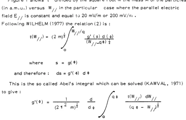
Figure 1 shows t divided by the square root of the mass M of the particles (in a.m.u.) versus
W// in the particular case where the parallel electric field
E// is constant and equal to 20 mV/m or 200 mV/rn . ?
Followinq WILHELM (1977) the relation (2) is : i
where s = 9( ID) 7
and therefore : ds = gl( b) d � (D !
This is the so called Abel's integral which can be solved (KAWVAL, 1971) to give :
and
The knowledge of t as a function of
W�� gives in consequence the value of as a function of s whatever this function is,if the followi ng conditions are fulfilled :
1) the electric field is present close to the spacecraft 2) t versus
W�� is continuously differentiable.
2.2. The echo delay time for both electrons and protons injected upward and downward
Depending on the injection and parallel electric field directions only electrons or ions will be able to be reflected by the potential drop. The use of both electrons and ions injected upward and downward are therefore
desirable to describe the potential above and below the spacecraft. Using relation (1) the echo delay time t isproportional to the square root of the mass of the particles, so that it is advantageous to use the lighest possible ions i .e. the protons to improve the time reso lution of the measurements.
3 - SOLIJTIONS OF TH.E RENDEZ-VOLlS PROBLEM IN THE GENERAL CASE 3.1 . Description of the rendezvous
In this section we will assume that the electric field variations are small 1) spatially over one gyroradius of the particles which will be typically 10 m for electrons and 500 m for protons. 2) temporally as seen from the spacecraft compared with the echo delay time.
Moreover we will neglect the drift of the particles perpendi- cularly to the magnetic field due to gradient or çurvature of the field.
Indeed, the magnitude of such a drift is always smaller than 50 m/s for the energies and altitudes considered in this paper. This value is small in compa- rison with the velocity of the spacecraft and/or the drift due to the perpendi- cular electric fields prevailing in disturbed periods.
The motion of the injected particles as well as the spacecraft can be split into their two components : perpendicular and along B.
Let V be the velocity of the spacecraft with respect to the plasma in the plane P. V is the component of the particle velocity in that plane at injection, a is the angle between the two vectors. We can see from figure 2 that we can obtain a rendez-vous between the projected trajectories of the spacecraft and particles if a and V are chosen correctly. Notice that this is completly di fferent to other methods proposed such as in the GEOS experiment (MELZNER et al., 1978) where a single complete gyration of the particle is required. In our case, a rendezvous is obtained after a number of completegyrationsplus one partial gyration.
Furthermore, if the pitch angle y of the particle at the injection is chosen so that the echo delay time is the same as the time of rendezvous in the plane P, a complete rendezvous is possible. In this case, the pitch angle of the returning particles is y'= 11 - Y .
3.2. Rendez-vous equations - Number of solutions 3. 2 . 1 . Rendez vous i n the pl ane P
From figure 2 it is easy to show that the rendezvous condition in the plane P can be fulfilled if the particle and the spacecraft reach the point R at the same time i.e. if
where
- 10 - t
That 1 eads to : j
where n is the number of gyrations around the magnetic field (on figure 2, ! n = 2), a is between 0 and te. Let V be the vel ocity of the particles in � the spacecraft frame of reference and 8 the angle between
� and Vot
(see figure 3). We can write : f
and
(5) and (6) I ead to
(4) and (5) to
Usina
(6)
Replacing
the value of a in relation
(8) we obtain :
We can note that sin B is essentially positive and in consequence 8 can only vary betv een 0 and 11
the equation
(9)
becomes
If k
is known , the solutions
u of this equation
are obtained
at the
intersection
of the two curves
Figure
4 shows these
two curves
for k = 10. In this case
n
cannot
be
larger
than 2. We notice
that there
are 2 solutions
for each
n (if n
�1 ) and
only one solution
if n is O.
Figure
5 is an illustration of
the rendezvous
in the plane perpendicular
to B. It represents
the computed
trajectories
of the particles
as seen from
the plasma frame of reference
and from the spacecraft
leading
to 3 of the
solutions
shown on figure 4. Using figure 4 we can see that if k is increasing .
z decreases
for a given value of u while
y is constant.
Consequently
the
possible
values
of n increase
as well as the number of solutions.
That means
in particular
that if
Eo
is the same for electrons
and protons,
n is larger
for electrons
than for protons
because
k is larger.
For example if
Vsp
is
7 km/s and if E
is 1 Kev
n is 40 for protons
and 1600 for electrons.
We can note that , using (3) and (5) the times of rendezvous
corres-
.
ponding
to n gyrations
can be written
where
w is the gyrofrequency
n, i
n,1
is one of the two solutions
corresponding
to n gyrations
(i=1 ,2)
3.2.2.
Complote
rer-
��iezvous
(10) can be written as
where
Vu
is the injection
velocity
of the particles.
Figure
6 shows the variation
of tn
for some values
of n as a function
of
Y (solid lines) or
W /,/ (W // = E0sin2Y ) for a given
E
(in this case
Eo
is 1 Kev). The echo delay time is aiso shown in this figure (dotted line)
as a function
of
W,
for some values
of the parallei
component
of the electric
- 12 -
�
A complete
rendezvous
can be obtained
if the echo delay time can
t
,
be made equal to
t n,1
for
a given value of
W//
(orY).
:.
Notice
from figures
6 and 7 that if
Eo
is given (1 Kev in both figures)
the solutions
corresponding
to electrons
and protons
are obtained
for the
same range of parallel
energy
W//.
Nevertheless,
the number
of solutions
is larger
(as 1/ /*m) and the echo delay time is shorter
(as /iT¡) for electrons
z
than for protons.
:
3.2.3.
Conclusion
In conclusion
to this section,
we can say that ,
if we are able to measure
�
the echo delay time
t and
W//
for each solution
of the rendezvous
problem
i'
we can buildthe
curve
t versus
W//
and consequently
derive
the value of the
y
potential
along the magnetic
field as a function
of s as seen in section
2.
�
Ail these
solutions
could be obtained
by injecting
particles
at a given
j
energy
t
in a suitable
range of pitch angle and in the azimuth
range 0 to 11
;
from the
V
direction.
But, that direction
is unknown
!
because
it is a function
of the perpendicular
electric
field.
So let
n be the
angle between
Vox
and the spacecraft
orbital
velocity
Vse
(the direction
of
.
which is known),
if e is the angle between
V
and
VSP and
ni
the angle
-j
between
V
and
V
at the rendezvous ,
we canderive
easily,
using fig. 3,
r
that :
�
n=8+e
E
,
+c
E
and thus
n' - -
n + E ( 1 1)
Because
E can vary between
0 and 2 If
, n and n'
can vary also
j
between
0 and 2 1
. It is therefore
necessary
to inject the particles
in all 1
;
azimuth
around
B and to detect
them also in ail these
azimuths.
;
Finally, we can notice that the measurement of n, n1 and t for s;. given an energy Eo and pitch angle y at the injection leads to a measure of � the velocity vector
Vs , , that is to a measure of the perpendicular component
' of the electric field. Indeed n and rt' give E after relation (11) , that is
I the direction of V . g is also obtained from (11) , then the hnuwledge of
tn�i i \. gives k using relation (10) and therefore the magnitude of V . �
We have seen that the particles must be injected in a suitable range of pitch angle f It is the aim of the next chapter to calculate that range in realistic cases. �
4 - EXAMPLES
OF POSS I BLE
MEASIJREMENTS
OF DC ELECTR I C
POTENT I AL
STRUCTURES
4.1 . Measurement of structures associated_with__small parallel electric fields at low altitude (300 - 1500 km)
As mentioned in the introduction, there are two possible electric potential structures. The first, due to anomalous resistivity, leads to a small parallel electric fields of large extent. Theoretical calculations lead to electric field strengths lower than 3 mV/m at about 1000 km, decreasing with altitude
(SHAWHAN et al., 1978). On the other hand, experimental measurements
(MOZER, 1976) lead to larger electric fields up to 10-20 mV/m below 500 km. In this altitude range (300-1500 km) the measurements can be performed by satellites travelling at about 7 km/s or by high altitude sounding rockets the velocity of which in the plane perpendicular to B is much smaller (", 1 km/s). Figure 8 shows an example of curve t versus
W// which could be obtained at 1000 km by injecting 1 Kev electrons and assuming a perpendicular electric field of 50 mV/m oriented at 45° to the spacecraft velocity. The parallel electric field is assumed to be uniform and ranges between 1 and 20 mV/m. The accuracy of the measurement is mainly a function of the accuracy of measu- rement of the pitch-angle (this angle can be measured at the injection or at the detection because the return particles have a pïtch-angle y' = n - Y ).
We can see that the accuracy needed is certainly too high to measure such electric fields using satellites. Indeed, it is almost impossible to separate particles with 90° pitch angles corresponding to no parallel electric field (if we neglect the magnetic force) from those with pitch angles ranging between 90° and 87°.
On the other hand using sounding rockets,the accuracy could be sufficient to measure electric potential structure associated with parallel electric fields above 5 to 10 mV/m.
We can see also that using 1 Kev particles we can describe the potential structure up to 200 V if
E// is 20 mV/m i.e. up to 10 Km from the space- craft. I
f E// is decreasing up to 5 mV/m that distance decreases to 1 Km (20 V). By using 10 Kev particles we could describe the potential up to 2 kV in the first case and up to 200 V in the second case. The equivalent electric field (due to the convergence of the field lines) is now 4 mV/m and therefore has to be included in the calculations.
- 14 - f \ As we have seen above the proposed method is not sufficiently accurate to '' describe potential structures associated with small parallel electric field � ( � 5 mV/m using rockets and � 20 mV/m using satellites). Nevertheless, if f we assume that the parallel component of the electric field is not varying over | the distance covered by the particles along the field lines (i.e. few km) we '\ will show that the measurement of this component (which we will cail the "local
parallel component") is possible using electrons alone.
4.2. Measurement of the local parallei component using electrons \ In order to understand easily the method let us neglect the non uniformity of i B as a first approximation. If there is no parallel electric field the electrons � injected outside of the plane P perpendicular to B are lost and those injected i perpendicularly will meet the essentially unmoved spacecraft during the first \ gyration, so the echo will be received before one gyroperiod. On the other | hand, if a parallel electric field exists the particles injected outside of P can 1 rendezvous after many gyroperiods as described in the previous sections, j if they drift far enough along B to avoid the satellite after one gyroperiod. ! Therefore, we can conclude that if long echoes (echoes for which the echo [ delay time is many y gyroperiods)exist, it is the signature cf s parallel electric �
field. f
Now, let us include the effect of the convergence of the magnetic field which I; is equivalent to the effect of a small parallel component of the electric field *
, (hence forth called equivalent electric field to distinguish it from the real | electric field). We are going to show as a first step, that if the energy of the
;'. electrons is small, the previous conclusions are yet valid. Indeed, let us assume ( no real parallel electric field in the case of fig. 8 for rocket measurements | (the equivalent electric field in this case is 0.4 mV/m directed downward). �
L,. It is possible to show that electrons with pitch angles varying between 90° } and 89°4 at the injection could lead to long echoes (see fig. 8). But, the calcu- ! lation of the maximum drift along B shows that it is no more that 14 cm after one ! gyroperiod. Thus, for a spacecraft size of typically - 1 m the particles will j. return to the spacecraft after one gyration as previously. For smaller pitch i; angle, it is possible to show that the existence of long echoes is possible if f the real parallel electric field is larger than v 1 mV/m directed downward or i larger than 1 .8 mV/m directed upward (in this case the maximum echo delay % time is 5.6 ms). The existence of long echoes is therefore the signature of a
parallel electric field larger than 1 to 1 .8 mV/m. In a second step, we are going to show but in fact more information can be obtained on the value of the real parallel electric field if we change the energy of the injected electrons.
Indeed, let us increase the energy Eo of these electrons. We have seen that the equivalent electric field is increased. I
f Eo is increased to 4 Kev for example , that field becomes 1 .6 mV/m. Moreover, it is easy to show that the available pitch angle range to obtain a rendezvous is independent of E , 9 therefore, from fig. 8 we can see that if equivalent
E// is now 1 .6 mV/m the available pitch angle range is 90° to 87°65. The maximum drift of the particles after one gyroperiod in these conditions is now 1 .25 m. So, even in the case of no real parallel electric field long echoes are possible. Per contra, we have to note that if the real parallel electric field is close to 1 .6 mV/m and directed upward (i.e. in the opposite direction to the equivalent electric field) the particles will hit the spacecraft after one gyration, so long echoes are impossible. In the particular case considered here, the range of real parallel electric field for which these long echoes are impossible is 0.8 mV/m to 2.4 mV/m. Figure 9 shows the range of parallel electric field for which the long echoes are received (solid lines) or not (dotted lines) if E is 1 Kev and 4 Kev. If we assume that E// is upwards (as found in many experiments), it is shown that :
1 -
E// is between 0 and 0.8 mV/m if long echoes are received for 4 Kev electrons but not for 1 Kev.
2 - E// is between 0.8 and 1 .8 mV/m if no long echoes are detected.
3 - E// is between 1 .8 and 2.4 mV/m if long echoes are received for 1 Kev electron but not for 4 Kev electrons.
4 -
E// is larger than 2.4 mV/m if long echoes are received for both energy. If
E// is assumed to be upward or downward, it can have an uncertainty because it may be also smaller than 1 mV/m downward in the first case and larger than 1 mV/m in the fourth case. I n the two other cases, there are no uncertainties. It is obvious that the measured range of possible values of E// can yet be reduced if the number of energies considered increases.
These results are obtained assuming that the time of rendezvous is maximum. Using (10) that means that e must be close to 90°. For those requirements to be fulfilled, it is necessary to inject the particles in different directions because the perpendicular electric field component is not known. That can be realised using 8 guns, the axis of which being in the plane perpendicular to B at 45° to each other. So, in ail the cases there is one gun for which 1 B - 90° � is s smaller than 22°5 that is close enough to 90° in order that t be larger than
v
-
16 -
i
The natural - 3 or 4° divergence of the beam is then theoretically enough to inject particles to the right pitch angles. The detectorsmust be able to receive the particles in ail the possible directions of the plane perpendicular
to B, and in a small range of pitch angle around 90°. The time resolution of i these detectors must be smal I comparedwith the time of rendezvous . It can i be typically 100 us. The time resolution of the measurement depends on the , echo delay time and on the number of energies considered if a new energy is ; injected only when the echoes corresponding to the previous injection has been : or would have to be received. In the case considered, the echodelay time is : typically 10 ms. The time resolution is therefore 50 ms if we use 5 energies. f Finally, it is interesting to estimate the influence onthe trajectories of the ( elastic collisions between the electrons and theneutral atmosphere which change �
the pitch angle of the electrons. Assuming the total elastic collision cross j section to be typically'5.10- 16 cm2 (BANKS and KOCKARTS, 1973), the distance
t
�
covered by electrons between the injection and the rendezvous to be 100 km � and the number of atoms to be between 106 and 10 per cm3 at 800 km and ? between 10 to 108 per cm3 at 500 km depending on the local time and on the
� �
solar activity (CIRA, 1965), it is easy to show that this influence is small at 800 km J* f
because the number of electrons which collide with an atom over the distance i covered is only 0.5 % to 5 %. But, it can be important at lower altitude, indeed ! this number increases to 5 % to 50 % at 500 km. These collisions will have x therefore to be included into the calculations if the measurements are performed j.
at too low altitude. �
4.3. Measurements of potential structures associated with large electric fields t The second kind of possible structures are the so called double layers (BLOCK j. and FALTHAMMAR, 1976 ; SHAWHAN et al. 1978, GOERTZ and JOYCE, 1975) � or electrostatic shocks (SWIFT, 1976) which lead to large total electric fields � up the few hundreds of mV/m in small region of a few kilometers. These layers f are expected to be obl ique (SW I FT, 1976) and in co nsequence could extend over {
large altitude range. :
Several measurements could be explained by the existence of such structures,
that is "inverted V" precipitations (BURCH et al., 1976) dipole probe measure- ; ments (MOZER et al., 1977) or barium ion jets acceleration (HAERENDEL et
al . , 1976 ; WESCOTT et al . , 1976). These measurements have been performed between 2000 and 8000 km and show potential drops ranging between a few tens of volts and a few kilovolts. Figure 10 shows the possible structure of the equipotentials (SWIFT et al., 1976) which could explained both the "inverted V" precipitation and dipole probe measurements. The inclination of the equipotentials
is arbitrary. But, because the dimensions perpendicular to the magnetic field are of a few kilometers or hundred of kilometers as a maximum and on the other hand can be of a few thousand of kilometers along B , that means that the angle between B and the equipotential is often low . Therefore, the parallel component of the electric field can be assumed lower than the perpen- dicular one. The total field can be very large up to 500 mV/m.
Figure 11 shows an example of curve t versus W// that can be obtained injecting 7 KeV protons at 3000 km assuming a perpendicular electric field of 200 mV/m oriented at 45° to the satellite velocity. The parallel electric field is assumed to be uniform and to range between 20 mV/m and 100 mV/m. The accuracy of the measurement of the pitch angl es could be enough todescribe the potential structures associated with parallel electric field of this magnitude and it is clear the larger the parallel electric field the better is the accuracy of the measurements. We can see that using 7 KeV particles we can describe electric potential up to 2 kV if
E// = 100 mV/m but just up 100 V if E// = 20 mV/m. The total potential attainable can be increases theoretically by increasing the energy of the particles but we will see in the next chapter that especially for ions we are 1 imited by the intensity needed.
Figure 12 shows the same curves assuming a perpendicular field of 500 mV/m. We can see that the accuracy of the measurement of potential structure asso- ciated with the same parallel electric field decreases when the magnitude of the perpendicular one increases. We can conclude roughly that the measurement is possible if
E///Ej)_ is s I arger than about 10 %. If E// is lower we can just measure the local component by the method described before. As we have seen above, the measurement of the perpendicular electric field component is also possible and is very interesting in the case of electrostatic shocks because the time resolution is very good : 4 ms using electrons. Moreover the accuracy of the measurement is increased if the corresponding drift velocity is larger than the spacecraft velocity which is the case in the electrostatic shocks.
The accuracy of the measurement of the perpendicular component using our method is the best if 8 B is close to 90°. As previously shown this can be realised in ail the cases using 8 guns with their axis at 45° to each other in the plane perpendicular to B.
To measure at the same time the perpendicular component of the electric field and the local parallel component (assuming that this one is small) the detectors must have the same characteristics as those already defined but � moreover they must be able to measure the azimuth of the return ing particles.
- 18 - v-
The knowledge of the azimuth at injection is also necessary ; that can be possible if we code the injected pulses. Using as before 5 energies the time resolution of the measurement can be very short (about 20 ms in the case of fig. 12).
I f now
E�� i large we must use both el ectrons and protons and the detectorsmust be able in addition to measure the pitch angle of the returning
particles. The injection must be moreover swept over the total range of I �' pitch angl needed. I n this case at each injection from the guns over the i total pitch angle range it is possible to receive the echoes of 4 of these f guns (because as seen before echoes are possible only for 6 between 0 and n). 'Ir ! That means that we know 4 points on the curve t versus W��. I t seems ; reasonable therefore to inject the particles with two different energies which ' give now 8 points on the curve. The time resolution of that measurement depends
on the complexity of the detectors that is if these are able to measure instanta- .i neously or not the pitch angles. If it is not the case, assuming that the typical f t value of the total pitch angle range is 60° to 120° and that the pitch angle
range resolution must be 1 2° , the time resolution is 250 ms using electrons and 10 s using protons. That resolution is sufficient in the case of electrons, but certainly not in the case of protons. More complex detectors are therefore needed in that latter case.
5 - CALCULAT I ON OF THE RETURN 1 NG FLUES AS A FUNCT I ON OF THE I
I NJECTED I NTENSI TY .,
The feasibility of the method is partly dependent on the intensity of beams � needed for the returning fluxes be detectable. The calculation of these fluxes j is therefore necessary.
Let Oxyz be a spacecraft frame of reference where Oy is along Vu and � Ox along B (fig. 5). Let assume that the particles are injected at time t = 0 �, from 0. At time t thecoordinatesof the particles are given if we assume a cons- {
where w = qB m
These particles cross the plane z = 0 (figure 5) each gyroperiod.
After n completegyrationsthey cross that plane at the point M (x� , y, ) and at the the time t' such as :
Let assume now that the injection angles Y and � 3 change from z to Y + dY Y and from 13 to s + d 6 then r = OM move to r + dr where
drY and dr� are the vectors corresponding to a change of Y and 8 respective) y.
So, let J d Q be the number of particles injected per second into the solid
angle d Q = sin y dy d8 . These particles will cross the z = 0 plane after n gyrations at the point M through the elementary surface dS(t') given by :
If N(t') is the number of particles per second and per cl 2, received at M we can write :
At the rendezvous point, this relation is :
- 20 -
Thecomponentsof dr Y and der g can be easily found to be
where
Using
(13):
Therefore
Using (10) and
(12)
we can write
the value of N at the rendezvous
point as :
Let N' be the number of particles
crossing
the unit surface
perpendicular
to the direction
of the particles
at the rendezvous
point,
per second.
The mini-
mum value of N' as a function
of Y and 8 i
easily
found to be :
So N' .
decreases
if E
is increasing
or if B is decreasing
i.e.
if
)
the altitude
is
increasing.
j
As seen before
the time resolution
of the detectors
must be chosen
to be small 1
�'
with respect
to the delay
time which is typically -
150 ms using protons
and
;
- 4 ms using electrons,
so it seems
reasonable
to chose
a time resolution
of
'
5 ms for protons
and 100 us for electrons.
�
To be detectable
the returning
fluxes
must fulfilled
two conditions :
�
(1) The count rate corresponding
to the time resolution
must be large
enough to be statistically
detected.
(2) The fluxes
must be larger
or at least of the same order
than the
natural
ones.
Table
1 gives the minimum count rate in the cases of fig. 8 (rocket),
fig.
11 and fig. 12 , assuming
a typical aperture
oS of the detectors
as = 0.05 cm2 ,
a beam intensity
of 1 mA and a beam divergence
of 1
3°
for electron
beams and - 7°5
for proton beams.
The count rates
are those
measured
by detectors
of an infinitely
small field of view which could
receive
returning
particles
after
n gyrations.
But in the case of electrons
the
returning
angles
of the particles
after
a number
ofgyrationsclose
to n are
also close
to those of these
particles.
Moreover,
the echo delay
times
are
also very similar
(one solution
each -.
1 us). Thus,
finite field of view detectors
will measure
many solutions
in the time resolution
interval
and so the count
rate is often larger,
depending
on the acceptance
angle of the detectors.
The real count rates
can be typically
evaluated
to be 10 times larger.
That is not
the case
for protons.
On the other
hand the count rate due to natural
background
wi I I depend on
the field of view of the detectors
and on their
energy
resolution.
Because
in the
case of artificially
injected
particles
the energy is very well defined it is our
interest
to limit the energy resolution
to a small value.
So, assuming
an energy
resolution
of ÓE =
100 eV, a field of view
an= 2.10-2
ster.
and maximum fluxes
of 10 7 proton/cm 2
.s.ster.Kev
and 10 9 electrons/cm 2
.s.ster.Kev.
we can
compute
a natural
background
of 5 protons
per 5 ms and 10 electrons
per 100us.
We can therefore
conclude
that the typical values of the beam intensities
must be
100 VA to 1 mA for proton and 10 mA to 100 ¡J,A for electrons.
'
We can note that these
intensities
are certainly
too small to lead to large
potential
difference
between
the spacecraft
and the surrounding
medium due to the
non-neutralization
of the spacecraft.
Therefore
only the potential
difference
of the sheath
will act on the trajectories
of the particles
in addition
to the
natural
electric
and magnetic
fields.
Because
this potential
is sufficiently
small compared
with the particles
energy
and
also because
the main part of
the trajectories
is located
far away from the spacecraft
(up to 1 to 10 km along
the magnetic
field lines)
it is certainly
reasonable
to neglect
the perturbations
from the spacecraft
-
22 -
6 - CONCLUS I ON
The solution
of the rendez
vous problem
for charged
particles
injected
and received
by the same spacecraft
after
they have performed
a large
number of gyrations
around
the magnetic
field has been found in the general
case.
If the spacecraft
travels
through
regions
where
DC electric
field exist
it has been shown that the perpendicular
component
can be deduced
from the delay
1
time
of the rendezvous
and the returning
particle
directions
in the plane
;
perpendicular
to B. I t has
also been shown that the measurements
of the electric
(''
j.
potential
along the magnetic
field line can theoretically
be obtained
from the
curve
giving the echo delay time as a function
of the pitch angle of the injected
and returning
particles.
This
curve
can be deduced
from the measurement
of
a large number of solutions
of the rendezvous
problem.
Nevertheless,
consi-
dering
realistic
structures
of the electric
potential
it has been shown that the
latter
measurement
is just possible
in some cases
and in particular
in the so
called
electrostatic
shocks
structure
if the parallel
component
of the electric
field is large enough relative
to the perpendicular
one (larger
than about 10 %).
If this condition
is not fulfilled
only the local parallel
component
c.an be deduced.
In this case the proposed
method is nevertheless
of great interest
to measure
,
ej ther
the possible
DC paral lel
electric
field due to the anomalous
resistivity
�
because
the sensitivity
is low ( v 1 mv/m) or both the parallel
and perpendicular
,
components
in electrostatic
shocks
when the equipotentials
are almost aligned
with the magnetic
field,
because
the time resolution
is very good (of the order
of 20 ms i.e.
about 130 m of spatial
resolution
at 3000 km).
The required
particle
detectors
must be capable
of detecting
the returning
particles
in ail the azimuth
directions
in the plane perpendicular
to B but only in a small range of pitch angles around 90° if we want to measure
the local parallel
component
of the DC electric
field.
They must be capable
of
measuring
the azimuth
of the particles
if we want to measure
in addition
the
!
perpendicular
component
of that field.
In these
two cases
we can use only the
electrons.
The beam intensities
needed
are typically
10 to 100 mA. On the other
hand if the equipotentials
of the electrostatic
shocks
are less
aligned
with the
�
magnetic
field lines,
that is if the parallel
component
is not too small relative
f
?,,
to the perpendicular
one, both electrons
and protons
must be used in order
to
measure
the electric
potential
as a function
of the distance
from the spacecraft,
above and below that spacecraft.
In that case the time resolution
is increased
to
about 250 ms and the detectors
become more complex because
they must be able e
also to measure
the pitch-angle
of the returning
particles.
I has been shown also
that for both the complexity
of the detectors
and the beam intensities
needed
the
use of electrons
is much easier
than the protons-
ACKNOWLEGMENTS
We are very grateful to J.J. BERTHEL I ER and C. BEGH I N for valuable discussions and comments concerning this paper.
- 25 -
- LIGURE
CAPT I ONS -
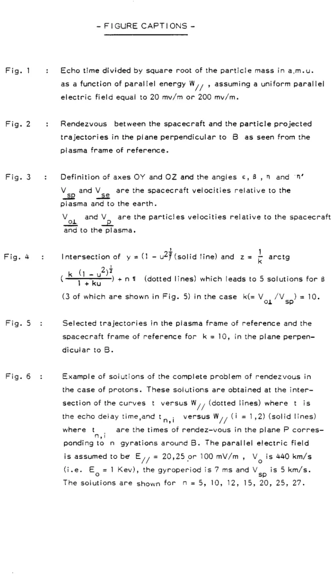
Fig. 1 : Echo time divided by square root of the particle mass in a,m.u. as a function of parallel energy
W// , assuming a uniform parallel electric field equal to 20 mv/m or 200 mv/m.
Fig. 2 : Rendezvous between the spacecraft and the particle projected trajectories in the plane perpendicular to B as seen from the plasma frame of reference.
Fig. 3 : Definition of axes OY and OZ and the angles E, 8 n and '1)'
Z and
V se are the spacecraft velocities relative to the plasma and to the earth.
V ol. and � are the particles velocities relative to the spacecraft and to the plasma.
Fig. 4 : Intersection of y = (1 - urj (solid line) and z
= k arctg
( k 11+ ku ) ) + n tr (dotted lines) which leads to 5 solutions for 8 (3 of which are shown in Fig. 5) in the case k(= V /Vsp) = 10.
Fig. 5 : Selected trajectories in the plasma frame of reference and the spacecraft frame of reference for k = 10, in the plane perpen- dicular to B.
Fig. 6 . Example of solutions of the complete problem of rendezvous in the case of protons. These solutions are obtained at the inter- section of the curves t versus
W// (dotted lines) where t is the echo delay time,and
t n i versus W// (i = 1 ,2) (solid lines) where t are the times of rendez-vous in the plane P corres- ponding to n gyrations around B. The parallel electric field is assumed to be'
E// = 20,25 or 100 mV/m , V is 440 km/s (i.e.
Eo = 1 Kev), the gyroperiod is 7 ms and Vsp is 5 km/s. The solutions are shown for n = 5, 10, 12, 15, 20, 25, 27.
Fig. 7 : As fig. 6 for electrons in the same conditions (Eo = 1 Kev).
Fig. 8 : Solutions of the rendez vous problem showing t versus the pitch-angle Y (or
W//) for 1 keV electrons injected from a space- craft or rocket at 1000 Km, assuming a perpendicular electric field of 50 mv/m oriented at e = 45° to the spacecraft velocity
relative to the Earth. The parallel electric field is assumed to be uniform, and ranges from 1 to 20 mv/m. There are two solutions per gyroperiod (0.71 ps) aligned along the curve. All these solu- tions are therefore indistinguishable from each other.
Fig. 9 : Ranges of parallel electric field for which long echoes are received (solid lines) or not (dotted lines) if E is 1 Kev and
o 4 Kev. The numbers are referred to in the text.
Fiv. 10 Possible structures of the equipotentials after SWIFT et al. (1976).
Fig. 11 : Solutions of the rendezvous problem showing t versus Y