I. INTRODUCTION
Existing holographic techniques (holography, speckle interferometry) [1] enable the measurement of surface displacements or material strains that are due to mechanical, thermal or vibration stresses. The measurement range is mainly determined by the wavelength of the laser used by such techniques; e.g. typically 500-600 nm for visible lasers. Therefore typical displacement dynamic range capabilities are between 10 nanometers to 20 micrometers. Visible laser based holographic interferomety is well established at CSL and has been used in previous projects for the characterization of submillimetric reflectors [2], or thermo-mechanical behaviour of space structures [3]. Expertise gained from these and other applications in (ESA) space projects has led to the following conclusions. First, ESA often demands the (non-contact) measurement of structural deformations or displacements during thermal vacuum cycling over large temperature ranges. In many cases the displacements are too large to be measured by coherent optical techniques employing visible wavelength sources. Second, due to their inherent sensitivity (visible wavelength) optical techniques require opto-mecahnical stabilities, which are typically fractions of a wavelength. They are then also very sensitive to environmental perturbations and require specially adapted operational environments. Based on this a GSTP activity was launched with the aim of developing a technique based on digital holography at 10.6 µm wavelength (LWIR range), associating CO2
lasers with thermal infrared imagers.
This paper presents preliminary results obtained by both the consortium formed by CSL and the MRC, especialized in digital holography reconstruction. An innovative configuration seems appropriate for measuring deformation of space reflectors without considering specific optics such as null lenses (in the case of parabola) or complicated and expensive illumination optics (in the case of ellipse). It consists of illuminating the reflector by a speckle wave, producing an artificial speckle wavefront at the level of the observed surface. The object wavefront can then be recorded either by electronic speckle pattern interferometry or digital holography. Laboratory investigations on small specular objects are also presented. They undergo rotations which have been measured by the proposed technique and compared to another measurement method. Afterwards early results obtained with a demonstration reflector from a previous ESA project are presented.
II. DIGITAL HOLOGRAPHY
Since we want to record hologram at 10 µm, we need finding suitable hologram recording techniques. Nowadays there are no convincing hologram recording media despite the numerous studies on the subject in the past [4]. The only remaining possibility is to use imagers sensitive in that range and which are now available with sufficient resolution, and at a correct price. One may distinguish two main ranges of techniques : the Electronic Speckle Pattern Interferometry (ESPI) and the Digital Holographic Interferometry [4]. The first one is the subject of another paper of the present conference [5] and is developed mainly in a parallel European FP7 project (FANTOM) which concerns simultaneous recording of temperature and deformation fields. In this paper we focus our attention on Digital Holographic Interferometry which is more appropriate to specular objects, as well as scattering ones, whereas ESPI essentially object which are scattering at 10 µm, what is the case in the FANTOM FP7 project. Here the objects observed are generally submillimeter reflectors, therefore they are specular in the LWIR range.
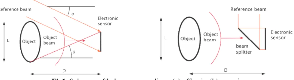
Digital holography seems more suited than ESPI for our purpose since it can deal either with scattering or specular surfaces. There are different configurations for recording hologram [1] [6] and which are shown in Fig1 : off-axis in which the reference beams is collimated and reaches the recording sensor at a certain angle, and on-axis where it is arrives normally to it.
Fig1. Schemes of hologram recording : (a) off-axis, (b) on-axis
The digital holography principle resides in the fact that one can compute the focused image of an object in any plane and without requiring a lens between the object and the sensor. The problem can be understood as if we know the complex amplitude of object wavefront in the sensor plane; we want to know its complex amplitude in the object plane. The relationship between both is described by the Kirchoff-Fresnel equation of Fourier optics. Let us consider the geometry shown in
Fig 2. Digital holographic geometry
Consider oi(x,y) the complex optical amplitude in the sensor plane. The complex amplitude oo(x’,y’) in the object plane and separated by a distance D along the optical axis is deduced by computing the Kirchoff-Fresnel propagation integral in the paraxial approximation.
oO(x', y')= exp ikD
{ }
iDλ exp ik 2D x' 2+y'2(
)
× dxdy∫∫
exp −2πiλD(xx'+yy') exp ik 2D(x 2+ y2) oi( )
x, y(1)
where λ is the wavelength,
k
= 2
π λ
, (x, y), (x’, y’) are the spatial variables. In practice we consider a discrete version of expression (1) in order to apply FFT algorithms. The Whittaker-Shannon allows determining the object reconstructed size L which is given by the pixel pitch ∆, and the object distance to sensor D :L = λ D/2∆ (2)
Taking into account the wavelength and the state-of-art pitch of sensors, the λ/∆ in visible application of Digital Holography is on the order of 0,05. In LWIR the pitch size of current sensors is on the order of 25 µm, what gives for a 10 µm laser, a λ/∆ ratio of 0,25. Therefore LWIR digital holography will allow reconstruction of field of view 5 times larger than in visible, which is a non negligible advantage.
A clear advantage of digital holography compared to classical interferometry is that it is not necessary that the object and the reference wavefronts match, therefore not requiring specific costly null lenses. The only condition is that the interference fringes have to be resolved in order to be usable in the reconstruction step. This opens up the way to observation of any reflector shapes with the same optical set-up (parabolic, elliptic, etc…) provide that the surface is illuminated in a correct way and that the reflected rays are impinging the sensor and interfere there with the reference wave. It is possible to place a collecting lens in front of the sensor (not necessarily imaging the object on it), just to allow collection of beams. Numerical reconstruction algorithms have to take into account the presence of such optical element.
The advantage of digital holography compared to its parent ESPI is that the phase is computed by isolating the argument of the reconstructed oo(x',y') function and not by applying the phase-shifting algorithm, as in
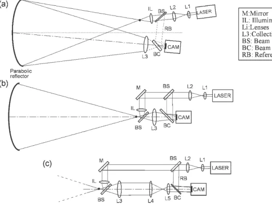
by suitable choice of lenses focal lengths. It must be noted that all the schemes presented do not use special lenses (such as null lenses) but well COTS elements.
Fig 3. Various schemes for digital holography with a parabolic test article ; (a) with off-axis illumination, (b) with on-axis illumination, (c) alternative to (b) for adaptable sampling of the object.
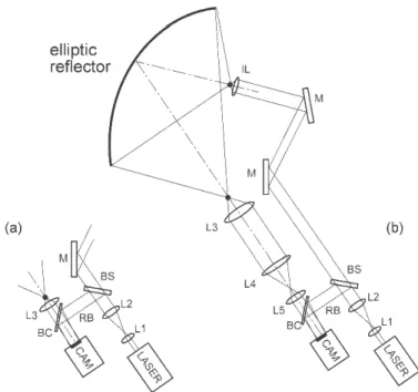
Presently a scheme similar to Fig 3(c) is studied for implementation with a parabolic shaped reflector. We are also studying the possibility of testing other types of reflector shapes with the same set-up and the minimum reconfigurable, still with COTS elements. Fig 4 shows the set-up adapted for an off-axis elliptic reflector. In this case, one must illuminate the test article by a suitable illumination lens (IL) which is placed at one focus and collecting rays through the second one. The problem we found here is that the illumination lens IL and the first lens of the imaging arm L3 are extremely open and it is not possible to have COTS components for these elements. Therefore we investigated other possibilities to deal with such more complex objects.
For that purpose we propose a new technique which consists in considering these objects as scattering instead of specular. Nevertheless it is not allowed to render them scattering by spraying removable scattering coating, what obliged us to find another way. The solution was already applied in the past by Hansen [7] whose aim was to use ESPI on mirror objects. He proposed to use an intermediate diffuser to illuminate the object and then one observes the image of the diffuser through the specular object, having so speckle "projected" onto the specular object. This technique was never applied with digital holography (only ESPI), moreover not in the LWIR domain. We present in the next section the study of this technique and its application to the case of the parabolic shaped reflector.
Fig 4. Schemes for digital holography with off-axis elliptic reflector (secondary PLANCK demo) III. PROJECTED SPECKLE (INTERMEDIATE DIFFUSER)
The set-up for speckle projection has been tested first with a small mirror object whose displacement is a rotation that can be countermeasured with an interferometer capable of angle measurement (HP interferometer). Fig 5(a) shows a scheme of the set-up. This is a classical lensless digital holography set-up with the reference beam in green and object beam in red. Here a diffuser is directly illuminated by the object beam. The angle θ between the reference beam and the normal of the mirror object determines the separation between the diffracted orders reconstructed numerically. Fig 5(b) shows the mirror object and Fig 5(c) the VarioCAM hr uncooled camera from Jenoptik without its objective lens.
Fig 5. (a) Projected speckle set-up with small reflector, (b) small mirror as target object, (c) the VarioCAM hr. Fig 6(a) shows the reconstruction of the real image (upper right corner) and its conjugate (bottom left corner) after application of FFT algorithm. A second hologram is stored electronically after rotation of the mirror object. The reconstruction is again applied and provides a new image similar to the first one. The phase of the object can be directly retrieved and after substraction of phases corresponding to the two object positions, one
Fig 6. (a) Reconstructed images : upper right the real image, bottom left : its phase conjugate. (b) Phase difference after rotation. (c) comparison of rotation measurement by digital holographic interferometry and
interferometer
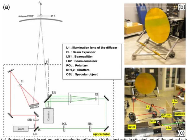
After having checked with small mirror object, we have used the set-up with a large parabolic reflector of around 6 meters focal length and 1.1 meter diameter. Fig 7(a) shows a drawing of the set-up, (b) in the front the set-up and in the background the parabolic reflector which is located out of the optical table. Fig 7(c) shows the reflector and its holder place on the lab floor.
Fig 7. (a) Projected speckle set-up with parabolic reflector, (b) the test article situated out of the optical table, (c) the set-up on the optical table with the reflector at 3 meters
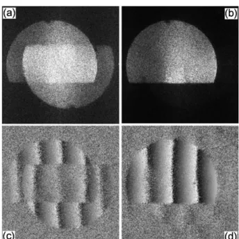
Fig 8(a) shows the reconstructed images of the parabolic antenna which is not entirely observable due to the vignetting by the optical table. Both the real and conjugate virtual images are superposed due to the fact that the image size overpasses the maximum possible one set by the Whittaker-Shannon theorem. In order to overcome
this and benefit from the entire resolution, one can apply phase-shifting to remove the phase conjugate image (Fig 8(b)) [8]. One can then compute the phase in both situations and after rotation of the antenna, one calculate the phase difference which is shown respectively in Fig 8(c) and (d). In the future we will improve the system in order to observe entirely the antenna and to adapt the parameters to fully benefit of the resolution of the image. Also we will use the same set-up for testing the off-axis ellisptic reflector.
Fig 8. (a) modulus of reconstructed image of antenna; (b) same with phase-shifting; (c) and (d) respective phase difference after rotation of antenna.
III. CONCLUSION
We have shown the preliminary results of a GSTP activity which studies digital holography for measuring displacement and deformation of space reflectors in vacuum-thermal balance tests, without requiring the development of costly null lens, as is the case with traditional interferometry. Digital holography can be envisaged in various set-up in order to cope with the specular characteristics of the test articles, even allowing measurements on more complicated cases such as off-axis elliptic reflectors.
REFERENCES
[1] T. Kreis, “Holographic Interferometry – Principles and Methods”, Vol. 1, Akademie Verlag, 1996. [2] C. Thizy, Y. Stockman, Ph. Lemaire, Y. Houbrechts, A. Mazzoli, M. Georges, E. Mazy, I. Tychon, D.
Doyle and G. Ulbrich, "Qualification of large reflectors in space environment with a holographic camera based on a BSO crystal", Trends in Optics and Photonics Series, Vol 99 on Photorefractive Effects,
Materials and Devices, G. Zhang, D. Kip, D. Nolte, J. Xu, eds., p.707-713 (2005)
[3] C. Thizy, Ph. Lemaire, M. Georges, P. Rochus, J-P. Colette, R. John, K. Seifart, H. Bergander, and G. Coe, "Comparison between finite element calculations and holographic interferometry measurements, of the thermo-mechanical behaviour of satellite structures in composite materials", Trends in Optics and
Photonics Series, Vol 99 on Photorefractive Effects, Materials and Devices, G. Zhang, D. Kip, D. Nolte, J. Xu, eds., p.700-706 (2005)
[4] J-F. Vandenrijt and M. Georges, "Electronic Speckle Pattern Interferometry and Digital Holographic Interferometry with Microbolometers Arrays at 10.6 microns", Applied Optics, in press.
[5] M. Georges, J-F. Vandenrijt. C. Thizy, Y. Stockman, I. Alexeenko, G. Pedrini and W. Osten, " Electronic speckle pattern interferometry in Long Wave Infrared: a new technique for combining temperature and displacement measurements. Applications in thermo-mechanical assessment of structures", International Conference on Space Optics, Rhodes, 4-8 Oct, Paper A2019756 (2010)
[6] P. Picart, J. Leval, "General theoretical formulation of image formation in digital Fresnel holography", J. Opt. Soc. Am. A 25, p. 1744-1761 (2008).
[7] R.S. Hansen, "A compact ESPI system for displacement measurements of specular reflecting or optical rough surfaces", Opt. Las. Eng 41, p. 73-80 (2004)
[8] I. Yamaguchi, J-I. Kato, S. Ohta and J. Mizuno, "Image formation in phase-shifting digital holography and applications to microscopy", Appl. Opt. 40(34), p.6177-6186 (2001)