UNIVERSITÉ DE MONTRÉAL
DOUBLE U-TUBE GEOTHERMAL BOREHOLE OPERATION UNDER
PHASE CHANGE CONDITIONS
PARHAM ESLAMI NEJAD
DÉPARTEMENT DE GÉNIE MÉCANIQUE ÉCOLE POLYTECHNIQUE DE MONTRÉAL
THÈSE PRÉSENTÉE EN VUE DE L’OBTENTION DU DIPLÔME DE PHILOSOPHIAE DOCTOR
(GÉNIE MÉCANIQUE) DÉCEMBRE 2011
UNIVERSITÉ DE MONTRÉAL
ÉCOLE POLYTECHNIQUE DE MONTRÉAL
Cette thèse intitulée:
DOUBLE U-TUBE GEOTHERMAL BOREHOLE OPERATION UNDER
PHASE CHANGE CONDITIONS
présentée par: ESLAMI NEJAD Parham
en vue de l’obtention du diplôme de : Philosophiae doctor a été dûment acceptée par le jury d’examen constitué de : M. PELLETIER Dominique, Ph.D., président
M. BERNIER Michel, Ph.D., membre et directeur de recherche M. MARCOTTE Denis, Ph.D., membre
M. YAVUZTURK Cenk Cy, Ph.D., membre
DÉDICACE
REMERCIEMENTS
I would like to convey my sincere gratitude to those who helped me to complete this study. First of all, I am genuinely grateful to my supervisor, Professor Michel Bernier, for his friendly guidance, substantial support, and precious advice. It was a great pleasure for me to work under his supervision. He was an endless source of encouragement to me throughout this period. His exceptional high standards inspired me to improve my skills throughout my research at École Polytechnique de Montréal. I am deeply indebted to him for his availability at any time for consultations and discussions on my research.
I take great pleasure in acknowledging all present and former students of my supervisor and of course my good friends, Ali Salim-Shirazi, Simon Chapuis, Antoine Langlois, and Yannick Allard, who created lots of memorable moments for me during these years and helped me to integrate into the group. I would also like to extend my thanks to Ali Salim-Shirazi for his assistance in calibrating the thermocouples used in my experiments.
I am deeply indebted to Professors B. R. Baliga and A. Teyssedou for the knowledge I acquired throughout their incredibly valuable lectures. I am also thankful to Professor M. Kummert for all the encouragement, support, and friendly advice I received from him.
I like to extend my thanks to the technical and administrative staff of the Mechanical Engineering Department. Special thank to Mr. Jean-Marie Béland for his marvellous work on my experimental set-up.
I made many friends in Montreal, and it gives me great pleasure to acknowledge the encouragement, support, and love that I received from them. They were with me in sad and happy moments and made all these years memorable for me. I refrain from acknowledging them individually because that would take many pages, and for fear that I may inadvertently miss some of them. However, I can not help mentioning the name of my best friends, Mahnaz, Ravid, Azin, Naser, Arezou, Alireza, Sara, Ali, Maryam and Farhad who were with me during the most tragic moment of my life when I lost my father.
I would like to thank colleagues of the “Course de Mardi” for bringing joy during days that I was doing experiments and writing my thesis. I had a wonderful jogging experience with them along Mont Royal Park which kept me physically and mentally in shape.
I owe special gratitude to my father and my mother for their pray, unconditional love, support, and encouragement throughout my entire life. I am deeply indebted to them for every success I have ever achieved. I wish my father was alive to see this moment that he was always hopping for. I would also thank my brother for his support, love, and guidance. He provided a great deal of encouragement to me during my bachelor studies and I am grateful to him.
I would like to send a heartfelt acknowledgement to my Family-in-law for the support and love I received from them.
I would also like to acknowledge Canada, the province of Québec, and École Polytechnique de Montréal for giving me the opportunity to continue my studies. It is with great pleasure that I express my thanks to Montrealers for their kindness.
I would like to convey my gratitude to Dr. Pelletier, Dr. Marcotte, and Dr. Yavuzturk for accepting to be a jury member.
The financial support provided by the NSERC Solar Building Research Network (SBRN) and Electricité de France, under the guidance of Dr. Odile Cauret, is greatly acknowledged.
Last, but most importantly, I would like to express my special gratitude to my lovely wife, Samira, for her patience, love, and support. She was an endless source of inspiration to me for achieving my goals. She was genuinely caring during these years and I am deeply indebted to her for every single second of our life.
Parham ESLAMI NEJAD
École Polytechnique de Montréal Montréal, Québec, Canada December 2011
RÉSUMÉ
Les systèmes de pompe à chaleurs couplées à des échangeurs géothermiques verticaux constituent des alternatives intéressantes pour la climatisation/chauffage des espaces et le chauffage de l'eau chaude en raison de leur haute efficacité et de leur faible impact sur l'environnement. Cependant, les coûts de forage demeurent un obstacle à leur utilisation généralisée. Les coûts de forage sont directement reliés à la profondeur des puits. Dans le cas d'installations avec puits unique, la profondeur dépend principalement de l'extraction maximale de la chaleur du sol pendant le pic des charges de chauffage du bâtiment.
Pour diminuer l’extraction maximale de chaleur du sol, il a été suggéré de recharger le sol en utilisant l'énergie solaire. Cependant, dans les installations à simple puits, l'injection de chaleur solaire ne réduit pas la longueur de forage de façon significative puisque l'injection solaire ne coïncide pas nécessairement avec le pic de charge du bâtiment. Par ailleurs, la chaleur solaire injectée se dissipe dans le sol sans faire augmenter la température du sol à proximité du puits de façon significative.
Dans ce projet, une nouvelle alternative est proposée pour réduire la longueur de forage dans les installations avec puits unique. Il s'agit d'une pompe à chaleur géothermique couplée avec un système solaire dont l'échangeur géothermique est constitué d’un puits à deux tubes en U avec deux circuits indépendants entouré par un anneau de sable saturé. Cette configuration est utilisée pour l'extraction de la chaleur dans un circuit, combiné avec une pompe à chaleur, et l'injection thermique dans l'autre circuit en utilisant l'énergie solaire. Dans cette configuration, l'échangeur géothermique agit comme un échangeur de chaleur entre le capteur solaire et la pompe à chaleur. Lors des périodes de pointe de chauffage du bâtiment, généralement la nuit lorsque l'énergie solaire n'est pas disponible, la pompe à chaleur extrait l'énergie du sol et, dans certains cas, le sable saturé gèle en formant un anneau autour du puits. Cela a pour effet de ralentir la baisse de la température de retour à la pompe à chaleur et tire parti de la teneur en énergie relativement élevée associée à la chaleur latente de fusion de l'eau dans le sable. Lorsque l'énergie solaire est disponible, la chaleur solaire est injectée dans le second tube en U pour faire fondre l'anneau de glace.
Pour évaluer précisément les conséquences de l'utilisation du système proposé, des modèles théoriques pour les puits et le sol sont développés dans cette étude. Le modèle du puits tient
compte des deux tubes en U avec deux circuits indépendants et le modèle numérique du sol permet de prédire le gel et le dégel de l'anneau de sable saturé autour du puits ainsi que le transfert de chaleur par conduction dans le sol.
Un modèle analytique est d'abord développé pour prédire le transfert de chaleur en régime permanent des puits à double tube en U sans l'anneau de sable saturé. Le modèle tient compte de la résistance thermique des tubes et de l'interaction thermique entre ceux-ci. Il permet de prédire les profils de température du fluide dans les deux circuits le long de la profondeur du puits, y compris la température des deux fluides en sortie. La nouvelle configuration de puits est évaluée en utilisant des simulations annuelles d'une pompe à chaleur pour un bâtiment résidentiel situé à Montréal. Les résultats indiquent que la recharge solaire hivernale en utilisant la configuration proposée réduit la quantité d'énergie extraite du sol de manière significative. Cependant, les diminutions de la longueur nécessaire du puits et de la consommation d'énergie de la pompe à chaleur sont relativement faibles.
Enfin, les conséquences thermiques du gel de l'anneau de sable saturé sont examinées. Un modèle numérique unidimensionnel radial est développé pour évaluer le transfert de chaleur de la paroi du puits vers le sol. Le modèle est en mesure de tenir compte de couches multiples du sol et le changement de phase est traité en utilisant la méthode des capacités thermiques équivalentes. Une installation expérimentale à échelle réduite a également été construite. Elle a été utilisée pour valider avec succès le modèle numérique. Ce modèle numérique du sol est par la suite combiné avec le modèle du puits afin d'examiner différents scénarios d'opération typiques. Les résultats montrent que la température de la paroi du puits demeure autour de 0 º C pendant plusieurs jours lorsque l'anneau de sable gèle alors qu'elle serait ramené à des valeurs beaucoup plus faibles sans la présence de l'anneau de sable saturé. Le gel est limité à quelques centimètres autour du puits. Lorsque l'énergie solaire est disponible, il est possible de faire fondre la glace et de «recharger» le sol pour le prochain cycle de gel. En utilisant cette approche, la profondeur du forage peut être réduite de 38% dans certains cas.
ABSTRACT
Conventional ground coupled heat pump systems with vertical ground heat exchangers constitute attractive alternatives for space conditioning and domestic hot water heating due to their high efficiency and environmental friendliness. However, borehole costs remain a barrier for their widespread utilization. Borehole costs are mainly driven by borehole depths which, in single borehole installations, are mainly dependent on peak ground load heat extraction during peak building heating loads.
To mitigate the peak ground heat removal, it has been suggested to recharge the ground using solar energy. However, in single borehole installations, solar heat injection does not reduce the borehole length significantly since solar energy injection is not necessarily coincident with the peak building load. Furthermore, the injected solar heat dissipates into the ground without making notable increases on ground temperature near the borehole.
In this work, a new solar assisted ground coupled heat pump alternative is proposed to reduce the borehole length in single borehole installations. The system under study consists of a double U-tube borehole with two independent circuits surrounded by a saturated sand ring. This configuration is used for heat extraction in one circuit, combined with a heat pump, and simultaneous thermal recharging in the other circuit using solar energy. In effect, it acts as a heat exchanger between the solar thermal collector and the heat pump. During peak building loads, usually at night when solar energy is unavailable, the heat pump extracts energy from the ground and in some cases the saturated sand freezes. This slows down the decrease in the return temperature to the heat pump and takes advantage of the relatively high energy content associated with the latent heat of fusion of water in the sand. When solar energy is available, solar heat is injected in the second U-tube to melt the frozen saturated ring.
To evaluate precisely the expected consequences of using the proposed system, theoretical models for the borehole and the ground are developed in this study. The borehole model accounts for the double U-tube with two independent circuits and the numerical ground model can handle freezing and thawing in the saturated region in the immediate vicinity of the borehole as well as pure conduction heat transfer in the ground.
An analytical model is first developed for the borehole to predict steady-state heat transfer in double U-tube geothermal boreholes without the saturated sand ring. The model accounts for fluid and pipe thermal resistance and thermal interaction among pipes, and it predicts the fluid temperature profiles in both circuits along the borehole depth, including the exit fluid temperature. The effect of the new borehole configuration is evaluated using annual simulations of a heat pump for a typical residential building located in Montreal. Results indicate that winter solar recharging using the proposed configuration reduces the amount of energy extracted from the ground significantly. However, the decreases in the required borehole length and heat pump energy consumption are relatively small.
Finally, the thermal consequences of freezing the saturated sand ring are examined. A one-dimensional radial numerical heat transfer model is developed to evaluate heat transfer from the borehole wall to the ground. The model can account for multiple ground layers and phase change is handled using the effective capacity method. A small-scale experimental set-up is also built. It was used to successfully validate the numerical model. The numerical ground model is combined with the borehole model to examine various scenarios involving typical heat pump operation. Results show that the borehole wall temperature remains around 0ºC for several days when the ground freezes while it would drop to much lower values without the presence of the saturated sand ring. Freezing is restricted to a few centimetres around the borehole. When solar energy is available, it is possible to melt the ice and "recharge" the ground for the next freezing cycle. Using this approach, borehole depth can be reduced by as much as 38% in some cases.
TABLE DES MATIÈRES
DÉDICACE... III REMERCIEMENTS ... IV RÉSUMÉ... VI ABSTRACT ... VIII TABLE DES MATIÈRES ... X LISTE DES TABLEAUX ... XIV LISTE DES FIGURES... XV LISTE DES SIGLES ET ABRÉVIATIONS ... XIX
INTRODUCTION... 1
CHAPITRE 1 LITERATURE REVIEW... 5
Overview ...5
1.1 Borehole and ground Models ...5
1.1.1 Analytical models...7
1.1.2 Numerical and combined numerical and analytical models...10
1.2 Ground Freezing...16
1.2.1 Artificial ground freezing for construction or mining purposes ...16
1.2.2 Natural freezing in soil around a buried pipeline ...18
1.2.3 Freezing in porous media ...18
1.2.4 Freezing in geothermal energy utilization...20
1.3 Ground Solar Recharging...23
CHAPITRE 2 OBJECTIVES AND THESIS ORGANISATION ... 29
2.1 Thesis objectives ...29
CHAPITRE 3 SCIENTIFIC ARTICLE 1: HEAT TRANSFER IN DOUBLE U-TUBE
BOREHOLES WITH TWO INDEPENDENT CIRCUITS... 32
Abstract ...32
3.1 Introduction ...32
3.2 Previous Studies ...34
3.3 Problem Formulation...37
3.4 Heat Flow Balance Equations ...39
3.5 Dimensionless Governing Equations and Boundary Conditions ...41
3.6 Laplace Transforms...42 3.7 Applications ...44 3.8 Conclusion...52 3.9 Nomenclature ...53 3.10 Appendix A ...55 3.11 Appendix B ...59 3.12 References ...61
CHAPITRE 4 SCIENTIFIC ARTICLE 2: COUPLING OF GEOTHERMAL HEAT PUMPS WITH THERMAL SOLAR COLLECTORS USING DOUBLE U-TUBE BOREHOLES WITH TWO INDEPENDENT CIRCUITS... 64
Abstract ...64
4.1 Introduction ...64
4.2 Literature Review ...65
4.3 Model Development ...69
4.4 Heat Flow Balance Equations ...70
4.5 Dimensionless Governing Equations and Boundary Conditions ...73
4.7 Applications ...75
4.8 Constant Inlet Conditions...75
4.9 Thermal Recharging over a Heating Season ...78
4.10 Conclusion...87
4.11 Nomenclature ...88
4.12 Appendix ...90
4.13 References ...92
CHAPITRE 5 SCIENTIFIC ARTICLE 3: FREEZING OF GEOTHERMAL BOREHOLE SURROUNDINGS: A NUMERICAL AND EXPERIMENTAL ASSESSMENT WITH APPLICATIONS ... 96 Abstract ...96 5.1 Introduction ...96 5.2 Literature review ...98 5.3 Model development...100 5.3.1 Ground model...100 5.3.2 Borehole model ...105 5.4 Experimental set-up...106 5.4.1 Axial symmetry ...109 5.4.2 Uncertainty analysis ...110
5.5 Ground model validation...111
5.5.1 First test case ...111
5.5.2 Second test case: Dry sand ...112
5.5.3 Third test case: saturated sand with freezing ...113
5.6 Applications ...115
5.8 Nomenclature ...124
5.9 Appendix ...126
5.10 References ...127
CHAPITRE 6 GENERAL DISCUSSION AND RECOMMENDATIONS ... 132
6.1 Review of the main contributions of this thesis ...132
6.2 Recommendation for future studies ...134
LIST OF REFERENCES ... 135
LISTE DES TABLEAUX
Table 3-1: Boundary conditions ...42
Table 3-2: Borehole characteristics...44
Table 4-1: Borehole characteristics...75
Table 4-2: Simulation results for the first and the last years and the average over 20 years ...82
Table 4-3: Simulation results for ground thermal conductivity of 1.5 and 3.0 W·m-1·K-1...87
Table 5-1: Positions of the thermocouples inside the sand-filled cylinder ...107
Table 5-2: Properties of the Ottawa sand (C-109) with a porosity of 0.36 ...109
Table 5-3: Borehole characteristics...117
Table 5-4: Results of annual simulations ...118
LISTE DES FIGURES
Figure1: Schematic representation of a GCHP system in heating and cooling mode...1
Figure 2: Schematic representation of a solar-assisted ground coupled heat pump system ...2
Figure 3: Schematic presentation of the proposed system ………..3
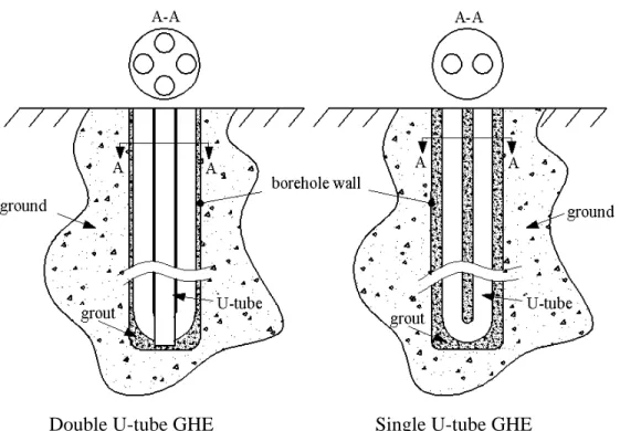
Figure 1-1: Schematic representation of single and double U-tube GHEs ...6
Figure 1-2: Borehole cross section...6
Figure 1-3: Schematic representation of the line source model ...7
Figure 1-4: Schematic representation of the finite line source model...7
Figure 1-5: Schematic representation of the cylindrical heat source model ...8
Figure 1-6: Cross section of a buried cable...8
Figure 1-7: Schematic representation of the model developed by Lamarche and Beauchamp (2007) ...9
Figure 1-8: Schematic representation of the model developed by Man et al. (2010) ...10
Figure 1-9: Schematic presentation of the numerical 2-D (radial-axial) calculation domain for the borehole and the surrounding ground...11
Figure 1-10: Schematic representation of the 3×3 bore field used by Bernier et al. (2004) ...12
Figure 1-11: Schematic representation of the pie-sector approximation ...13
Figure 1-12: Schematic presentation of single and double U-tube boreholes...14
Figure 1-13: Schematic representation of the multi-pole method geometry...15
Figure 1-14: Schematic representation of the 2-D model developed by Hashemi and Sliepcevich (1973) ...16
Figure 1-15: Schematic representation of the 2-D model developed by Lu and Wang (2008) ...18
Figure 1-16: Experimental set-up built to validate the 1-D numerical model of Weaver and Viskanta (1985) ...19
Figure 1-17: Rectangular cavity filled with water-saturated glass beads modeled numerically by
Rattanadecho and Wongwises (2008) ...20
Figure 1-18: Schematic representation of the geometry modeled by Mei and Emerson (1985) ...21
Figure 1-19: Schematic representation of the system studied by Chiasson and Yavuzturk (2003) ...24
Figure 1-20: Schematic presentation of the system studied by Ozgener and Hepbasli (2005) ...25
Figure 3-1: Schematic representation of conventional U-tube configurations ...33
Figure 3-2: Schematic representation of a double U-tube borehole with two independent circuits ...34
Figure 3-3: Cross section of a double U-tube borehole with two independent circuits ...37
Figure 3-4: Possible piping configurations ...38
Figure 3-5: Presentation of terms used in Eq. (3.1) ...39
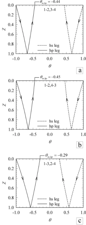
Figure 3-6: Borehole cross section for three different configurations ...43
Figure 3-7: Dimensionless temperature profiles along the borehole depth ...45
Figure 3-8: Local and cumulative heat exchanges for all three configurations ...46
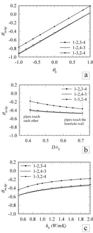
Figure 3-9: Impact of different parameters on borehole heat pump leg outlet temperature for different configurations ...47
Figure 3-10: Dimensionless temperature profiles along the borehole depth for m=0.05 kg/s and H=200 m...48
Figure 3-11: Fluid temperature profiles and borehole depth required to have Tin,hp=3.6°C for three configurations...50
Figure 3-12: Comparison of the required depth of independent double U-tube boreholes with single and parallel double U-tube boreholes under different conditions ...51
Figure 4-1: Schematic representation of the system under study...65
Figure 4-2: Schematic representation of conventional solar-assisted ground source heat pump system...67
Figure 4-3: Borehole cross-section showing the 1-3,2-4 configuration...69
Figure 4-4: Nomenclature used in Eq. (4.1)...71
Figure 4-5: Temperature difference between the inlet and outlet of both circuits as a function of α (m is kept constant)...76 hp Figure 4-6: Temperature profile and local and cumulative heat exchange along the borehole depth for different flow rate ratios ...77
Figure 4-7: Building heating load during the heating season...79
Figure 4-8: Heat pump capacity and corresponding compressor power requirement as a function of the inlet temperature. ...79
Figure 4-9: Schematic representation of three cases ...80
Figure 4-10: Heat pump inlet temperature (i.e. borehole outlet temperature) for all three cases for the first and last year of simulation ...84
Figure 4-11: Comparison between three cases over 24 hour period in winter...86
Figure 5-1: System configuration for the proposed system ...97
Figure 5-2: Illustration of the calculation domain and boundary conditions ...103
Figure 5-3: Finite control volumes...104
Figure 5-4: Four-pipe borehole cross section...106
Figure 5-5: Experimental set-up...108
Figure 5-6: Example of axial temperature uniformity ...109
Figure 5-7: Temperature profile for the first test case ...111
Figure 5-8: Temperature evolution for the second test case (dry sand) ...112
Figure 5-9: Temperature profile for the second test case (dry sand) ...113
Figure 5-10: Temperature evolution for the third test case (saturated sand with freezing) ...114
Figure 5-11: Temperature profile for the third test case (saturated sand with freezing)...114
Figure 5-13: Schematic representation of Cases 1 and 2 ...116 Figure 5-14: Borehole cross sections ...117 Figure 5-15: Tb, Tinhp, and the location of the freezing interface for cases 1b (a), and 2b (b)...119
Figure 5-16: Schematic representation of a sequence of events leading to two freezing interfaces at t = 2628 hr ...121 Figure 5-17: Optimum radius of the saturated ring for kg= 2 W·m-1·K-1...121
LISTE DES SIGLES ET ABRÉVIATIONS
2D Shank spacing between the U-tubes (m)a, b, c, d Dimensionless parameters, defined in Eq. (3.8) C Fluid specific heat (J·kg-1·K-1)
cs Soil specific heat (J·kg-1·K-1)
ci Ice specific heat (J·kg-1·K-1)
cw Water specific heat (J·kg-1·K-1)
G Solar radiation (W·m-2) , ,
ij ij ij
G G G Dimensionless parameters, defined in Eq. (4.A.1)
hi Fluid convective heat transfer coefficient, inside surface of the pipes (W·m-2·K-1)
H Required borehole length (m) k Thermal conductivity (W·m-1·K-1) kb Grout thermal conductivity (W·m-1·K-1)
kg Ground thermal conductivity (W·m-1·K-1)
kr Saturated sand ring thermal conductivity (W·m-1·K-1)
L Latent heat per unit mass (J·kg-1)
m Mass flow rate of the circulating fluid (kg·s-1)
N, S Two adjacent neighbours of a central control volume (shown in Figure 5-2) n, s Control volume faces (shown in Figure 5-2)
P Central control volume represented by node P (shown in Figure 5-2) p Laplace transform operator
qb Extracted energy from the ground (kWh)
qsolar Solar energy injected into the borehole (kWh)
rb Borehole radius (m)
rint Freezing interface radius in the saturated region (m)
rintmax Maximum radius of the frozen region (m)
rp Pipe external radius (m)
rsr Saturated sand ring radius (m)
R Thermal resistance, defined in Eq. (3.1) (m·K·W-1) R Thermal resistance, defined in Eq. (3.4) (m·K·W-1)
R
Dimensionless thermal resistanceRpipe Combined thermal resistance of the fluid and pipe wall (m·K·W-1)
Ta Ambient temperature (oC)
Tb Borehole wall temperature (oC)
Tf Fluid temperature (oC)
,
f f
T T Inlet fluid temperatures (oC)
Tinhp Inlet fluid temperature to the heat pump (oC)
Touths Outlet fluid temperature from the heat source (oC)
Tm Melting temperature (oC)
Tmean Solar collector mean fluid temperature (oC)
(UT)c Uncertainty of the temperature measurement (oC)
(UT)r Uncertainty associated with the probe location accuracy (oC)
Ur Uncertainty of the thermocouple tip location (m)
UT Global temperature uncertainty (oC)
Whp Annual heat pump energy consumption (kWh)
z Axial coordinate along the borehole depth (m) Z Dimensionless z coordinate
Δt Time interval (s)
Greek symbols
2δ Phase change temperature range (oC)
α Ratio of thermal capacities (defined in Eq. (4.9)) , , ,
Dimensionless parameters in Eq. (3.A.1)-(3.A.3)
,
Dimensionless parameters in Eq. (4.A.1) θ Dimensionless fluid temperature
Laplace transform of
Soil porosity
ρc Heat capacity (J·m-3·K-1)
ρsp Density of soil particles (kg·m-3)
ρw Density of water and ice (kg·m-3)
Subscripts
is bulk average values of the frozen regions ws bulk average values of the unfrozen regions 1-3 1-3 circuit in the 1-3,2-4 configuration 2-4 2-4 circuit in the 1-3,2-4 configuration
Abbreviations
1-D One-dimensional
2-D Two-dimensional
3-D Three-dimensional CHS Cylindrical heat source
DST Duct ground heat storage model GCHP Ground coupled heat pump
GHE Ground heat exchanger HDPE High density polyethylene LHEST Latent heat energy storage tank
SAGCHP Solar assisted ground coupled heat pump SCHP Solar coupled heat pump
INTRODUCTION
Ground coupled heat pump systems (GCHPs) are attractive alternatives to conventional air conditioning systems due to their high efficiency and environmental friendliness. This study concentrates on the ground part of GCHPs and more specifically on vertical ground heat exchangers (GHEs) as presented schematically in Figure 1. In heating mode, the heat pump extracts heat from the ground while in cooling mode it rejects heat to the ground. Typically, this can be accomplished with a coefficient of performance (COP) of about 3. With such a COP, in heating, two units of energy are collected from the ground and three are delivered in the house with one unit provided by the heat pump compressor.
Figure1: Schematic representation of a GCHP system in heating and cooling modes However, in heating dominated climates (e.g. Canada), the performance of the ground coupled heat pump decreases gradually over time. This is due to the fact that more heat is extracted from the ground than the amount rejected during the cooling season (if the heat pump is used for cooling). The ground temperature reduction in the vicinity of the borehole over the years results in a decrease in the inlet temperature to the heat pump, which translates into a reduction in the coefficient of performance (COP). In some extreme cases, for undersized boreholes, heat pumps cease to operate due to inlet temperatures that are below their recommended operating limit. Typically, two alternatives are used to avoid this situation. The first one is to use longer boreholes to overcome the peak building load of future years. However, high borehole drilling costs are often a barrier to the use of longer boreholes. The second alternative is to use an
auxiliary source of energy, electric heating, to supplement the heat pump output during peak building loads. This reduces the overall seasonal COP of the system.
Other alternatives have been examined to improve system performance and reduce borehole length. One such alternative uses a free and renewable source of energy such as solar energy to assist GCHP systems. These solar assisted ground coupled heat pumps (SAGCHPs) use solar heat to either increase the inlet temperature to the heat pump or to recharge the ground or a combination of the two.
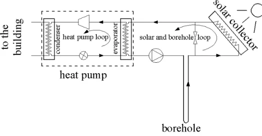
Figure 2: Schematic representation of a solar-assisted ground coupled heat pump system Figure 2 shows one possible configuration for a SAGCHP with an intermediate heat exchanger. Even though, the additional heat exchanger may add to the complexity of the system, several studies indicate that it is a viable option for multiple borehole installations in heating-dominated climates. However, in single borehole installations (typically for residential buildings), studies have shown that solar heat injection into the borehole does not reduce the borehole length significantly since it is not necessarily coincident with the peak building load. Furthermore, the injected solar heat dissipates into the ground without making notable increases on ground temperature near the borehole. Consequently, borehole length can not be reduced and the heat pump energy consumption reduction is minimal.
In this research, a new SAGCHP alternative is proposed to reduce the borehole length in single borehole installations. The system under study is presented schematically in Figure 3. It consists of a double U-tube borehole with two independent circuits surrounded by a saturated sand ring.
Figure 3: Schematic presentation of the proposed system
As shown in Figure 3, one circuit is linked to a heat pump and the other is connected to thermal solar collectors. In effect, the borehole in this configuration acts as a heat exchanger between the solar thermal collectors and the heat pump. Three modes of operation are possible: heat pump operation only, solar recharging with the heat pump off, and combined operation of the heat pump and solar collectors.
During peak building loads, usually at night when solar energy is unavailable, the heat pump extracts energy from the ground and in some cases the saturated sand freezes. This slows down the decrease in the return temperature to the heat pump and takes advantage of the relatively high energy content associated with the latent heat of fusion of water in the sand. When solar energy is available, solar heat is injected in the second U-tube to melt the frozen saturated ring and recharge the ground for the next freezing cycle.
To evaluate the merits of the proposed system, theoretical models for the borehole and the ground are developed in this study. The borehole model accounts for the double U-tube with two independent circuits configuration and the numerical ground model can handle freezing and thawing in the saturated region in the immediate vicinity of the borehole as well as the conduction heat transfer in the ground. A small-scale experimental set-up which mimics the behaviour of a geothermal borehole is built to validate the numerical model. Based on
temperature measurements in the sand, the numerical ground model is validated under freezing and non-freezing conditions.
Finally, the ground and borehole models are coupled and used in several simulations with real heat pump operation to evaluate the effects of this new system on borehole length and heat pump energy consumption. The optimum saturated sand ring radius is also evaluated for different ground thermal conductivites.
CHAPITRE 1
LITERATURE REVIEW
Overview
This study examines a borehole configuration for solar assisted ground coupled heat pump systems. It consists of two U-tubes with two independent fluid circuits. Solar collectors are connected to one circuit for solar recharging while the heat pump is linked to other circuit. The borehole is surrounded with a relatively small saturated (with water) region in its immediate vicinity. To our knowledge this configuration has not yet been studied. The following literature review describes previous work related to the modeling of geothermal boreholes, ground freezing, and solar recharging of geothermal boreholes.
1.1 Borehole and ground Models
Heat transfer to and from the ground in the vicinity of vertical ground heat exchangers (GHEs) is rather complicated. Several thermo-physical processes are involved such as multidimensional heat and moisture transfer, ground water movement, possible freezing and thawing, and frost expansion.
Several models have been developed for the design and simulation of vertical GHEs. However, each considered different assumptions to facilitate the calculations, particularly in geothermal engineering applications. This subsection describes briefly the existing models used to analyse vertical U-tube GHEs. Before introducing existing borehole and ground models, vertical U-tube borehole characteristics and configurations are presented here.
For vertical U-tube boreholes two major configurations are typically encountered, double U-tubes (popular in Europe) and single tubes (used in North-America) as shown in Figure 1-1. The U-tubes are made of high density polyethylene (HDPE) pipes with a U-bend at the end to reverse the direction of the flow. The space between the pipes and the borehole wall is usually filled with a grout. The grout is used to prevent contamination of aquifers and to augment heat transfer from the fluid to the ground. The circulating fluid flowing in the U-tubes is either water or a water-antifreeze mixture. The double U-tube configuration has a smaller borehole thermal resistance which usually leads to shorter boreholes.
Double U-tube GHE Single U-tube GHE
Figure 1-1: Schematic representation of single and double U-tube GHEs
A two dimensional horizontal cross section of a single U-tube borehole is presented schematically in Figure 1-2. It consists of two pipes with a center-to-center distance 2D, often called the shank spacing.
Figure 1-2: Borehole cross section
Due to the relatively high drilling cost of vertical GHEs, the initial investment associated to GCHP systems is relatively high. Therefore, it is important to estimate the required borehole length as accurately as possible. Several tools have been developed by many researchers to model the borehole and the ground in order to calculate the required length. These models are mainly based on analytical or numerical approaches.
1.1.1 Analytical models
One of the most basic transient analytical one-dimensional solutions that can be used for geothermal applications is the line source theory which was first proposed by Kelvin in 1882. Figure 1-3 presents schematically the line source model where the borehole geometry is neglected and approximated using an infinite line source or sink surrounded by an infinite homogeneous medium (ground). Pure heat conduction in the radial direction is solved in the ground. As reported by many researchers, ground temperature predictions using the line source equation are inaccurate for short time periods. For example, for a typical borehole, the line source equation is valid for times greater than approximately 10 hours.
Figure 1-3: Schematic representation of the line source model
Zeng et al. (2002) developed a finite line source model in a semi-infinite medium to evaluate more precisely the two-dimensional temperature response of the vertical boreholes (Figure 1-4).
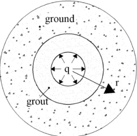
The other well-known one-dimensional analytical model is the cylindrical heat source (CHS) model for a finite diameter cylindrical source or sink embedded in an infinite homogeneous medium (Figure 1-5). The proposed solution (Carslaw and Jaeger, 1947) is a rather complicated indefinite integrals of Bessel functions. Ingersoll (1954) presented pre-calculated values for the integrals and used them for GCHP case studies.
Figure 1-5: Schematic representation of the cylindrical heat source model
A more complex model is the buried cable model developed by Carslaw and Jaeger (1947). It is an analytical model used to calculate the heat flow out of an infinite cable buried in the ground.
As shown in Figure 1-6, the cable, consist of multi layer cylinder with a metal core, insulation, and an outer protective sheath. The most significant difference between this model and the line source and cylindrical source is that it accounts for the thermal capacity of the core and the sheath. However, due to the high thermal conductivities of the core and the sheath, the thermal resistance of these regions is neglected. The insulation ring has a thermal resistance but its thermal capacity is neglected.
Young (2004) evaluated analytically the short time response of boreholes based on the “buried cable” solution. He replaced the core and the sheath in the buried cable model with the fluid and grout of real boreholes. Thus, the model accounts for the grout and the fluid thermal capacities. Furthermore, he placed the overall borehole thermal resistance between the grout and the fluid (insulation region of the buried cable model). In order to use the buried cable model for the single U-tube borehole configuration, equivalent borehole and pipe diameters are calculated. To improve the model, he moved part of the grout capacity to the core region (fluid) by defining a so called grout allocation factor. He compared his model against the line source model in an hourly annual simulation of a small office building. He concluded that the heat pump energy consumption calculated by the line source model is as accurate as his proposed model. However, he indicated that line source over predicts the peak outlet fluid temperatures from the borehole by as much as 1.3ºC for short duration peak loads.
Figure 1-7: Schematic representation of the model developed by Lamarche and Beauchamp (2007)
Lamarche and Beauchamp (2007) approximated the short-time response of single U-tube boreholes using an analytical solution to the unsteady one-dimensional heat conduction problem
of concentric annuli where the inner and the outer annuli represent the grout and the ground respectively. Better results for the short time response were reported compared to other analytical solutions since the model accounts for the heat capacity of the grout. An equivalent pipe diameter technique was used to approximate the U-tube configuration with a single pipe (Figure 1-7). Man et al. (2010) developed analytical models for both infinite (1-D) and finite (2-D) cylindrical heat sources. The model accounts for the heat capacity of boreholes by assuming a homogeneous medium for the whole calculation domain including the cylindrical region inside the heat source (Figure 1-8). The infinite heat source model was validated against the classical line source and “hollow” cylindrical source models.
Figure 1-8: Schematic representation of the model developed by Man et al. (2010)
1.1.2 Numerical and combined numerical and analytical models
Almost all analytical models do not account for the borehole geometry since this makes the task of finding a suitable analytical model impossible. They basically replace the boreholes with cylindrical or line heat sources or heat sinks to examine the heat transfer in the ground. In other words, thermal properties of the borehole elements, pipe thermal interactions in the borehole and borehole-to-borehole thermal interferences are not taken into account. Eskilson (1987) and Hellström (1991) are at the origin of some of the earlier works on detailed modeling of boreholes and bore fields. Eskilson calculated the temperature response of multiple boreholes based on
dimensionless temperature response factors, called g-functions. He used a combination of analytical and numerical techniques. The numerical model is transient and two dimensional in a radial-axial cylindrical coordinate system developed for a single borehole. The borehole thermal resistance and capacitance are neglected (see Figure 1-9 for schematic presentation of the calculation domain). A spatial superposition technique is used to obtain the response of the whole bore field.
Figure 1-9: Schematic presentation of the numerical 2-D (radial-axial) calculation domain for the borehole and the surrounding ground
Hellström derived steady-state two-dimensional analytical solutions for borehole thermal resistances with an arbitrary number of pipes. Theses solutions account for thermal interactions between pipes in the borehole. He also developed a well-known simulation model for seasonal thermal energy storage which is called duct ground heat storage model, or DST, (Hellström, 1989). This model is also a combination of analytical and numerical approaches for the borehole and the ground, respectively. The model predicts temperature distribution and heat transfer over the whole calculation domain. It accounts for multiple boreholes using superposition techniques. The DST model has been implemented in TRNSYS and is often considered to be a benchmark for other models.
For annual hourly simulation of GCHP systems, Bernier et al. (2004) developed an algorithm to aggregate heating/cooling loads in conjunction with the cylindrical heat source method. They referred to this algorithm as a “multiple load aggregation algorithm”. In order to reduce
calculation time, they used “past” and “immediate” thermal history periods. Immediate thermal history is not aggregated, while past thermal history is aggregated and subdivided into four time periods of the order of a day, a week, a month, and years. For single borehole installations, they performed an analysis to find a fixed duration for each period in order to have relatively accurate results as well as relatively short calculation time. For multiple boreholes in a bore field, a numerical two-dimensional model was developed to calculate the resulting temperature field. A schematic representation of the bore field used by Bernier et al. is shown in Figure 1-10. The model accounts for the borehole interaction using the temperature penalty concept. This temperature corrects the borehole wall temperature calculated based on the CHS model.
Figure 1-10: Schematic representation of the 3×3 bore field used by Bernier et al. (2004) Marcotte and Pasquier (a2008) used the fast Fourier transform (FFT) technique to evaluate the convolution product in time of incremental heat load and the analytical model response to a unit heat load. They also proposed a subsampling of the analytical function at a certain selected times according to a geometric sequence and then using good interpolation method such as cubic spline to obtain more reduction in computing time. They reported a reduction of one to two orders of magnitude in computing time compared to time-domain approaches with load aggregation.
Muraya (1995) used a transient two-dimensional finite element model for single U-tube boreholes to analyse thermal interaction between the U-tube legs. He defined a heat exchanger effectiveness to quantify thermal interaction. He also evaluated the equivalent diameter of a single tube at the borehole center that could produce the same heat transfer as a U-tube heat exchanger.
Rottmayer et al. (1997) developed a three-dimensional finite difference model for the simulation of a single vertical borehole and its neighbouring ground. This model is proposed for a single U-tube borehole but pipes in the borehole are approximated using “pie sectors”. The model accounts for fluid, pipe wall, and grout thermal resistance. To increase the calculation speed and thus reduce the simulation time, two time steps, one for the fluid transport and the other for the heat transfer to the ground, were used.
Wetter and Huber (1997) modeled the transient behaviour of a double U-tube borehole. However, they simplified the calculations by combining the pipes and treat them as a single element. They used a numerical model to simulate the ground next to the borehole while the outer boundaries of the simulation area was handled using the analytical line source approach. They accounted for variable heat extraction by superposing constant heat extraction starting at different time steps. They implemented this model into TRNSYS and it is known as Type 451.
Yavuzturk et al. (1999) developed a two-dimensional fully implicit finite volume model for single U-tube boreholes. They extended Eskilson’s work to calculate dimensionless temperature response factors, g-functions, for short time scales.
Figure 1-11: Schematic representation of the pie-sector approximation
The model accounts for thermal resistances of the grout and pipes, and the convective thermal resistance of the circulating fluid. Temperature variations along borehole depth and three-dimensional effects at the bottom of the U-tube and the ground surface are neglected. The cross section of the U-tube is approximated using “pie sectors” as shown in Figure 1-11. The pie-shaped wedge shown in this figure represents one leg of the U-tube.
Al-Khoury and Bonnier (2006) applied a three-dimensional finite element method to develop a transient flow and heat transfer model for double U-tube boreholes and the surrounding ground. The U-tubes were simulated using a single line (1-D) finite element representation. Both inlet temperatures are equal which implies a parallel arrangement for the double U-tubes.
Marcotte and Pasquier (b2008) proposed a so-called “p-linear” average temperature using a 3-D numerical simulation to evaluate the borehole thermal resistance from experimental data. They reported that the assumptions of constant heat flux along the borehole length or constant borehole wall temperature result in overestimated borehole thermal resistances. They also evaluated the economic impact of using overestimated borehole length in a case study with multiple boreholes. He et al. (2009) developed a finite-volume-based three dimensional model to simulate the short time scale dynamic behaviour of the circulating fluid as well as transient heat transfer in and around single U-tube boreholes. The model predicts a delay for the response of the outlet temperature to a step change of inlet temperature. Contrary to analytical and simplified numerical models, three-dimensional models cannot realistically be used in annual hourly GCHP system simulations. This is due to the fact that the time required for simulation of the whole system would be very long.
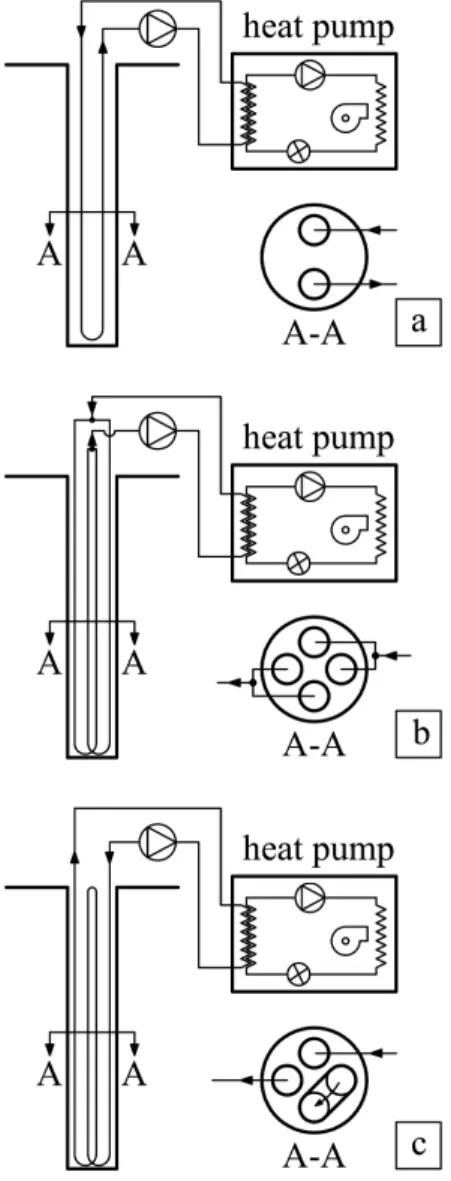
Zeng et al. (2003) used Hellström’s work to establish an analytical steady-state quasi-three dimensional model for single and double U-tube configurations arranged either in parallel or in series (see Figure 1-12).
Figure 1-12: Schematic presentation of single and double U-tube boreholes
Equivalent borehole thermal resistances were calculated for several combinations of circuit arrangements. The model accounts for thermal interaction between U-tube legs. Diao et al. (2004) combined this analytical borehole model and the finite-line source model developed by Zeng (2002) to predict heat transfer inside the borehole and in the ground.
In a review study, Lamarche et al. (2010) compared different existing approaches to calculate borehole thermal resistance including thermal short-circuit between pipes. They also performed an unsteady 3-D numerical simulation of a standard single U-tube borehole. A good agreement for the axial fluid temperature distribution of a single U-tube borehole was reported between the approach proposed by Zeng et al. (2003) and the three-dimensional simulation results.
Different studies were performed to calculate steady state borehole thermal resistances. For example, Bennet et al. (1987) developed the so-called “multi-pole” analytical solution method to solve the steady state two-dimensional heat conduction equation for pipes of different radii located inside a homogenous circular region. The circular region which represents the grout is surrounded by an outer homogenous circular region which represents the ground. They calculated temperature distribution as well as the steady state borehole thermal resistance based on a constant fluid temperature along the pipe. As shown in Figure 1-13, the multi-pole method is general and pipe symmetry is not required.
Figure 1-13: Schematic representation of the multi-pole method geometry
Steady state borehole thermal resistance was evaluated experimentally and numerically by Paul (1996). Shape factor correlations for single U-tube boreholes were developed to calculate steady state borehole thermal resistance as a function of the shank spacing, pipe diameter, borehole diameter, and grout thermal conductivity.
Gu and O'Neal (1998) calculated steady state borehole thermal resistances using an equivalent diameter method. They proposed an algebraic equation to approximate the single U-tube configuration using one circular pipe in the middle of the borehole. The circular pipe diameter (equivalent diameter) was calculated based on the diameter of the U-tube and shank spacing.
Remund (1999) proposed a set of relationships for different single U-tube borehole configurations to calculate the steady-state borehole thermal resistances based on conduction shape factors obtained from empirical data.
Al- Khoury and Bonnier (2005) developed a three-dimensional steady state flow and heat transfer model for single U-tube boreholes and the surrounding ground. The model accounts for ground water flow. Model validation did not correspond to the single U-tube borehole embedded in the ground. It was performed in two separate steps: examining heat flow in a 3-D ground structure without the borehole and examining heat flow in a single heat pipe.
1.2 Ground Freezing
Artificial ground freezing, which is commonly used for construction and mining purposes, has been reported in several studies. They mainly evaluated frost expansion, soil temperature distribution and required refrigeration capacity.
1.2.1 Artificial ground freezing for construction or mining purposes
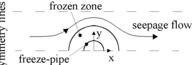
In an early study, Hashemi and Sliepcevich (1973) developed a 2-D numerical model to evaluate the effect of ground water flow (seepage flow) on artificial ground freezing. Mass and energy conservation equations as well as Darcy’s equation for unidirectional velocity field were solved simultaneously based on a finite difference method to calculate the temperature and velocity fields around a row of freeze-pipes.
Figure 1-14: Schematic representation of the 2-D model developed by Hashemi and Sliepcevich (1973)
The effective capacity method is used to account for the latent heat of the water. Bulk average values of thermal conductivity and specific heat of the wet soil vary with temperature in the calculation domain. The authors indicated that a relatively small ground water flow perpendicular
to the freeze-pipes axis has no significant effect on the ice interface growth in the horizontal direction.
Giudice et al. (1977) developed a 2-D finite-element ground freezing model to model freezing under roads. Different properties for frozen and unfrozen materials as well as different soil layers are considered in their study. However, water and soil elements are not specified separately and therefore the soil porosity did not appear in the formulations. Consequently, unfrozen and frozen soils are considered as two materials with their own thermal conductivity and heat capacity. An effective capacity method was used to handle the latent heat effect.
Newman and Wilson (1997) developed a 1-D model (in the ground depth direction) for freezing unsaturated soil. They combined heat and mass transfer equations by using freezing and soil-water characteristic curve data generated by other researchers. They calculated temperature evolutions as well as unfrozen water content and suction for the nodes positioned at or behind the frost front in the unfrozen soil region. Ice content values are computed using permeability versus suction relationships of unsaturated soil. They compared computed results with existing experimental results and good agreement was reported.
Frivik and Comini (1982) developed a 2-D finite element model of ground freezing in the presence of ground water flow for saturated soils. In this model, coupled velocity and temperature fields were calculated using energy and mass conservation equations. They accounted for the latent heat of fusion of water using a temperature dependent specific heat for the ground. A small convection contribution to the total energy transfer was reported due to a very low value of permeability. No ground water flow was assumed at the frozen soil region. An experimental set-up of a soil freezing plant was built to validate the computed results. Good agreement was found between predicted and measured temperature fields.
Mikkola and Hartikainen (2001) modeled the heat and mass transfer involved in freezing a saturated soil. They developed a 2-D model based on the mass, momentum, and energy conservation equations as well as entropy inequality equation for soil, water, and ice. The constitutive equations of the porous medium were derived based on the theory of mixtures with the concept of molar volume fractions and on the basic principles of continuum mechanics and macroscopic thermodynamics. The results were validated against 2-D experimental data and good agreement was reported.
Sres et al. (2006) and Sres and Anagnostou (2007) developed a 3-D numerical model based on the finite element method to evaluate freezing around concentric cylinder embedded in the ground. The model accounted for ground deformation and ground water flow. In this model, coupled temperature and velocity fields were calculated using the energy and mass conservation equations. The latent heat effect during freezing and thawing of the ground was handled using a temperature dependent specific heat of the soil. Simplified numerical techniques were implemented to increase computational efficiency. The results were validated against experimental data from a freezing process laboratory and showed a good agreement.
1.2.2 Natural freezing in soil around a buried pipeline
Lu and Wang (2008) developed a 2-D flow and heat transfer model for ground freezing around a buried crude oil pipeline during a shutdown period. . The model includes natural convection effects in the solidifying crude oil (Figure 1-15).
Figure 1-15: Schematic representation of the 2-D model developed by Lu and Wang (2008) The enthalpy method was used to calculate the temperature and flow fields as well as the frozen-unfrozen soil and crude oil interfaces. Mass, momentum, and energy conservation equations were discritized and solved using on a fully implicit finite difference scheme based on the control volume method.
1.2.3 Freezing in porous media
Since soils can be considered as a porous material, the methods used to handle solidification and melting in porous media can be applied for soil-water media as well. However, heat transfer modes in porous media can be different. Freezing and melting in a porous medium is commonly classified into three categories; pure conduction, combined conduction and forced convection,
and combined conduction and natural convection models. Pure conduction and combined conduction and natural convection models are of interest to this study and a few studies in these areas will now be reviewed.
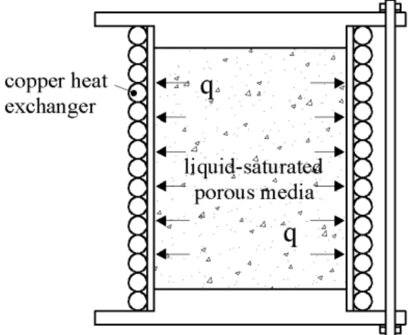
Weaver and Viskanta (1985) performed a 1-D numerical study of the solidification of saturated porous media in a cylindrical capsule. Heat is extracted from the outer surface of the capsule using a copper heat exchanger wrapped and soldered around the outside of the capsule (see Figure 1-16).
Figure 1-16: Experimental set-up built to validate the 1-D numerical model of Weaver and Viskanta (1985)
The pure conduction energy equation for the solid and liquid are solved based on a finite difference method for a fixed grid system. The latent heat effect is taken into account using an interfacial energy balance equation. The effective thermal conductivity of the porous media and of the phase change material (PCM) is calculated using empirical formulations. An experimental validation for water-glass beads and water-aluminum beads, were performed and good agreement between predicted and measured data for the water-glass beads is reported. However, due to large differences between the properties of aluminum and water, the local temperature equilibrium assumption was violated and poor agreement was reported for the water-aluminum beads.
Wang et al. (1990) evaluated the effect of natural convection on solidification of a superheated liquid-saturated porous media around a cold vertical cylinder. A 2-D model was developed to solve the energy equation in the solid and liquid regions, the momentum equations in the liquid region and the energy balance equation at the solid-liquid interface. Thicknesses of the frozen layer, temperature distributions, and velocity fields were obtained. The energy equation in the
solid region around cylinder was solved in the cylindrical coordinate systems while the Cartesian coordinate system was used in the liquid region. Consequently, the radial curvature effects were neglected in the liquid region. The authors did not validate the predicted values against experimental data. They reported significant convection effects under high values of the Rayleigh numbers and liquid superheat.
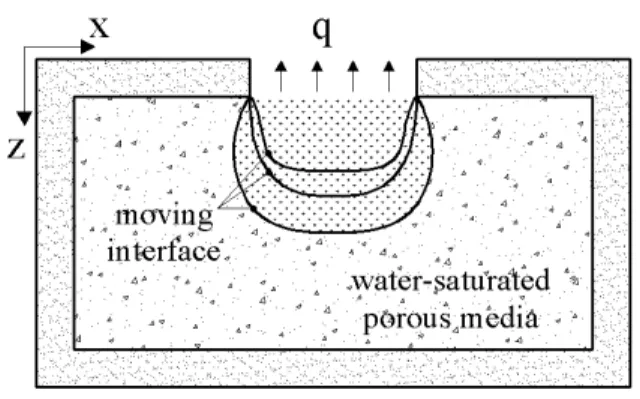
Rattanadecho and Wongwises (2008) developed a 2-D freezing model of water-saturated porous media using a moving mesh technique. The unsteady conduction equation was solved iteratively together with a moving boundary condition using an implicit-finite difference method. A rectangular cavity filled with water-saturated glass beads was modeled with different boundary conditions (see Figure 1-17). Bulk average values of thermal conductivity, density, and thermal heat capacity for two frozen and unfrozen regions were considered. Predicted values were validated against experimental measurements and available analytical solution and good agreement was reported.
Figure 1-17: Rectangular cavity filled with water-saturated glass beads modeled numerically by Rattanadecho and Wongwises (2008)
1.2.4 Freezing in geothermal energy utilization
A few researchers evaluated the effect of groundwater advection on boreholes and GCHP performance and a few studies have also developed models to account for ground freezing in geothermal energy utilization. However none of them focused on ground freezing effects on system performance. Furthermore, they have not evaluated the effect of ground freezing on borehole length reduction.
For example Diao et al. (2004) developed an analytical model based on the line source approximation to account for coupled conduction and advection in a saturated soil but without
any change of phase. Wang et al. (a2009) conducted a thermal performance experiment of a borehole under groundwater flow in a city in China. A simplified theoretical model was developed to estimate the characteristics of the groundwater flow based on ground temperature profile measurements. Raymond et al. (2011) developed a method to analyze thermal response tests under more realistic conditions such as significant groundwater flow, high geothermal gradient, or heterogeneous distribution of surface properties.
Mei and Emerson (1985) are at the origin of some of the earlier works on modeling ground freezing in geothermal applications. They developed a numerical 1-D flow and heat transfer model for buried horizontal single coil connected to a heat pump.
Figure 1-18: Schematic representation of the geometry modeled by Mei and Emerson (1985) The model accounted for heat pump cyclic operation and ground freezing around the coil. The governing equations are coupled using the boundary conditions at the outer pipe surface and at the frozen/unfrozen interface. Results indicated that when the fluid inlet temperature is much lower than the ground freezing point, the total energy extracted from the ground comes mainly from the latent heat of fusion of the water in the ground.
Fukusako and Seki (1986) investigated the heat transfer characteristics of a concentric-tube thermosyphon connected to a heat pump. The concentric-tube thermosyphon was placed vertically in the ground to exchange thermal energy by free convection of the working fluid. Momentum and energy equations in the pipe and annulus were solved as well as the heat conduction equation in the ground for both the frozen and unfrozen regions by using a
finite-difference method. The model accounted for the latent heat effect using an energy balance equation at the annulus wall and at the frozen area interface.
Fan et al. (2007) developed a model to evaluate the impact of groundwater advection on the borehole and GCHP performance. The model accounted for a 2-D heat conduction and unidirectional groundwater advection in a saturated ground. Multiple boreholes in a bore field were considered while each borehole was approximated using an equivalent single pipe. The latent heat of fusion of the ground water was accounted for using an inner source term in the energy conservation equation. The results indicated that a relatively high ground water flow has a significant impact on the ground temperature field and the working fluid temperature. However, the effect of ground freezing on system design and performance was not evaluated in this study. Nordell and Alström (2006) reported that in certain unusual cases, water-filled borehole freezing causes a high pressure that deforms the pipes in the borehole thus stopping the working fluid circulation. They also suggested some solutions such as replacing the water with cement or sand to solve the problem.
Marcotte et al. (2010) examined the effects of axial heat conduction by comparing the results obtained using the finite and infinite line source method. In one of their test cases they evaluated the effect of axial heat conduction on the energy required to freeze the ground for environmental purposes.
Recently, Fontaine et al. (2011) combined steady state results for fluid temperature inside horizontal pipes and transient ground temperature calculated based on the finite line source to develop a complete heat transfer model for both the fluid and the ground. The model accounts for phase change in the ground. A case study of horizontal pipes with spiral pattern was studied. The effect of different parameters of the borehole such as length, spacing and buried depth on the amount of heat extracted from the ground and on the ground temperature was evaluated. Results indicated that increasing length, spacing and buried depth increases the amount of energy extracted from the ground. Furthermore, they concluded that increasing buried depth can keep the ground frozen around the pipes while increasing length and spacing enhances the risk of thawing around the pipes.
1.3 Ground Solar Recharging
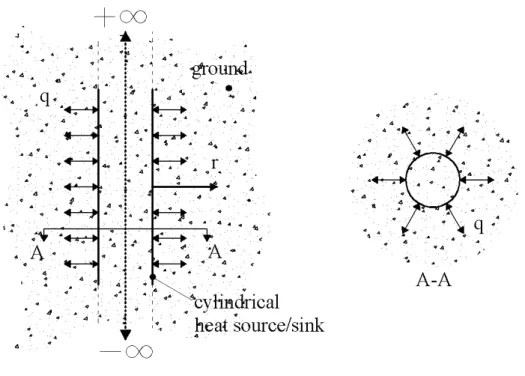
Despite the fact that GCHP systems are attractive options for heating and cooling applications, several studies have reported that in heating dominated climates, the performance of conventional GCHP system decreases gradually over time. This is due to the fact that the ground temperature in the vicinity of the borehole decreases over the years since more heat is extracted from the ground than the amount rejected during the cooling season. Bernier (2000) indicated that for a typical constant heat extraction of 37.5 W/m, the borehole wall temperature decreases by approximately 5ºC over a 24 hour period. Trillat-Berdal et al. (2007) also reported a reduction of 2ºC of the soil temperature in the vicinity of double U-tube borehole over twenty years of heat pump operation. The ground temperature reduction results in a decrease in the inlet temperature to the heat pump which translates into a reduction in the coefficient of performance (COP). One possible strategy to increase the ground temperature is to combine a supplementary source of energy such as solar energy with conventional GCHP systems. These systems are usually known as solar assisted ground coupled heat pump (SAGCHP) systems or hybrid GCHP systems. This idea was first introduced by Penrod and Prasanna (1962, 1969) who proposed a system that utilizes both solar collectors and the ground as the heat source for the heat pump. In other words, they let the ground temperature recover from heat extraction by using available solar energy. In a more recent study performed by Yang et al. (2006) a numerical simulation was conducted to find the optimum operating time of ground coupled heat pump (GCHP) and solar coupled heat pump (SCHP) systems in alternate operation mode. A vertical geothermal borehole was approximated by an equivalent cylindrical heat source/sink and the heat transfer process in the borehole surrounding was calculated using a 2-D heat conduction model. The optimum heat pump operation time was obtained based on the mean earth temperature at the end of the GCHP off period and system monetary savings. They recommended using the SCHP and GCHP systems alternately for a period of 10-14 hours a day to achieve a 30-60% recovery-rate for the ground temperature. They also evaluated different alternatives for combination of geothermal boreholes, solar collector, and heat pump. Results indicated that solar heat injection into the borehole is one of the energy efficient options.
The other possible strategy to increase the ground temperature is to inject heat into the ground using geothermal boreholes. Many researchers indicated that recharging the ground is a viable