HAL Id: hal-03027651
https://hal.archives-ouvertes.fr/hal-03027651v3
Submitted on 27 Nov 2020
HAL is a multi-disciplinary open access
archive for the deposit and dissemination of
sci-entific research documents, whether they are
pub-lished or not. The documents may come from
teaching and research institutions in France or
abroad, or from public or private research centers.
L’archive ouverte pluridisciplinaire HAL, est
destinée au dépôt et à la diffusion de documents
scientifiques de niveau recherche, publiés ou non,
émanant des établissements d’enseignement et de
recherche français ou étrangers, des laboratoires
publics ou privés.
On the Reconfiguration of Cable-Driven Parallel Robots
with Multiple Mobile Cranes
Hor Tan, Latifah Nurahmi, Bambang Pramujati, Stéphane Caro
To cite this version:
Hor Tan, Latifah Nurahmi, Bambang Pramujati, Stéphane Caro. On the Reconfiguration of
Cable-Driven Parallel Robots with Multiple Mobile Cranes. The 5th International Conference on Robotics
and Automation Engineering, Nov 2020, Singapore, Singapore. �hal-03027651v3�
On the Reconfiguration of Cable-Driven Parallel Robots with Multiple Mobile
Cranes
Hor Tan, Latifah Nurahmi, Bambang Pramujati
Department of Mechanical EngineeringInstitut Teknologi Sepuluh Nopember Sukolilo Surabaya 60111, Indonesia e-mail: [email protected],
[email protected], [email protected]
Stéphane Caro
CNRS, Laboratoire des Sciences du Numérique de Nantes, UMR CNRS 6004
1 Rue de la Noë 44321, Nantes, France e-mail: [email protected]
Abstract—This paper proposes a Cable-Driven Parallel Robot
(CDPR) with three mobile cranes for search-and-rescue operations. Each mobile crane is composed of a reconfigurable telescopic boom, which can rotate. A cable is mounted from the tip of the telescopic boom to the end-effector. The locations of mobile cranes are fixed, but the configuration of the telescopic boom can be adjusted to enlarge the workspace and to maintain the overall system in equilibrium. The static equilibrium of end-effector and mobile cranes is initially studied to determine the cable tension distribution and wrench-feasible-workspace. To guarantee all mobile cranes to be always in a static equilibrium when executing a given task, the telescopic booms are reconfigured. Three case studies for the reconfigurable CDPR with multiple mobile cranes are presented to compare the tension distribution and workspace size.
Keywords—Cable-driven parallel robot, tension distribution, static equilibrium, zero-moment-point, reconfigurable, mobile cranes.
I. INTRODUCTION
Cable-Driven Parallel Robot (CDPR) has been developed for both academic and industrial purposes [1]. Various applications of CDPR have been employed in the industrial field, or and some prototypes have been fabricated such as IPAnema [2]. Another type of suspended CDPR was developed in [3,4] for a rapid-life scan. A set of cable arrangements was analyzed and pulleys orientation was reconfigured to adjust the tension value and to increase the manipulator workspace. The prototype has been developed with a cube base frame 0.8m0.8m0.8m[5].
A mobile CDPR was developed in the framework of the ECHORD++ FASTKIT project for the industrial requirement with fast pick-and-place operations [6,7]. A planar Mobile-CDPR (M-CDPR) was proposed in [8] by using two mobile bases and each mobile base has two cables. The mobile base must be stable during the moving platform movement; hence Zero Moment Point (ZMP) was applied to analyze mobile base stability [9].
Inverse Kinematics, static equilibrium, dynamics, stiffness, and the workspace of CDPR were investigated in [10]. The methodology to trace the
Wrench-Feasible-Workspace (WFW) based on Available-Wrench-Set (AWS) was proposed [11,12]. In [13], the distribution of cable tensions was shown along with a number of trajectories of the end-effector, for example, horizontal or spherical trajectories.
This paper aims to develop a CDPR with three mobile cranes for search-and-rescue operations. Distribution of cable tensions and mobile cranes stability during reconfiguration are the main focus of this paper. The workspace of the end-effector is considered as wrench feasible workspace (WFW).
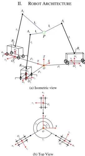
II. ROBOT ARCHITECTURE
P 1 u 1 v w1 3 u 3 v 3 w 2 u 2 O 2 w X Y Z 2 v 1 O 3 O O 2 l 3 l 1 l 2 3 1 3 B 1 B 2 A 2 B 3 A 2 r 3 r 1 A 1 r
(a) Isometric view
3 1 X Y 2 v 3 v 3 u O 3 O 2 1 u 1 v 1 O 2 u 2 O (b) Top View
The robot consists of three mobile cranes with mobile coordinate (u v w ) attached at the origin j, j, j Oj and its top view is shown in Fig. 1(a)-(b), respectively. Each mobile crane is located at the origin of the local coordinate Oj with distance j from the origin of the fixed frame and the angle
j
that is measured counterclockwise from the X-axis as demonstrated in Fig. 1(b). The fixed coordinate frame of origin O and axes (X, Y, Z) is located at the ground center. rj and j are the telescopic boom length and tilt angle of the mobile cranes (j =1, 2, 3), respectively. At point Bj , the telescopic boom can rotate with an angle j about the axis
j
w . The end-effector is considered to be a point mass P, of cartesian coordinate vectorp=[ ] .x y zT The exit point
j
A is located at the tip of the telescopic boom and linked to point P by one cable. The vector b
j
a of Aj is with respect to fixed
coordinate.
Point Bj is located at the base of the telescopic boom and it is a point connecting the mobile crane j to the telescopic boom. z
j
b is the height of the mobile cranes. The
cable length vector points from point P to pointAj , as:
b b
j = j−
l a p . Accordingly, the unit vector of each cable b
j u is computed as follows: b j b j b j = l u l ()
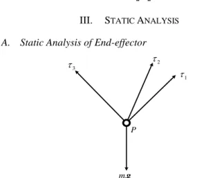
III. STATIC ANALYSIS A. Static Analysis of End-effector
P 2 1 3 . m g
Figure 2. Free-body diagram of an end-effector
In this section, the cables are assumed to be non-elastic and massless. According to the free-body diagram of end-effector at point P shown in Fig. 2, the equation of static equilibrium at point P is expressed as:
0
e
+ =
W w ()
where
=
1 2
3
T is the cable tensions vector, and [0, 0, ]Te = −mg
w is the gravitational force acting at point mass P. The gravity vector is denoted as g=
0, 0,−g
Tand Wrench matrix is defined as following:1 2 3
b b b
=
W u u u ()
Since, W is square matrix, the cable tensions can be computed as follows: 1
e
= −W w , as long as matrix W is −
not singular. Then, the cable force fj can be expressed as:
b
j = − jj
f u . Each cable tension is maintained to be positive and greater than 1N all the time.
B. Static Analysis of the Mobile Cranes
Three mobile cranes are fixed on the ground and they altogether should satisfy the condition of static equilibrium. The free-body diagram of the j-th mobile crane is illustrated in Fig. 3. Each mobile crane has four jack floats to lift the mobile cranes when the end-effector is performing some tasks. The jack floats have a contact point with the ground at points C1j,C2j,C3j,C . The reaction forces at these contact 4j
points fr j1 ,fr j2 ,fr j3 ,fr j4 are the main role in the static analysis of the mobile cranes. As a consequence, the static equilibrium of the mobile cranes can be mathematically derived for two conditions, namely tipping and rolling. The mobile crane is said to be tipping if it turns over about the
.
j
v It occurs because the frontal reaction forces (fr j1 and fr j4 ) are very high and the rear reaction forces (fr j2 and fr j3 ) are null. The frontal and rear reaction forces can be written respectively, as follows:
1 4 frj = r j+ r j f f f () 2 3 rrj = r j+ r j f f f ()
By using Newton's first law of motion, the forces equilibrium and moment at point O are defined as follows:
0 . . 0 frj rrj mI mII j = + + + + =
f f f g g f () 0 . . 0 O b b b frj frj rrj rrj j j I j II j M m m = + + + + =
c f c f a f e g h g ()where m and I m are masses of the telescopic boom and II
mobile crane and their gravitational forces are acting at points Ej and Hj, respectively, as shown in Fig. 3(a). h and bj
b j
e are the position vector of the center of gravity Hj and
telescopic boom point Ej. cfrjand crrjare the position vector
from the origin O to the frontal and rear sides of the mobile crane as shown in Fig. 3(b). The mobile crane is said to be rolling if it turns over about the axis uj. It happens since the right reaction forces (fr j1 andfr j2 ) are very high and the left reaction forces (fr j3 and fr j4 ) are null or vice versa. Accordingly, the right and left reaction forces are respectively defined as follows:
1 2 rgj = r j+ r j f f f () 3 4 lfj = r j+ r j f f f ()
The forces equilibrium and moment at point O is written as:
0 . . 0 rgj lfj mI mII j = + + + + =
f f f g g f () 0 . . 0 O b b b rgj rgj lfj lfj j j I j II j M m m = + + + + =
c f c f a f e g h g ()where clfj is the vector position from the origin O to the
mid-point between mid-points C3j and C4j. The vector position crgj
point from origin O to the mid-point between points C1j and
C2j as shown in Fig. 3(b).
IV. ZERO MOMENT POINT
j O i w j v j u j B j j f 1 j C 4 j C 2 j C 3 j C 3 r j f 2 r j f 4 r j f 1 r j f u j d v j d j A j H j E j r . I m g . II m g Z X Y O
(a) Isometric view
j v j u j O j A j lfj C j − Crrj rgj C frj C (b) Top View
Figure 3. Free-body diagram of a mobile crane
Zero Moment Point (ZMP) is a concept to evaluate the robot stability. When a mobile robot executing a given task, it has a ground contact point that is tangent to the ground surface [14]. In this paper, ZMP is defined as a point within the mobile cranes where the sum of moments due to frontal and rear reaction forces is null for tipping; and the sum of moments due to right and left reaction forces are null for rolling. ZMP is computed in the mobile coordinate (u v wj, j, j), hence the Cartesian coordinates of Aj should be expressed into the mobile frame. As a result, the sum of moments at the point Oj can be formulated for tipping
analysis, as follows:
( ) 0
oj frj rrj j
M + f +f d = ()
where dj is a vector that donates the ZMP of mobile frame. The mobile crane will not tip about the vj , which means that ZMP will be within the points C1 j to C2 j or within the length d as shown in Fig. 3(a). By solving Eq. (12), the uj
length d can be determined as: uj
(
wj. ju) (
uj. jw) (
I.e .guj)
u j w w frj rrj a f a f m d f f − − = + ()The sum of the moment at point O can be formulated for rolling analysis, as follow:
( ) 0
oj lfj rgj j
M + f +f d = ()
The mobile crane will not roll about the axis uj, which means that ZMP will be within the points C1 j and C4 j or within the length v
j
d as shown in Fig. 3(a). By solving
Eq. (14), the length v j
d can be determined as:
(
vj. jw) (
wj. jv) (
I.e .gvj)
v j w w lfi rgi a f a f m d f f + − = + ()Accordingly, the mobile cranes will be statically stable if and only if the lengths d and uj d are the dimension of the vj
mobile cranes.
V. RECONFIGURATION PLANNING
Reconfiguration is conducted by extending/retracting the length of the telescopic boom (rj) and orientating pitch and/or yaw angles (j and j), as shown in Fig. 3. One non-reconfiguration case and three reconfiguration plans are proposed as follows: • Plan 0: 1 , 0, 105o j j j r = m = = • Plan 1: 105o j
= , rj and j are reconfigured • Plan 2: j = , 0 rj and j are reconfigured • Plan 3: rj,j and j are reconfigured.
Three mobile cranes are located symmetrically with respect to origin O. They form an equilateral triangle such that 1=330o
2 90
o
= and 3 =210oas shown in Fig. 1.
The distance of each mobile crane to origin O is j =3m. The tracking of end-effector will be evaluated along the pick-and-place trajectory. The quadratic curve with two x-intercepts has been selected to be the trajectory and the equation is written as follows:
2 -0 3( ) A B B x x x y z x x x = = = − + () For all plans, the end-effector starts from the initial point
0
A
x = at point A with time t=0 to the desired point
0.5
B
VI. RESULTS AND DISCUSSIONS
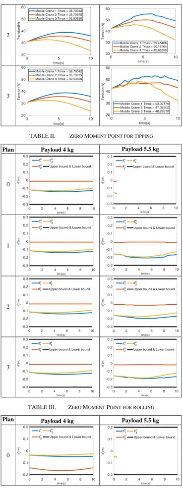
WFW is said to be a set of poses of end-effector that can maintain the static equilibrium of the mobile cranes and positive cable tension under external force. The workspace of Plan 0 is shown in Fig. 4. By increasing the payload, the cable tension will also increase then the mobile cranes will be unstable and the workspace is smaller as shown in Fig. 4(b). Base on the result of ZMP of Plan 0 in TABLE III, the mobile cranes cannot handle a payload of 5.5 kg, hence, the second mobile crane will be roll-over as shown in this link0F0F0F
1 . Therefore, the concept of reconfiguration is introduced and will be analyzed hereafter
(a) WFW
(b) Tipping/rolling-free workspace Figure 4. Workspace of Plan 0 TABLE I. TENSION DISTRIBUTION Plan Payload 4 kg Payload 5.5 kg
0 1 1Plan 0: https://itsacid-my.sharepoint.com/:v:/g/personal/210000011_staff_integra_its_ac_id/EV WC4CGKbF9Eu_tyhfw98nABjJPF5oLb_9VyglmLJVHzxg?e=u14yDk 2 3
TABLE II. ZERO MOMENT POINT FOR TIPPING Plan Payload 4 kg Payload 5.5 kg
0
1
2
3
TABLE III. ZERO MOMENT POINT FOR ROLLING Plan Payload 4 kg Payload 5.5 kg
1
2
3
As shown in TABLE I, the cable tensions begin at the initial point with the same value as the desired point for payload 4kg. However, if the payload is increased to be 5.5kg, mobile cranes of Plan 0 will not be able to handle the great value of cable tensions and become unstable at t~1s. Reconfigurable of the telescopic boom, the end-effector can follow the trajectory without turning over of the mobile cranes. Plan 3 is the best plan, the maximum cable tension of the first and second mobile crane is lower compared to Plan 1 and Plan 2. However, the third mobile crane is highest because rj,j and j is changed together when giving a
task. The animation of the reconfigurable telescopic boom can be seen in these links: Plan 11F1F1F
2 Plan 2 2F2F2F
3 and Plan 3 3F3F3F
4. ZMP analysis is illustrated in TABLE II for tipping and TABLE III for rolling. For Plan 0, We can recognize that the second mobile cranes will be rolling because d2v payload 5.5kg rapidly increases to the lower bound. The second mobile crane is not turned over because the value of d2v reconfiguration telescopic boom is in the limitation of ZMP.
VII. CONCLUSIONS
This paper proposed a mathematical model of CDPR with multiple mobile cranes. The reconfigurable telescopic boom is attached at the top of mobile cranes. The location of the mobile crane is fixed, while the telescopic boom can be reconfigured. The end-effector and mobile crane are maintained in a static equilibrium; hence WFW can be 2Plan 1: https://itsacid-my.sharepoint.com/:v:/g/personal/210000011_staff_integra_its_ac_id/Ee_d _Zzi4RREkF_0A53i8RQBeY1CmKnSh1o2XSHNP3jO7A?e=DWBB10 3Plan 2: https://itsacid-my.sharepoint.com/:v:/g/personal/210000011_staff_integra_its_ac_id/Eat0 V2pJYZtFmTbmwLsHJl8BDn4oS0yeo2MmjmIQzpn81Q?e=sKHfuB 4Plan 3: https://itsacid-my.sharepoint.com/:v:/g/personal/210000011_staff_integra_its_ac_id/EU4 4Jf3wvgpNqLyImzG_w1MBsLomKHZgaOTaRNOBp6P18w?e=xZVZTQ
determined. The results showed that cable tension values along Plan 1 and Plan 2 are higher than those obtained along Plan 3. The cable tension is also having a significant effect on the stability of the mobile cranes. ZMP defined the stability of the mobile crane and we can recognize that the mobile cranes will be tipping/rolling-over if the payload is increased.
ACKNOWLEDGMENT
This work is supported by the Ministry of Research and Higher Education of Indonesia, under the scheme of International Collaboration Research 2018-2020.
REFERENCES
[1] S. Qian, B. Zi, W. W. Shang, and Q. S. Xu, “A review on cable-driven parallel robots,” Chinese J. Mech. Eng. (English Ed., vol. 31, no. 4, p. 66, 2018.
[2] A. Pott, H. Mütherich, W. Kraus, V. Schmidt, P. Miermeister, and A. Verl, “IPAnema: a family of cable-driven parallel robots for industrial applications,” in Cable-Driven Parallel Robots, Springer, 2013, pp. 119–134.
[3] J. Hanafie, L. Nurahmi, S. Caro, and B. Pramujati, “Design optimization of spatial four cables suspended cable driven parallel robot for rapid life-scan,” in AIP Conference Proceedings, 2018, vol. 1983, no. 1.
[4] V. A. Handojo, A. T. Syamlan, L. Nurahmi, B. Pramujati, M. N. Tamara, and U. Wasiwitono, “Cable Driven Parallel Robot with Big Interference-Free Workspace,” in Mechanism and Machine Science, Springer, pp. 43–56.
[5] A. T. Syamlan, L. Nurahmi, M. N. Tamara, and B. Pramujati, “Dynamic trajectory planning of reconfigurable suspended cable robot,” Int. J. Dyn. Control, vol. 8, no. 3, pp. 887–897, 2020. [6] N. Pedemonte et al., “Fastkit: A mobile cable-driven parallel robot for
logistics,” in Advances in Robotics Research: From Lab to Market, Springer, 2020, pp. 141–163.
[7] C. Alias, I. Nikolaev, E. G. C. Magallanes, and B. Noche, “An Overview of Warehousing Applications based on Cable Robot Technology in Logistics,” in 2018 IEEE International Conference on
Service Operations and Logistics, and Informatics (SOLI), 2018, pp.
232–239.
[8] T. Rasheed, P. Long, D. Marquez-Gamez, and S. Caro, “Tension distribution algorithm for planar mobile cable-driven parallel robots,” in Cable-Driven Parallel Robots, Springer, 2018, pp. 268–279. [9] T. H. Lim, Y. S. Kim, J. Hwan, H. S. Lee, and S. Y. Yang,
“Development of tipping-over rate computation system for hydraulic excavator having crane function,” in Proceedings. The 8th
Russian-Korean International Symposium on Science and Technology, 2004. KORUS 2004., 2004, vol. 3, pp. 76–79 vol. 3.
[10] F. Okoli, Y. Lang, O. Kermorgant, and S. Caro, “Cable-Driven Parallel Robot Simulation Using Gazebo and ROS,” in ROMANSY
22–Robot Design, Dynamics and Control, Springer, 2019, pp. 288–
295.
[11] T. Rasheed, P. Long, D. Marquez-Gamez, and S. Caro, “Available wrench set for planar mobile cable-driven parallel robots,” in 2018
IEEE International Conference on Robotics and Automation (ICRA),
2018, pp. 962–967.
[12] T. Rasheed, P. Long, and S. Caro, “Wrench-Feasible Workspace of Mobile Cable-Driven Parallel Robots,” J. Mech. Robot., vol. 12, no. 3, 2020.
[13] C. Gosselin, “Global planning of dynamically feasible trajectories for three-DOF spatial cable-suspended parallel robots,” Cable-Driven
Parallel Robot., 2013.
[14] P. Sardain and G. Bessonnet, “Forces acting on a biped robot. Center of pressure-zero moment point,” IEEE Trans. Syst. Man, Cybern. A