OATAO is an open access repository that collects the work of Toulouse
researchers and makes it freely available over the web where possible
Any correspondence concerning this service should be sent
to the repository administrator:
[email protected]
This is an author’s version published in:
http://oatao.univ-toulouse.fr/25224
To cite this version:
Fedoseeva, Yu.V. and Bulusheva, Lyubov Gennadievna and Koroteev, Victor
O and Mevellec, Jean-Yves and Senkovskiy, Boris V and Flahaut, Emmanuel
and Okotrub, Alexander Vladimirovich Preferred attachment of fluorine near
oxygen-containing groups on the surface of double-walled carbon nanotubes.
(2020) Applied Surface Science, 504. 144357. ISSN 0169-4332
Preferred attachment of fluorine near oxygen-containing groups on the
surface of double-walled carbon nanotubes
Yu.V. Fedoseeva
a,
b,
*
, L.G. Bulusheva
a,
h,
V.O. Koroteev
a,
h,
J.-Y. Mevellec
C,
B.V. Senkovski
l
'
\
E. Flahaut
\
A.V. Okotrub
a,
b• Nikolaev InstltJJte of Inorgank Chml1stry SB RAS, 3 Acad Lavrentlev Ave., 630090 Novosibtrsk, Russ/a
b Novoslblrsk State Universlzy, 2 Pirogovo Str., 630090 Novosiblrsk, Russ/a
• Institut des MatJrlœo: Jean-Rowcel ([MN), CNRS-UMR 6502, Un1"'1'Siti de Nantes, 2 rue de la HoussinMre, BP 32229, 44322 NanJes Cedex 3, France d St. Pettrsbwg Statt Univemty, 7-9, Universltttskoya Nab., St. Petersb,rg 199034, Russ/a
• II Physlko11s:hes lnstllut, Universltiit zu Koln, Z/Jpkher St,ofte 77, 50937 Koln, Gennany
r CIRIMAT, Unl,..,.slii de Toulouse, CNRS, mPT, UPS, UMR CNRS-UPS-INP N"SQ8S, Universlii Toulouse 3 Paul Sabatier, Bdt. CIRIMAT, 118, route de Natbonne, 31062 Toulouse Cedex 9, Franœ
ARTICLE INFO A BSTRACT
Keywords:
Double-walled carbon nanotubes Oxyfluorinatlon
XPS
NI!XAFS DPT
Two samples of double-walled carbon nanotubes (DWCNTs), one with well-graphitized nanotube walls and another containing oxygen at outer nanotube surfaces, were fluorinated at room temperature using gaseous BrF3• The products were comprehensively studied using transmission electron microscopy, Raman scattering, X-ray photoelectron, and near-edge X-ray absorption fine structure spectroscopies. The experimental data found twice the concentration of sidewall fluorine in the oxygenated DWCNTs. Quantum chemical modeling supported the experimental results revealing the preferable development of CF areas near the carbon atoms bonded with oxygen-containing groups. This observation demonstrates that tuning of the physical and chemical properties of carbon nanotubes can be achieved via the controlled co-modification by fluorine and oxygen functional groups.
1. Introduction
Carbon nanotubes (CNTs) are of great interest due to their out standing mechanical, electrical, and optical properties, and they can be used in different applications (1). Double walled CNTs (DWCNTs) are the thinnest multi walled CNTs (MWCNTs). In DWCNTs, inner shells have the properties typically found for SWCNTs, and the outer shells protect them from extemal influences, including strong oxidative con <litions (2). Oxygenation and fluorination are the most effective ways for chemical surface modification of CNTs. The attached functional groups improve the wettability and dispersibility of CNTs and change their optical and electrical properties. Co modification of CNTs by oxygen and fluorine (oxyfluorination) opens the potential for the synthesis of chemical derivatives of DWCNTs with various functional properties of outer shells. lt was shown that oxyfluorinated MWCNTs are hydrophilic, have good dispersibility in water, and can be used for oil water separation (3). Addition of oxyfluorinated MWCNTs to the polymer matrix was used to produce polymer composites with im proved mechanical and electromagnetic shielding properties (4,5). Polyaniline coated oxyfluorinated MWCNT nanocomposites exhibited
a high response for the detection of NH3 gas (6). Yu et al. demonstrated that oxyfluorinated MWCNTs have efficient glucose sensor properties (7). Oxyfluorination of activated carbon resulted in enhancement of specific capacitance in electrical double layer capacitors (8). This phenomenon was attributed to the synergistic effect of the high porosity of carbon material and electrochemically active surface functional groups, such as C-F and quinone C=O.
There are several methods for fluorine and oxygen co addition to the surface of carbon materials. One of the most common ones is the use of a mixture of F2 and 02 gases for simultaneous covalent attachment of the fluorine and oxygen functionalities (3 12). Concentrations of O and F in the oxyfluorinated samples depend on the ratio of Fv'02 gases in the reaction mixture, dilution by N2 gas, and temperature of the reac tion. This oxyfluorination reaction proœeds at room temperature without any initiator and catalyst (7) giving a product with con centrations of F and O up to 10 at<>/4 of each element (8, 12). Seo et al. (12) showed that a rise of the reaction temperature from 25 to 400 •c decreased the fluorine content in carbon fibers from 10 to 8 at<>/4 and increased the oxygen content from 6 to 10 at<>/4. However, Park et al. obtained oxyfluorinated MWCNTs with a surface concentration ofF and •Corresponding author at Nikolaev lnstitute oflnorganic Chemistry SB RAS, 3 Acad. Lavrentiev Ave., 630090 Novosibirsk, Russia.
E-mail address: [email protected] (Y.V. Fedoseeva). https://doi.org/10.1016/j.apsusc.2019.144357
atomic structure of oxyfluorinated DWCNTs. The surface modification of CNTs through oxyfluorination can be used to modify the optical and
luminescence properties. For example, unusual visible photo
luminescence observed in the spectra of halogenated and oxidized CNTs
has been arisen from small sp2carbon clusters, which are isolated from
each other’s by functional groups[34 36].
2. Experimental 2.1. Materials
DWCNTs were grown by catalytic chemical vapor deposition (CCVD) method using a mixture of methane (18 mol%) and hydrogen at
1000 °C and a Mo containing Mg1 xCoxO catalytic system [37], and
purified from the MgO support by a concentrated aqueous HCl solution
[38]. As shown by high resolution transmission electron microscopy
(HRTEM), DWCNT sample consisted of ca. 80% DWCNTs, 20% SWCNTs, and traces of triple walled nanotubes. The outer diameter of the DWCNTs ranged from 1.2 to 3.2 nm, and the diameter of inner tubes varied from 0.5 to 2.5 nm. To remove amorphous carbon, which is
deposited on the catalyst free surface of MgO[39], and non protected
catalyst particles, the sample was annealed in air at 550 °C for 0.5 h followed by treatment with an aqueous solution of HCl (ca. 30%). This sample was denoted pDWCNTs. The pDWCNTs were oxidized using a
two stage process widely studied by Bortolamiol et al.[40]. Firstly, a
sample was refluxed in 3 M HNO3at 130 °C for 24 h and then treated by
a mixture of 15 M HNO3and 18 M H2SO4(volume ratio is 1:3) at 70 °C
for 5 h. The oxidized sample, denoted ox DWCNTs, was washed by deionized water three times to neutral pH and dried at 100 °C for 24 h. Fluorination of ox DWCNTs and pDWCNTs was performed in a Teflon
flask with gaseous BrF3diluted by vapors of Br2at room temperature
for 3 days according to the method described in[41].
2.2. Instrumentations
Morphology and structure of samples were examined by transmis sion electron microscopy (TEM) on a JEOL 2010 microscope using 200 kV acceleration voltage and Raman scattering using a Renishaw Invia spectrometer with an excitation wavelength of 514 nm. The XPS
and NEXAFS experiments were performed at the Berliner
Elektronenspeicherring für Synchrotronstrahlung (BESSY II) using monochromatic radiation from the Russian German beamline. XPS spectra were measured using excitation energy of 830 eV with a re solution of 0.2 eV (full width at half maximum (FWHM)). XPS core line
spectra werefitted employing the Casa software using Shirley back
grounds and Gaussian Lorentzian fitted peaks. The component at
284.5 eV in the C 1s spectra wasfitted using the Doniach Sunjic high
energy tail. NEXAFS spectra were acquired in a total electron yield mode. The spectra were normalized to the primary photon current from a purified gold foil.
2.3. Calculations
DFT calculations were carried out using the three parameter hybrid
functional of Becke[42]and Lee Yang Parr correlation functional[43]
(B3LYP method) included in the Jaguar package[44]. Atomic orbitals
were described by the 6 31G* basis set. The nanotube surface was
modeled by a fragment of an armchair (12,12) tube with a C106H28
composition, where hydrogen atoms saturated the dangling bonds of boundary carbon atoms. Fluorine and oxygen containing groups deco
rated the central convex part of the tube fragment to modelfluorinated
and oxyfluorinated carbon surfaces. Positions of carbon and hydrogen atoms at the segment edges were frozen during optimization of the models. The structure relaxation was conducted using an analytical
method to the gradient of 5 × 10⁻⁴ atomic units for atom displace
ments. O of about 2 3 wt% when the reaction temperature varied from 25 to
300 °C [11]. The highest concentrations of F (3.41 wt%) and O (2.27 wt
%) were obtained at 100 °C [11]. The partial pressure of F2 in the gas
mixture also affects the composition of the synthesis product [4,7,8].
Liu et al. revealed that MWCNTs were grafted with two times less
fluorine when F2 was together with O2 than when it was used alone
under the same reaction conditions [3]. The authors suggested that F2
might create reactive sites for O2 on the MWCNTs surface. A higher
reactivity of oxygen in the presence of fluorine was also demonstrated
when CNT arrays were treated by plasma discharge of F2 with residual
O2 [13]. The treatment resulted in covalent attachment of F atoms and
a large amount of oxygen containing groups to the surface of CNT ar rays.
Despite the advantages of one step preparation of oxyfluorinated CNTs, this method has some restrictions. Namely, since a high reaction temperature caused detachment of fluorine atoms and an increase in oxygen content, a high degree of fluorination of oxyfluorinated CNTs
cannot be obtained [12,13]. Besides, when oxidation and fluorination
processes coincide, it is challenging to determine the effect of a parti cular element in the process of oxyfluorination and to produce carbon samples with a given number and ratio of functional groups.
Oxyfluorinated CNTs can also be obtained by fluorination of oxy
genated CNTs or by oxygenation of fluorinated CNTs. Unfortunately, it was shown that functionalization of fluorinated CNTs using urea or
nitric acid causes their strong defluorination [14,15]. Direct fluorina
tion of MWCNTs, which were previously oxidized by an H2SO4/HNO3
mixture, resulted in only 3 at% of fluorine in the product. This product had the specific surface area and mesopore volume larger than those for
initial MWCNTs [10]. Wang et al. produced fluorinated MWCNTs with
a fluorine content of 9.2 at% after thermal treatment of oxidized
MWCNTs by F2 [16]. It was revealed that oxygen groups present on the
MWCNT surface contributed to the formation of stronger covalent CeF bonds under fluorination at elevated temperatures. Direct fluorination
of graphite oxides by pure F2 gas or F2/N2 gas mixtures was also ef
fectively used to produce oxyfluorinated graphite and graphene
[17 21]. The samples had a higher concentration of fluorine than graphite fluorinated under the same conditions. As compared to gra phite oxides, oxyfluorinated graphites showed a higher sensitivity to NH3 gas [19,20], good water solubility [21], and better performances in
primary lithium ion batteries [22].
Comprehensive works on a multiscale characterization of an atomic structure of oxyfluorinated DWCNTs are scarce in the literature. To fill the gap, in this paper, DWCNTs after two stage oxidative treatment by
mineral acids and subsequent fluorination by a gaseous BrF3 at room
temperature have been investigated using a set of microscopic and spectroscopic techniques combined with quantum chemical modeling
within density functional theory (DFT). Fluorination by BrF3 at room
temperature allows controlling the fluorine content in graphite [23,24],
does not destroy the tubular morphology of carbon and keeps intact the
inner tubes in DWCNTs and MWCNTs [25,26]. In contrast to fast
fluorine action at elevated temperatures, which yields small compact CF areas, fluorination at room temperature during a long time produces
short armchair or zigzag CF chains [24,26,27]. Here, fluorinated and
oxyfluorinated DWCNTs have been comparatively studied using X ray photoelectron spectroscopy (XPS) and near edge X ray absorption fine structure (NEXAFS) spectroscopy methods. XPS probes the surface composition of a sample and chemical state of individual elements. This method is widely used for the study of chemically functionalized CNTs,
including oxygenated and fluorinated ones [25,28 32]. Meanwhile,
NEXAFS provides information about the partial density of unoccupied electronic states of elements. Previously, we have revealed that the shapes of NEXAFS F K edge and C K edge spectra of the fluorinated CNTs and graphite fluorides depend on the fluorine pattern developed
on the graphitic network [26,33]. Since XPS and NEXAFS techniques
are sensitive to the local chemical surrounding of atoms, they can be used in combination with quantum chemical modeling to identify the
Theoretical NEXAFS F K spectra were constructed within the (Z + 1) approximation (45), which accounts for the effect of a final core hole created in the absorption process on the spectral profile. In order to mode! a core hole, the excited atom was replaced by the ele ment being next in the periodic table and, in the case of fluorine, this is Ne. For compensation of the extra electron, the mode! was charged positively. Compared to the full core hole calculations, the (Z
+
1) approximation requires significantly fewer computer resources and well fits NEXAFS C K and F K spectra of fullerene ½o. CNTs, graphite and their derivatives (26,29,46,47). lntensities of the spectral lines were obtained by summing the squared coefficients at the Ne 2.p orbitais and broadened with I..orentzian functions of a width of 0.7 eV. X ray tran sition energies were determined as a difference between Kohn Sham eigenvalues of virtual molecular orbitais of a mode! calculated within the (Z + 1) approximation (excited system) and the 1s level energy of fluorine in the ground state of that mode!.3. Results and discussion
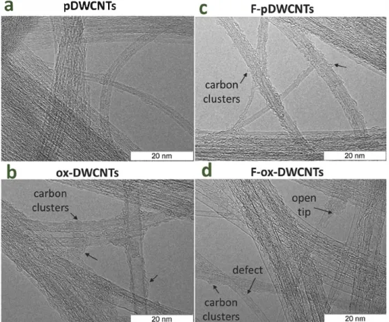
Typical TEM images of air purified DWCNTs (pDWCNTs), acid purified/oxidized DWCNTs (ox DW<NTs) and these samples after fluorination (F pDWCNTs and F ox DWCNTs) are presented in Fig. 1.
The first sample consists of clean DWCNTs with no visible impurities of amorphous carbon by products or carbon encapsulated catalytic me tallic particles (Fig. la), which are commonly formed during the CCVD synthesis and present in the as grown material (38). It means that the purification by oxidation in air removes almost ail the amorphous carbon impurities. TEM analysis of ox DWCNTs highlighted carbon deposits on the nanotube surface (indicated by arrows in Fig. lb). It should be noted that in previous works oxidation of nanotubes, opening of nanotube's tips and formation of defects were discovered after oxi dative treatments with concentrated nitric and sulphuric acids (35,36,40). Such functionalized nanotubes are less stable and can be
a
pDWCNTs
514nm
20
100 200 300 400
1200 1500 1800 2100 2500
3000
Raman shift (cm"1)
Fig. 2. Raman spectra at 514 nm excitation wavelength of pDWCNTs and ox DWCNTs before and after fluorination (F-pDWCNTs and F-ox-DWCNTs). partially broken under the electron beam during the TEM observation with the formation of surface carbon clusters. The tubular structure of the pDWCNTs and ox DWCNTs was preserved after the fluorination (Fig. le, d). However, at the visual inspection, it seems that amounts of sidewall carbon clusters and defects increases, especially in the oxy fluorinated sample denoted F ox DWCNTs (Fig. Id). We assume that
further destructions observed for the fluorinated samples are the result of the electron beam effect, which has been previously observed for highly fluorinated SWCNTs [ 48). Oxyfluorinated DWCNTs appear to be less stable, probably due to a higher concentration of fluorine surface groups.
Fig. 2 compares the Raman spectra of the samples. The spectra are typical for DWCNTs, showing radial breathing modes (RBM) in the region of 100 400cm-1, a sharp tangential mode Gat -1586cm-1, a
Fig. 1. TBM images of air-purified DWCNTs (a, pDWCNTs), oxidized/purified DWCNTs (b, ox-DWCNTs), fluorinated pDWCNTs (c, F-pDWCNTs) and fluorinated ox DWCNTs (d, F-ox-DWCNTs).
states of carbon in the samples were revealed from the analysis of C 1s
spectra, which werefitted by five components (Fig. 3). The spectrum of
pDWCNTs has an asymmetric peak at 284.5 eV, characteristic of sp2
hybridized carbon (Fig. 3a). A weak component Cdat 285.3 eV refers to
disordered carbon and surface defect states[54]. According to low ID/
IGintensity in the Raman spectrum of this sample, the residual amor
phous carbon is likely not aromatic but tetrahedral with a high content
of sp3bonding and/or hydrogen[55]. Moreover, defect states in the
DWCNT walls may be considered as an intermediate between the sp2
and sp3states and can also contribute to the component C
dat 285.3 eV.
The peak at 286.3 eV corresponds to carbon atoms bonded with one
oxygen atom (CeO) in hydroxyl, ether, epoxy, or other oxygen con
taining groups[30,56,57]. The integral intensity of this peak is ca. 3%
of the total spectral intensity. The peak at 288.3 eV arises from carbon
atoms bonded with two oxygen atoms (CeO2) in carboxyl groups lo
cated at edges of vacancy defects and graphene layers[30,56 58]. The
intensity of this peak is three times less than the intensity of the CeO
component. Theπ → π* electron transitions produce a satellite peak at
291.3 eV.
The C 1s XPS spectrum of ox DWCNTs (Fig. 3b) showed the sp2and
Cdcomponents of the shape and intensity similar to those in the spec
trum of pDWCNTs. That means that the used acidic treatment did not lead to noticeable destruction of the DWCNTs. On the other hand, such oxidation treatment caused the covalent functionalization of DWCNTs
as can be seen from an increase in the intensities of the CeO and CeO2
components. The intensity of the former component is three times greater than the latter one. Commonly, treatment with concentrated nitric and sulphuric acids increases the content of carboxylic groups in
the CNT samples[59 61]. Most of these groups are mainly located at
the edges of small carboxylated carbon fragments, which appear as a result of oxidation of carbon graphene like impurities. Almost all these fragments were removed by oxidation of the DWCNT sample in air
before the acidic treatment (Fig. 1a); thus the carboxylic groups de
tected by XPS were most likely located at the open nanotube edges. Analysis of O 1s XPS and NEXAFS O K edge spectra detected the pre
sence of different oxygen containing groups in the samples (Fig. S2 in
Fig. 3. C 1s XPS spectra of pDWCNTs and ox-DWCNTs before and afterfluorination (F-pDWCNTs and DWCNTs) (a, b). F 1s XPS spectra of F-pDWCNT and F-ox-DWCNT (c). Compact and isolated CF areas give eponymous components in the F 1s spectra (c).
disorder induced mode D at 1350 cm−1, and a two phonon 2D band at
2680 cm−1 [49]. The integral ratio of the intensities of D mode to G
mode (ID/IG) in the Raman spectrum of pDWCNTs was equal to 0.02.
This low value indicates that the air purified DWCNTs have a long
range sp2 hybridized carbon order along sidewalls and a small amount
of graphene like carbon contaminations. The frequency positions of the RBM peaks allow us to analyze the distribution of diameters of the DWCNTs, which are excited at 514 nm. According to the relations
ωRBM(cm−1) = 228/d(nm) for the inner tubes, and
ωRBM(cm−1) = 204/d(nm) + 27(cm−1) for the outer tubes, where
ωRBM is the position of RBM peak and d is the diameter of a nanotube
[50], we calculated the corresponding values in ranges of 0.6 1.1 nm
and 1.5 1.8 nm. The spectrum of ox DWCNTs exhibited the D mode
with a slightly higher intensity (ID/IG = 0.1) and RBM peaks with in
tensities less than those for pDWCNTs. These changes indicate that acidic oxidative treatments produce some structural defects or/and functional groups on sidewalls of DWCNTs.
An increase in the intensity of the D peak in the Raman spectra of
the fluorinated samples (ID/IG ratio is 0.3 for F pDWCNTs and 0.4 for F
ox DWCNTs) points out that DWCNTs are chemically functionalized by fluorine. The formation of C F bonds also resulted in a decrease in the intensity of RBM peaks. The strongest spectral changes observed for oxyfluorinated DWCNTs indicate the highest degree of the modifica tion. The 2D peak in the spectrum of pDWCNTs has a broad asymmetric shape due to the averaging series of individual 2D peaks from nano
tubes with different (n,m) configurations [51 53]. The shape of the 2D
peak changed slightly after both oxidation and fluorination of the sample. That phenomenon can be explained by changes in the structure
of the π electron system after the chemical modification. The ratio I2D/
IG was 0.4 for pDWCNTs, ox DWCNTs, and F pDWCNTs and it de
creased to 0.3 for F ox DWCNTs, meaning that the decrease in re sonance from part of the nanotubes was due to the high degree of functionalization.
XPS survey spectra of the samples revealed signals from carbon, oxygen, copper from substrates, and fluorine atoms in the case of
σ* transitions, respectively[49,58]. The features located betweenπ*
and σ* resonances refer to the carbon atoms bound to oxygen and
fluorine[26,27,33,66]. The high intensity and a sharpness of theπ*
andσ* resonances in the spectrum of pDWCNTs indicates a perfect
atomic structure of the nanotubes (Fig. 4a). The spectrum of ox
DWCNTs showed a quite strong feature at 288.8 eV (Fig. 4b) formed by
oxygenated carbon species [58,66]. The spectra of the fluorinated
samples differ from the spectra of parent samples by the features be
tween 287 and 290 eV due to covalent CeF bonding. High relative in
tensity of theπ* resonance and weak intensity of the CeF/CeO fea
tures in the spectrum of F pDWCNTs (Fig. 4a) are due to a low sidewall
fluorination level of the nanotubes. In contrast to this result, the spec trum of F ox DWCNTs exhibited a substantial decrease in the intensity
of π* resonance and an increase in the intensity at 287 290 eV
(Fig. 4b). These spectral changes mean thatfluorine atoms are cova lently attached to the surface of oxidized DWCNTs with broken of the
conjugatedπ electron system.
Previously we showed that NEXAFS F K edge spectra are sensitive to
thefluorine pattern and number, position, and intensity of pre edge
features may vary depending on thefluorination method[26,27]. The F
K edge spectra of thefluorinated DWCNTs exhibited two shoulders A
and B at ca. 689.0 and ca. 686.5 eV in the region before the adsorption
edge C (Fig. 5a). These pre edge features come from fluorine atoms,
which form shortfluorinated chains on the surface of CNTs[26]. De
spite the higher concentration offluorine in the oxyfluorinated sample,
features A and B have lower intensities than those in the spectrum of
thefluorinated sample (Fig. 5a).
To reveal the influence of basal and edge oxygen containing groups
on the electronic state offluorine, we performed the DFT calculations of
the models presented inFig. 5b. We used a fragment of (12,12) tube as a
model of the non modified surface of pDWCNTs. Since the used fluor
ination method produces short CF chains [24,26,27], four F atoms
forming a zigzag chain in the central convex part of the tube fragment
were used for modeling of afluorinated tube (model 1). The acidic
oxidation of DWCNTs can produce only hydroxyl groups covalently grafted to sidewalls. A hydroxyl group replaced one edge F atom in the fluorinated model 1 to get the model 2 of oxyfluorinated DWCNTs. The edges of defects and open DWCNT tips, appeared during the oxidation,
can be modified by eCOOH and CeOeC groups. According to the XPS
data, the concentration of eCOOH groups was very low in the ox
DWCNTs sample, and therefore, we did not consider thefluorinated
models with these groups. Moreover, ether groups located at the edges
Fig. 4. NEXAFS C K-edge spectra of pDWCNTs (a) and ox-DWCNTs (b) before and afterfluorination (F-pDWCNTs and F-ox-DWCNTs).
Supporting Information). These spectra confirm that the CeO bonding prevails in the ox DWCNTs.
Two peaks at 288.4 and 290.6 eV were distinguished in C 1s XPS
spectra of fluorinated samples (Fig. 3a,b). The peak at 288.4 eV corre
sponds to carbon atoms covalently bonded with one fluorine atom
(CeF), which is located on the outer surface of CNTs [13,26,30]. The
peak at 290.6 eV arises from carbon atoms covalently bonded to two
fluorine atoms (CeF2). These groups are more probably located at open
nanotube tips. Carbon atoms linked with CF groups (CeCF) give a contribution to the component at 285.5 eV. For F pDWCNTs, areas of
the CeF and CeF2 peaks were 5% and 4%, respectively. In the spectrum
of F ox DWCNTs, the CeF2 peak was absent, and the area of the CeF
peak was 11%. The fitting of the C 1s spectra gives compositions (CF0.05)0.96(CF2)0.04 for sample F pDWCNT and CF0.11 for sample F ox
DWCNTs. The more significant number of CF2 groups in pDWCNTs was
likely formed at the DWCNT ends opened after annealing in air. In the F ox DWCNTs, these sites were probably initially occupied by oxygen containing groups during the treatment by acids. However, the con centration of sidewall fluorine atoms in F ox DWCNTs was two times higher than that in F pDWCNTs.
The chemical state of fluorine was identified from the analysis of F
1s lines, which were fitted by three components. Fig. 3c compares the F
1s XPS spectra for F pDWCNTs and F ox DWCNTs. The binding energy of F 1s levels of the fluorinated CNTs was lower than that for graphite
fluorides CF and C2F [62]. The F 1s peak shifted toward higher binding
energy with fluorine loading as experimentally shown [50]. We tenta
tively approximated the F 1s spectra by three components at 688.4, 686.9, and 684.7 eV, which all belong to the covalent CeF bonds. The component at low energy of 684.7 eV indicates a weakly bonded F
atoms [24]. According to quantum chemical calculations, the weak
ening of CeF bonding is observed when a fluorine atom locates far from other fluorinated carbon atoms and is caused by overlapping of elec trons of the F atom with the π system of bare carbon regions
[26,63,64]. The high energy F 1s component at 688.4 eV, on the con
trary, can be assigned to the F atoms strongly interacting with carbon in
the highly fluorinated CF areas and the edge CF2 groups [26,50,65]. An
intense intermediate peak at 686.9 eV refers to all other fluorine pat terns. Comparison of the spectra indicates that F pDWCNTs contain a larger number of the isolated CF groups and F ox DWCNTs are enriched with compact CF areas.
NEXAFS C K edge spectra of the samples had two main resonances
of graphene planes were shown to be the most stable underfluorination
[18]. We placed an O atom bonded to twofluorinated C atoms at the
edge of a double atomic vacancy in model 3.
Fig. 5a shows the theoretical F K spectra plotted for all fluorine atoms in models 1 3 using (Z+1) approximation. The spectrum of the fluorinated model 1 has three peaks, which coincide in related intensity and energy with the features A C in the experimental spectrum. The
spectra of the two oxyfluorinated models 2 and 3 show a strong de
crease in the intensity of peak A as well as a small decrease of peak B. These spectral changes correlate with the experimental ones observed
for F pDWCNTs and F ox DWCNTs. Since carbon pzorbital is required
for sidewallfluorine attachment and the perfect π system is not easily
destroyed, the reaction may start from the C atoms located near oxy genated carbon atoms. The attachment of oxygen weakens the neigh
boring C]C bonds, thus improving their reactivity to fluorine. We
suggest that in our oxyfluorinated sample, the CF areas are compact and located near the carbon atoms bonded with oxygen groups.
Previously, the investigation of reactivity of graphene oxides to
fluorination by F2gas at elevated temperatures revealed that oxygen
groups promote fluorination reaction and formation of covalent CeF
bonds [18]. Moreover, Chen and colleagues[18]found that the con
centration of oxygen containing groups decreased during the high
temperaturefluorination and concluded that F radicals replaced car
bonyl and hydroxyl groups and only ether groups resisted the high
temperature and the attack offluorine radicals. In our case, the con
centration of sidewall oxygen in the ox DWCNTs was not so high, and F atoms were rather attached to the non functionalized C atoms than
replacing oxygen containing groups. The same way that fluorine gas
initiates the reaction of MWCNTs with oxygen during one step oxy
fluorination[3], oxidized carbon atoms, already presented on the sur
faces and edges of DWCNTs, become reactive sites for thefluorination
of neighboring carbon areas. 4. Conclusion
DWCNTs, purified by heating in air (sample pDWCNTs) and the
oxidative acidic media (sample ox DWCNTs), were compared under
fluorination by gaseous BrF3 at room temperature. TEM, Raman
scattering, XPS, and NEXAFS measurements examined the composition
and atomic structure of the initial andfluorinated samples. The use of
purified DWCNTs is important to make sure that the fluorination oc curred only on a CNT and not on other carbon species, such as amor phous carbon. The analysis of the XPS data found ca. 2 at% of oxygen in the pDWCNTs mainly in carboxylic groups and ca. 12 at% of oxygen in the ox DWCNTs mostly in the sidewall groups. Fluorination of the
former sample yielded 5 at% offluorine covalently bonded with carbon
(C F) and 8 at% of fluorine in the edge CF2 groups. Only sidewall
fluorination (ca. 11 at%) was detected for the fluorinated ox DWCNTs. A comparison of experimental NEXAFS F K edge spectra with the spectra plotted using the DFT calculations of models revealed that fluorine is preferentially attached near the oxygen containing groups on the nanotube surface. Even a small number of oxygen containing groups covalently bonded to DWCNTs promotes the formation of many fluorinated areas, which cumulate near oxidized carbon. This ob servation may explain the difference observed and reported in the
concentration of fluorine in the fluorinated CNTs and other carbon
materials, which are obtained under the samefluorination conditions.
The presence of a small concentration of oxygen should be taken into
account in the further chemical modification of CNTs and other carbon
materials.
Declaration of Competing Interest
The authors declare that they have no known competingfinancial
interests or personal relationships that could have appeared to influ
ence the work reported in this paper.
Acknowledgements
We are grateful to Mr. A.V. Ishchenko for the TEM measurements. The work has been supported by the Russian Foundation for Basic
Research (Grant № 16 53 150003) and PRC CNRS/RFBR (Grant №
1023) and the bilateral Program “Russian German Laboratory at
BESSY” in the part of XPS and NEXAFS measurements.
Fig. 5. Experimental NEXAFS F K-edge spectra of F-pDWCNTs and F-ox-DWCNTs in comparison with calculated spectra (1–3) constructed for fluorine atoms in the models 1–3 (a). Fragment of the tube (12, 12), and the fragments of the tube with fluorinated (model 1) and oxyfluorinated (models 2 and 3) central convex part (b).
[1] M. Monthioux, E. Flahaut, C. Laurent, W. Escoffier, B. Raquet, W. Bacsa, et al., Properties of carbon nanotubes, in: B. Bhushan, D. Luo, S.R. Schricker, W. Sigmund, S. Zauscher (Eds.), Handbook of Nanomaterials Properties, Springer Materials, Berlin, 2014, pp. 1–49.
[2] T. Hayashi, D. Shimamoto, Y.A. Kim, H. Muramatsu, F. Okino, H. Touhara, et al., Selective optical property modification of double-walled carbon nanotubes by fluorination, ACS Nano 2 (3) (2008) 485–488.
[3] Y. Liu, X. Wang, W. Wang, B. Li, P. Wu, M. Ren, et al., One-step preparation of oxygen/fluorine dual functional MWCNTs with good water dispersibility by the initiation offluorine gas, ACS Appl. Mater. Interfaces 8 (2016) 7991–7999. [4] K.M. Lee, S.-E. Lee, Y.-S. Lee, Improved mechanical and electromagnetic
inter-ference shielding properties of epoxy composites through the introduction of oxy-fluorinated multiwalled carbon nanotubes, J. Ind. Eng. Chem. 56 (2017) 435–442. [5] J. Yun, J.S. Im, Y.-S. Lee, H.-I. Kim, Effect of oxyfluorination on electromagnetic
interference shielding behavior of MWCNT/PVA/PAAc composite microcapsules, Eur. Polym. J. 46 (2010) 900–909.
[6] J. Yun, J.S. Im, H.-I. Kim, Y.-S. Lee, Effect of oxyfluorination on gas sensing be-havior of polyaniline-coated multi-walled carbon nanotubes, Appl. Surf. Sci. 258 (2012) 3462–3468.
[7] H.-R. Yu, J.G. Kim, J.S. Im, T.-S. Bae, Y.-S. Lee, Effects of oxyfluorination on a multi-walled carbon nanotube electrode for a high-performance glucose sensor, J. Ind. Eng. Chem. 18 (2012) 674–679.
[8] M.-J. Jung, E. Jeong, J.W. Lim, S.I. Lee, Y.-S. Lee, Physico-chemical surface mod-ification of activated carbon by oxyfluorination and its electrochemical character-ization, Colloids Surf. A: Physicochem. Eng. Asp. 389 (2011) 274–280. [9] Y.-S. Lee, Syntheses and properties offluorinated carbon materials, J. Fluor. Chem.
128 (2007) 392–403.
[10] S.D. Kim, J.W. Kim, J.S. Im, Y.H. Kim, Y.S. Lee, A comparative study on properties of multi-walled carbon nanotubes (MWCNTs) modified with acids and oxyfluor-ination, J. Fluor. Chem. 128 (2007) 60–64.
[11] S.-J. Park, H.-J. Jeong, C. Nah, A study of oxyfluorination of multi-walled carbon nanotubes on mechanical interfacial properties of epoxy matrix nanocomposites, Mat. Sci. Eng. A 385 (2004) 13–16.
[12] M.-K. Seo, S.-J. Park, Surface characteristics of carbonfibers modified by direct oxyfluorination, J. Colloid Interf. Sci. 330 (2009) 237–242.
[13] C. Struzzi, M. Scardamaglia, A. Hemberg, L. Petaccia, J.-F. Colomer, R. Snyders, et al., Plasmafluorination of vertically aligned carbon nanotubes: functionalization and thermal stability, Beilstein J. Nanotechnol. 6 (2015) 2263–2271.
[14] F. Chamssedine, D. Claves, Selective substitution offluorine atoms grafted to the surface of carbon nanotubes and application to an oxyfluorination strategy, Carbon 46 (2008) 957–962.
[15] M.X. Pulikkathara, O.V. Kuznetsov, V.N. Khabashesku, Sidewall covalent functio-nalization of single wall carbon nanotubes through reactions offluoronanotubes with urea, guanidine, and thiourea, Chem. Mater. 20 (2008) 2685–2695. [16] X. Wang, Y. Chen, Y. Dai, Q. Wang, J. Gao, J. Huang, et al., Preparing highly
fluorinated multiwall carbon nanotube by direct heating-fluorination during the elimination of oxygen-related groups, J. Phys. Chem. C 117 (2013) 12078–12085. [17] M.-S. Park, Y.-S. Lee, Functionalization of graphene oxide byfluorination and its
characteristics, J. Fluor. Chem. 182 (2016) 91–97.
[18] T. Chen, X. Wang, Y. Liu, B. Li, Z. Cheng, Z. Wang, et al., Effects of the oxygenic groups on the mechanism offluorination of graphene oxide and its structure, Phys. Chem. Chem. Phys. 19 (2017) 5504–5512.
[19] M.-S. Park, K.H. Kim, M.-J. Kim, Y.-S. Lee, NH3gas sensing properties of a gas
sensor based onfluorinated graphene oxide, Colloids Surf. A: Physicochem. Eng. Asp. 490 (2016) 104–109.
[20] V.I. Sysoev, A.V. Okotrub, I.P. Asanov, P.N. Gevko, L.G. Bulusheva, Advantage of graphenefluorination instead of oxygenation for restorable adsorption of gaseous ammonia and nitrogen dioxide, Carbon 118 (2017) 225–232.
[21] O. Jankovský, P.Šimek, D. Sedmidubský, S. Matějková, Z. Janoušek, F. Šembera, et al., Water-soluble highlyfluorinated graphite oxide, RSC Adv. 4 (2014) 1378–1387.
[22] M. Mar, M. Dubois, K. Guérin, N. Batisse, B. Simon, P. Bernard, Tuningfluorine and oxygen distribution in graphite oxifluorides for enhanced performances in primary lithium battery, Carbon 141 (2019) 6–15.
[23] A. Vyalikh, L.G. Bulusheva, G.N. Chekhova, D.V. Pinakov, A.V. Okotrub, U. Scheler, Fluorine patterning in room-temperaturefluorinated graphite determined by solid-state NMR and DFT, J. Phys. Chem. C 117 (2013) 7940–7948.
[24] I.P. Asanov, L.G. Bulusheva, M. Dubois, N.F. Yudanov, A.V. Alexeev, T.L. Makarova, et al., Graphene nanochains and nanoislands in the layers of room-temperature fluorinated graphite, Carbon 59 (2013) 518–519.
[25] Yu.V. Lavskaya, L.G. Bulusheva, A.V. Okotrub, N.F. Yudanov, D.V. Vyalikh, A. Fonseca, Comparative study offluorinated single- and few-wall carbon nano-tubes by X-ray photoelectron and X-ray absorption spectroscopy, Carbon 47 (2009) 1629–1636.
[26] L.G. Bulusheva, Y.V. Fedoseeva, E. Flahaut, J. Rio, C.P. Ewels, V.O. Koroteev, et al., Effect of the fluorination technique on the surface-fluorination patterning of double-walled carbon nanotubes, Beilstein J. Nanotechnol. 8 (2017) 1688–1698.
[27] L.G. Bulusheva, Yu.V. Fedoseeva, A.V. Okotrub, E. Flahaut, I.P. Asanov, V.O. Koroteev, et al., Stability offluorinated double-walled carbon nanotubes produced by different fluorination techniques», Chem. Mater. 22 (2010) 4197–4203.
[28] C. Struzzi, M. Scardamaglia, N. Reckinger, H. Sezen, M. Amati, L. Gregoratti, et al., Probing plasmafluorinated graphene via spectromicroscopy, Phys. Chem. Chem. Phys. 19 (2017) 31418–31428.
[29] Yu.V. Fedoseeva, L.G. Bulusheva, A.V. Okotrub, D.V. Vyalikh, A. Fonseca, High reactivity of carbon nanotubes andfluorinated carbon nanotubes irradiated by Ar+
ions, Phys. Status Solidi B 247 (2010) 2691–2694.
[30] Yu.V. Fedoseeva, L.G. Bulusheva, A.V. Okotrub, D.V. Vyalikh, A. Fonseca, A com-parative study of argon ion irradiated pristine andfluorinated single-wall carbon nanotubes, J. Chem. Phys. 133 (2010) 224706.
[31] K.A. Wepasnick, B.A. Smith, K.E. Schrote, H.K. Wilson, S.R. Diegelmann, D. Howard Fairbrother, Surface and structural characterization of multi-walled carbon nano-tubes following different oxidative treatments, Carbon 49 (2011) 24–26. [32] I. Suarez-Martinez, C. Bittencourt, X. Ke, A. Felten, J.J. Pireaux, J. Ghijsen, et al.,
Probing the interaction between gold nanoparticles and oxygen functionalized carbon nanotubes, Carbon 47 (2009) 1549–1554.
[33] A.V. Okotrub, N.F. Yudanov, I.P. Asanov, D.V. Vyalikh, L.G. Bulusheva, Anisotropy of chemical bonding in semifluorinated graphite C2F revealed with angle-resolved
X-ray absorption spectroscopy, ACS Nano 22 (2013) 65–74.
[34] Z. Qian, J. Ma, J. Zhou, P. Lin, C. Chen, J. Chen, et al., Facile synthesis of halo-genated multi-walled carbon nanotubes and their unusual photoluminescence, J. Mater. Chem. 22 (2012) 22113–22119.
[35] Z. Qian, J. Zhou, J. Ma, X. Shan, C. Chen, J. Chen, et al., The visible photo-luminescence mechanism of oxidized multi-walled carbon nanotubes: an experi-mental and theoretical investigation, J. Mater. Chem. C 1 (2013) 307–314. [36] L. Minati, G. Speranza, I. Bernagozzi, S. Torrengo, L. Toniutti, B. Rossi, et al.,
Investigation on the electronic and optical properties of short oxidized multiwalled carbon nanotubes, J. Phys. Chem. C 114 (2010) 11068–11073.
[37] E. Flahaut, R. Bacsa, A. Peigney, Ch. Laurent, Gram-scale CCVD synthesis of double-walled carbon nanotubes, Chem. Commun. 12 (2003) 1442–1443.
[38] S. Osswald, E. Flahaut, Y. Gogotsi, In situ Raman spectroscopy study of oxidation of double- and single-wall carbon nanotubes, Chem. Mater. 18 (2006) 1525–1533. [39] E.V. Lobiak, L.G. Bulusheva, E.O. Fedorovskaya, Y.V. Shubin, P.E. Plyusnin,
P. Lonchambon, et al., One–step chemical vapor deposition synthesis and super-capacitor performance of nitrogen–doped porous carbon–carbon nanotube hybrids, Beilstein J. Nanotechnol. 8 (2017) 2669–2679.
[40] T. Bortolamiol, P. Lukanov, A.-M. Galibert, B. Soula, P. Lonchambon, L. Datas, et al., Double-walled carbon nanotubes: Quantitative purification assessment, bal-ance between purification and degradation and solution filling as an evidence of opening, Carbon 78 (2014) 79–90.
[41] N.F. Yudanov, A.V. Okotrub, YuV. Shubin, L.I. Yudanova, L.G. Bulusheva, A.L. Chuvilin, et al., Fluorination of arc-produced carbon material containing multiwall nanotubes, Chem. Mater. 14 (2002) 1472–1476.
[42] A.D. Becke, Density-functional thermochemistry. III. The role of exact exchange, J. Chem. Phys. 98 (1993) 5648–5652.
[43] C. Lee, W. Yang, R.G. Parr, Development of the Colle-Salvetti correlation-energy formula into a functional of the electron density, Phys. Rev. B 37 (1988) 785–789. [44] Jaguar, Version 9.2, Schrödinger, LLC, New York, NY, U.S.A., 2016.
[45] W.H.E. Schwarz, Interpretation of the core electron excitation spectra of hydride molecules and the properties of hydride radicals, Chem. Phys. 11 (1975) 217–228. [46] Yu.V. Fedoseeva, L.G. Bulusheva, A.V. Okotrub, I.P. Asanov, S.I. Troyanov,
D.V. Vyalikh, Electronic structure of the chlorinated fullerene C60Cl30studied by
quantum-chemical modeling of X-ray absorption spectra, Int. J. Quantum Chem. 111 (2011) 2688–2695.
[47] L.G. Bulusheva, A.V. Okotrub, Yu.V. Lavskaya, D.V. Vyalikh, U. Dettlaff-Weglikowska, A. Fonseca, et al., Comparative NEXAFS examination of single-wall carbon nanotubes produced by different methods, Phys. Status Solidi B 246 (2009) 2637–2640.
[48] Y.S. Lee, T.H. Cho, B.K. Lee, J.S. Rho, K.H. An, Y.H. Lee, Surface properties of fluorinated single-walled carbon nanotubes, J. Fluor. Chem. 120 (2003) 99–104. [49] M.S. Dresselhaus, G. Dresselhaus, A. Jorio, A.G. Souza Filho, R. Saito, Raman
spectroscopy on isolated single wall carbon nanotubes, Carbon 40 (2002) 2043–2061.
[50] D. Levshov, T.X. Than, R. Arenal, V.N. Popov, R. Parret, M. Paillet, et al., Experimental evidence of a mechanical coupling between layers in an individual double-walled carbon nanotube, Nano Lett. 11 (2011) 4800–4808.
[51] L.G. Moura, M.V.O. Moutinho, P. Venezuela, F. Mauri, A. Righi, M.S. Strano, et al., The double-resonance Raman spectra in single-chirality (n, m) carbon nanotubes, Carbon 117 (2017) 41–45.
[52] P. Puech, E. Flahaut, A. Bassil, T. Juffmann, F. Beuneu, W.S. Bacsa, Raman bands of double-wall carbon nanotubes: comparison with single- and triple-wall carbon na-notubes, and influence of annealing and electron irradiation, J. Raman Spectrosc. 38 (2007) 714–720.
[53] Y. Stubrov, A. Nikolenko, V. Gubanov, V. Strelchuk, Manifestation of structure of electron bands in double-resonant Raman Spectra of single-walled carbon nano-tubes, Nanoscale Res. Lett. 11 (2016) 2.
[54] R. Blume, D. Rosenthal, J.P. Tessonnier, H. Li, A. Knop-Gericke, R. Schlçgl, Characterizing graphitic carbon with X-ray photoelectron spectroscopy: a step-by-step approach, Chem. Cat. Chem. 7 (2015) 2871–2881.
[55] P.K. Chu, L. Li, Characterization of amorphous and nanocrystalline carbonfilms, Mat. Chem. Phys. 96 (2006) 253–277.
[56] Yu.V. Fedoseeva, G.A. Pozdnyakov, A.V. Okotrub, M.A. Kanygin, Yu.V. Nastaushev, O.Y. Vilkov, et al., Effect of substrate temperature on the structure of amorphous
Appendix A. Supplementary material
Supplementary data to this article can be found online at https://
doi.org/10.1016/j.apsusc.2019.144357. References
oxygenated hydrocarbonfilms grown with a pulsed supersonic methane plasma flow, Appl. Surf. Sci. 385 (2016) 464–471.
[57] M. Krysak, B. Parekh, T. Debies, R.A. Dileo, B.J. Landi, R.P. Raffaelle, et al., Gas-phase surface functionalization of multiwalled carbon nanotubes with vacuum UV photooxidation, J. Adhes. Sci. Technol. 21 (2012) 999–1007.
[58] J. Zhang, H. Zou, Q. Qing, Y. Yang, Q. Li, Z. Liu, et al., Effect of chemical oxidation on the structure of single-walled carbon nanotubes, J. Phys. Chem. B 107 (2003) 3712–3718.
[59] O.A. Gurova, V.E. Arhipov, V.O. Koroteev, T.Y. Guselnikova, I.P. Asanov, O.V. Sedelnikova, et al., Purification of single-walled carbon nanotubes using acid treatment and magnetic separation, Phys. Status Solidi B (2019) 1800742. [60] K.A. Worsley, I. Kalinina, E. Bekyarova, R.C. Haddon, functionalization and
dis-solution of nitric acid treated single-walled carbon nanotubes, J. Am. Chem. Soc. 131 (2009) 18153–18158.
[61] L. Shao, G. Tobias, C.G. Salzmann, B. Ballesteros, S.Y. Hong, A. Crossley, et al., Removal of amorphous carbon for the efficient sidewall functionalisation of
single-walled carbon nanotubes, Chem. Commun. (2007) 5090–5092.
[62] H. Touhara, J. Inahara, T. Mizuno, Y. Yokoyama, S. Okanao, K. Yanagiuch, et al., Property control of new forms of carbon materials byfluorination, J. Fluor. Chem. 114 (2000) 181–188.
[63] Y. Sato, K. Itoh, R. Hagiwara, T. Fukunaga, Y. Ito, On the so-called‘‘semi-ionic’’ C-F bond character influorine–GIC, Carbon 42 (2004) 3243–3249.
[64] P. Wang, H. Wang, W. Yang, Anomalous high adsorption energy of H2O on
fluorinated graphenes: A first principles study, Phys. Chem. Chem. Phys. 16 (2014) 20464–20470.
[65] Y.V. Fedoseeva, A.V. Okotrub, I.P. Asanov, D.V. Pinakov, G.N. Chekhova, V.A. Tur, et al., Nitrogen inserting influorinated graphene via annealing of acetonitrile in-tercalated graphitefluoride, Phys. Status Solidi B 251 (2014) 2530–2535. [66] A. Kuznetsova, I. Popova, J.T. Yates, M.J. Bronikowski Jr, C.B. Huffman, J. Liu,
et al., Oxygen-containing functional groups on single-wall carbon nanotubes: NEXAFS and vibrational spectroscopic studies, J. Am. Chem. Soc. 123 (2001) 10699–10704.
Supporting information
Preferred attachment of fluorine near oxygen-containing
groups on the surface of double-walled carbon nanotubes
Yu. V. Fedoseeva
1,2, L. G. Bulusheva
1,2, V.O. Koroteev
1,2, J.-Y. Mevellec
3, B.V. Senkovskiy
4,5,
E. Flahaut
6, A. V. Okotrub
1,21
Nikolaev Institute of Inorganic Chemistry SB RAS, 3 Acad. Lavrentiev Ave., 630090
Novosibirsk, Russia
2
Novosibirsk State University, 2 Pirogova Str., 630090 Novosibirsk, Russia
3
Institut des Matériaux Jean-Rouxel (IMN), CNRS–UMR 6502, Université de Nantes,
2 rue de la
Houssinière, BP 32229, 44322 Nantes Cedex 3, France
4
St. Petersburg State University, 7-9, Universitetskaya Nab., St. Petersburg 199034, Russia
5II Physikalisches Institut, Universität zu Köln, Zülpicher Straße 77, 50937 Köln, Germany
6
CIRIMAT, Université de Toulouse, CNRS, INPT, UPS, UMR CNRS-UPS-INP N°5085,
Université Toulouse 3 Paul Sabatier, Bât. CIRIMAT, 118, route de Narbonne, 31062 Toulouse
cedex 9, France
700
600
500
400
300
200
100
0
700
600
500
400
300
200
100
0
O 1s
93 at%
Binding energy (eV)
7 at% 3 at% 97 at%Cu 3p
C 1s
F 1s
In
te
ns
ity
F-ox-DWCNT
F-pDWCNT
830 eV
538 536 534 532 530 528 C-O C=O 528 532 536 540 544 XPS O 1s C=O(OH)
pDWCNTs
C-O C=O(OH)ox-DWCNTs
NEXAFS O K-edgeox-DWCNTs
pDWCNTs
538
536
534
532
530
528
b
Photon energy (eV)
Binding energy (eV)
a
528
532
536
540
544
C=O