Official URL
DOI : https://doi.org/10.1007/978-3-030-00856-7_13
Any correspondence concerning this service should be sent
to the repository administrator: [email protected]
This is an author’s version published in:
http://oatao.univ-toulouse.fr/24829 Open Archive Toulouse Archive Ouverte
OATAO is an open access repository that collects the work of Toulouse researchers and makes it freely available over the web where possible
To cite this version: Rouland, Quentin and Hamid, Brahim and
Jaskolka, Jason Formalizing Reusable Communication Models for
Distributed Systems Architecture. (2018) In: 8th International Conference
On Model and Data Engineering (MEDI 2018), 24 October 2018 - 26 October 2018 (Marrakesh, Morocco).
Formalizing Reusable Communication
Models for Distributed Systems
Architecture
Quentin Rouland1, Brahim Hamid1(B), and Jason Jaskolka2 1 IRIT, University of Toulouse, Toulouse, France
{quentin.rouland,brahim.hamid}@irit.fr
2 Systems and Computer Engineering Carleton University Ottawa, Ontario, Canada
Abstract. Building distributed computing systems involves complex concerns integrating a multitude of communication styles, technologies (IoT, cloud and big data...), stakeholders (architects, developers, inte-grators, etc.) and addressing a multitude of application domains (smart cities, health, mobility, etc.). Existing architectural description languages fail to rigorously bridge the gap between the abstract representation of communication styles and those supported by existing execution infras-tructures. In this paper, we aim at specifying software architecture of dis-tributed systems using an approach combining semi-formal and formal languages to build reusable model libraries to represent communication solutions. Our contribution is two fold. First, we propose a metamodel to describe high level concepts of architecture in a component- port-connector fashion focusing on communication styles. Second, we attempt to formalize those concepts and their semantics following some proper-ties (specifications) to check architectural conformance. To validate our work, we provide a set of reusable connector libraries within a set of properties to define architectures for systems with explicit communica-tions models like message passing and remote procedure calls, that are common to most distributed systems.
Keywords: Component
·
Connector·
Communication·
Reuse Meta-modeling·
Formalization_
1
Introduction
The shift from traditional computer systems towards the Internet of Things, i.e. devices connected via the Internet, Machine-to-Machine communication (M2M), wireless communication or other interfaces requires a reconsideration of complex software-dependent and distributed systems engineering processes. In fact, this reconsideration introduces new types and levels of risks, including those inher-ited from the underlying technologies like communication, virtualization and containerization. This is especially true for industrial systems, as they exist in many use cases, and systems using web applications with the recent growth of
more applications in cloud-based computing systems. Many of these systems belong to critical infrastructure, on which other economic and social aspects are based on. The foundation for comprehensive rigorous systems engineering facing strong non-functional requirements such as security [21,26], is a compre-hensive understanding of modern communication systems and technologies and their implications on the underlying critical infrastructure [3]. We took this need towards software engineering for distributed software systems, focusing on the problem of integrating communication styles at the level of architecture design to foster reuse. We employ Model-Driven Engineering (MDE) [25] and attempt to add more formality to improve parts of the system design.
When we study distributed systems, we often use models to denote some abstract representation of a distributed system. To encode distributed comput-ing (programs) in such systems, we use a common means of communication [3], where system components have only local vision of the system and inter-act only with their neighbors with explicit communications models like mes-sage passing, remote procedure calls and distributed shared memory, common to most distributed systems. The program executed at each node consists of a set of variables (state) and a finite set of actions. A component can write to its own variables and interact with its neighbors following a specific communica-tion style. In our context, we model software architectures with message passing and remote-procedure call styles that we expect the architectural description to adhere to. The aim of this modeling and verification is to check if the architec-ture models satisfy all the desired properties such as security properties and do not hold any undesired property such as deadlock property.
In this paper, we present a formal framework to support the rigorous design of software architectures focusing on the communication aspects at the architecture level. It is based on the definition of a metamodel to describe high level concepts of architecture in a component- port- connector fashion focusing on communica-tion styles and a formal definicommunica-tion of those concepts and their semantics following some properties (specifications). The former offers a transparent structural def-inition of communication styles (mainly message passing and remote procedure call mechanisms). The latter supports the application designer in the rigorous development process to model and analyze architectural communication styles. In the scope of this paper, we propose to use Alloy [10] for formalizing those com-munication styles and verifying conformance of the comcom-munication style at the model level. The formal specification and verification of a software architecture is represented through an Alloy module based on a set of reusable models, namely connectors corresponding to each of the considered communication styles. We provide a set of reusable connector libraries within a set of properties to define architectures for systems with explicit communications model such as message passing and remote procedure calls.
The remainder of the paper is organized as follows. Section2 compares our work with related work. Section3 presents our component based architectural metamodel. Section4describes the communication style semantics through finite state machine models. Then, Sect.5 presents our approach for supporting the
formalization and verification of these communication models using Alloy. Section6 provides a motivating example that models a software architecture for a web application. Finally, Sect.7 concludes and sketches directions for future work.
2
Related Work
Recent times have seen a paradigm shift in terms of software architecture design [22] by combining multiple software engineering paradigms, namely, Component-Based Development [4], Model-Driven Engineering(MDE) [25] and formal meth-ods [23]. In the spirit of using multi-paradigms, many description languages and formalisms for modeling complex distributed systems have been proposed in the literature. A significant proportion of these works have aimed to capture the communication, concurrency, and some non-functional properties of the compo-nents that make up a given system. Examples of these existing works include those using process algebras (e.g., CSP [9]), architectural modeling languages (e.g., CCM [13], AADL [24], MARTE [16], SysML [14], and the recent OMG initiative UCM [18]), architectural formal languages (e.g., OCL [15], Wright [2], labeled transition systems [20]).
While each of the above mentioned modeling formalisms and modeling lan-guages have already been successful in many application domains, in this paper we build a new communication-based architectural formal modeling language using Alloy for the structural and behavioral specification and analysis of dis-tributed systems. Closely related to this vision is the approach of Khosrav et al. [11] which provides a modeling and analysis of the Reo connectors using Alloy and the approach of Garlan [5] that describes a formal modeling and analysis of software architectures built in terms of the concepts of components, connectors and events. Alloy is a lightweight modeling language, based on first-order rela-tional logic. It provides support for reuse through a separation between the defi-nition of connectors as modules from the description of the software architecture using them. The Alloy formal language is supported by an efficient tool called Alloy Analyzer [1] that will serve as the analysis tool in our experimentations. We provide support for specifying systems at various levels of abstraction by combining the characteristics of both state-based and trace-based models, offer-ing a flexible and verifiable view of communication where several non-functional requirements could be specified and treated in a fine-grained fashion. In contrast to our work, other modeling and formal languages for capturing the communi-cation and non-functional requirements of complex distributed systems do not directly provide such a simple and understandable view.
3
Software Architecture Metamodel
In the context of reliable distributed systems, a connection between distributed components should perform a reliable and trusted communication. While this could be done with standard specification of distributed component-based appli-cations, such as those based on CCM [13,15] and ADL-like [2,24], it would be
impossible to configure and control the reliability and trustworthiness of commu-nication connections at design time. This motivates the usage of the connector concept to embed specific interaction semantics and multiple implementations of the semantics within distributed computing systems. The basic idea of this extension is that the semantics of an interaction is defined by a certain port type and that one or more connectors can support this port type. The port types are already fixed at component design time, whereas the choice of a connector (and a specific communication style) is also constrained by the deployment charac-teristics.
A connector has certain similarities with a component. The main difference is that it is dedicated for communication purposes. Since a connector is respon-sible for incoming, outgoing, intercepting, and blocking data and messages, it is an ideal place for the integration of security and dependability mechanisms. However, connectors are still non-standard interaction mechanisms. For instance there is no corresponding concept in the architecture description languages used in industrial contexts, i.e., containing an UML-like [17] vocabulary.
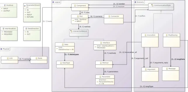
Fig. 1.Component-port-connector metamodel
We propose to build a modeling framework to define architectural models that are conceptually close to the industrial practice, i.e., containing an UML-like and an UCM-UML-like vocabulary. Figure1 visualizes a metamodel as a class diagram. The metamodel provides concepts for describing software architectures in terms of different views [12], with a focus on:
1. Logical view to capture the functional architecture of the system in terms of components.
2. Physical view to describe the deployment of the software onto the hardware taking into account the distributed aspects.
3. Scenario view which builds upon the logical and the physical views, describing the behavioral aspects of the system.
4
Modeling
In order to verify any communication style formally, it is mandatory to model that style carefully. Therefore, in modeling each communication style, each of the two communication parties (client and server) and the channel (connector connecting two ports) between them are described as a finite state machine. 4.1 Message Passing
In the message passing communication style (MPS), a channel is used for sending a message from a client to a server. The message is simply transmitted without any acknowledgement. The communication channel is modeled as a set of fixed length for messages offering two operations: (a) push to add an element in the set and (b) pull to remove an element from the set.
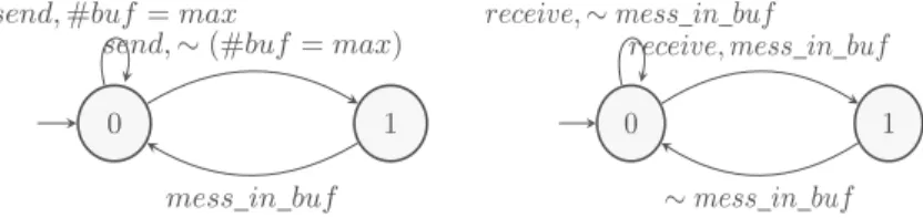
The left side of Fig.2 shows the states of a client for sending a message. It is shown that if the state is sent (0) and a send event occurs when the buffer is not full (∼ (#buf = max)), it changes its state from 0 to 1 for sending 1. On
the other hand, if the buffer is full (#buf = max), it remains at state 0. It also shows that if the state is sending and the message is in the buffer (mess in buf ), it changes its states from 1 to 0 for sent.
Similarly, the right side of Fig.2 shows the states of a server for receiving a message. It is shown that if the state is received (0) and the buffer has a message (mess in buf ), it changes its state from 0 (received) to 1 for receiving a message. On the other hand, if the message is not in the buffer, it remains at state 0. It also shows that if the state is receiving and the message is no longer anymore in the buffer, it changes its states from 1 to 0 for received.
Fig. 2. States of a client (resp. server) for sending (resp. receiving) messages
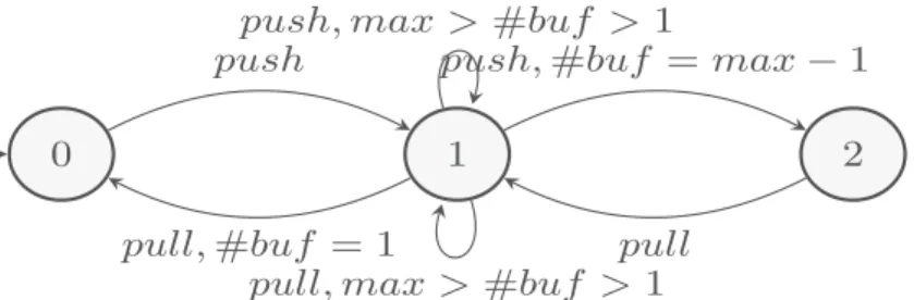
Figure3 shows the states of a connector for pulling and pushing a message. It is shown that if the state is 0 for waiting to receive messages from a caller and a message is pushed into the buffer, it changes its state from 0 to 1. If the current state 1 for waiting to receive message from a caller or retrieving a message from a receiver, it shows that if an event push or pull is executed and the buffer has more than one message but is not full (max > #buf > 1), then it stays in the state 1. Otherwise, if a pull occurs and the buffer only has one message (#buf = 1), it changes its states from 1 to 0. But if a push occurs and the buffer is full minus 1 message (#buf = max − 1), it changes its state from 1 ∼ Q denotes the negation of the statement Q and #A denotes the cardinality of the
1 to 2 for retrieving messages from a receiver. Finally, it shows that to change from state 2 to 1 only a pull event is required.
Fig. 3.States of a MPS connector
4.2 Message Passing with FIFO Ordering
The message passing with FIFO (First-in-first-out) ordering communication style is identical to message passing with a preservation of the order from the perspec-tive of a sender. If a sender sends one message before another, it will be delivered in this order at the receiver. Here, the communication channel is modeled as a queue of fixed length for messages offering two operations: (a) push to add an element in the head of the queue and (b) pop to remove the element at the tail of the queue.
The left side of Fig.4 shows the states of a client for sending a message. It is shown that if the state is sent and a send event occurs when the buffer is not full, it changes its state from 0 (Send) to 1 for sending. On the other hand, if the buffer is full, it remains at state 0. It also shows that if the state is sending and the message is at the head of the buffer (mess head buf ), it changes its states from 1 to 0 for sent.
Similarly, the right side of Fig.4 shows the states of a server for receiving a message. It is shown that if the state is received and a message is at the tail of the buffer (mess tail buf ) it changes its state from 0 (received) to 1 for receiving a message. On the other hand, if the message is not at the tail of the buffer, it remains at state 0. It also shows that if the state is receiving and the message is no longer in the buffer, it changes its states from 1 to 0 for received.
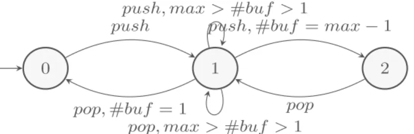
Figure5 shows the states of a connector for popping and pushing messages. It is shown that if the state is 0 for waiting to receive a message from a caller and a message is pushed into the buffer, it changes its states from 0 to 1. If its current state is 1 for waiting to receive a message from a caller or retrieving a message from a receiver, it shows that if an event pop or pull happens and the buffer has more than one message but is not full, then it stays in the state 1. Otherwise, if a pop occurs and the buffer only has one message, it changes its state from 1 to 0. But if a push occurs and the buffer is full minus 1 message, it changes its state from 1 to 2 for retrieving messages from a receiver. Finally, it shows that to change from state 2 to 1 only a pop event is required.
Fig. 5. States of a MPS FIFO connector
4.3 Remote Procedure Call
In the typical remote procedure call (RPC) communication style [3], a channel is used for sending invocation (request) messages from a client to a server and for receiving acknowledgement (reply) messages from a server to a client. The communication channel is modeled as a queue of fixed length for both request and reply messages from a client and a server respectively. Note that RPC is a special case of the general message-passing model.
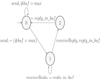
Figure6 shows the states of a client for sending invocation messages and receiving reply messages. It is shown that if the state for send is sending and the buffer is not full, it changes its state from 0 (invocation sent) to 1 for waiting for a reply. On the other hand, if the state is sending and the buffer is full, it remains at state 0. It is also shown that if the state is waiting to receive a reply (1) and the reply is in the buffer, it changes its state from 1 to 2 for receiving a reply. Otherwise, if the reply is not yet in the buffer, it remains at state 1. On the other hand, if the state is receiving and the reply is not in the buffer, it changes its state from 2 to 0.
Figure7 shows the states of a connector for pushing and pulling invocation and reply messages. It is shown that if the state is waiting to receive from the caller (0) and a push of an invocation occurred, it changes its state from 0 to 1. The connector stays in state of retrieving an invocation to the receiver (1) until a pull of an invocation which changes its state from 1 to 2 for waiting for a reply. Figure7 also shows also that the connector remains in this new state until a push of a reply occurs then it changes its states from 2 to 3 indicating that it
is receiving a reply. Finally, it changes its state from 3 to 0 if a pull of a reply occurred.
Fig. 6. States of a client for invocation/receiving reply messages
Fig. 7. States of a RPC connector
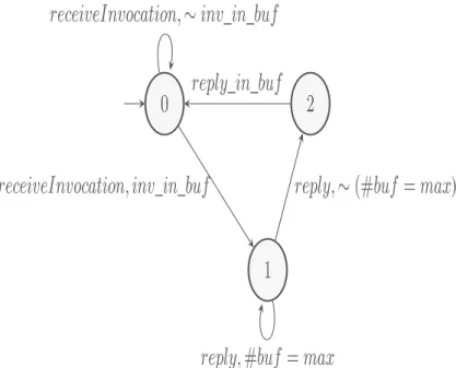
Figure8 shows the states of a server for receiving invocation and sending reply messages. It is shown that if the state is waiting to receive an invocation and an event receiveInvocation occurs in the case that an invocation is present in the buffer it changes it state from 0 to 1. Otherwise, if the invocation is absent it remains in the same state. It also shows that after the execution when an event reply, if the buffer is not full it changes its state from 1 to 2. Otherwise, if the buffer is full it stays in state 1. Finally, from state 2 it returns to state 0 when a reply is in the buffer.
Fig. 8. States of a server for receiving invocation/sending reply message
5
Formalization and Verification
In this section, we discuss the definition of our software architecture metamodel in Alloy, followed by the specification and verification of the connectors. It con-sists of a set of definitions, facts, predicates, assertions and functions. We attempt to formalize software architecture models and their semantics following some properties (specifications) to check architectural conformance. We facilitate this by providing an architectural meta model in Alloy, that incorporates the con-cepts of the metamodel presented in Sect.3and involves new concepts to capture the behavioral aspects of the specific communication styles.
5.1 Software Architecture Metamodel in Alloy
A software architecture as described in Sect.3is mapped to our Alloy meta model as follows. The mapping of structural elements is straightforward. An architec-tural component, port, connector, interface, methods, and data are mapped to their namesake types in Alloy, as are nodes and links. Before two (or more) components can interact, we assume that a connector must be present between them. We used the Time module provided within Alloy, where time is explicitly modeled as a set of discrete, ordered Time instances. Therefore, associations (such as the set of ports connected by one connector) can be made by adding a relationship with the Time set (i.e., the connects relationship that relates con-nector to port is a relationship from concon-nector over port to Time). Furthermore, if a connector exists between components on different nodes, then there must be a corresponding link between those nodes to host the Connector.
A component is connected to a connector through a number of ports. The three basic concepts in the model are components, ports and connectors that are represented as a set of Alloy signatures as depicted in Listing 1.1. With
regard to the scenario view, we defined two additional concepts: MsgPassing and Invocation. Each of them is created by the client and consumed by the server. For instance, once a send is executed by the sender component, MsgPassing is buffered in a connector. When it is received by the receiving component, it is removed from the connector.
s i g P o r t {} s i g Component { u s e s : s e t P o r t } a b s t r a c t s i g C o n n e c t o r { c o n n e c t s : s e t P o r t −> Time }{ a l l d i s j c1 , c 2 : Component , t : Time { c 1 . u s e s + c 2 . u s e s i n c o n n e c t s . t i m p l i e s some n1 , n2 : Node { c 1 i n n1 . h o s t s . t c 2 i n n2 . h o s t s . t n1 = n2 or some l : L i n k | n1+n2 i n l . c o n n e c t s . t } } } a b s t r a c t s i g C h a n n e l extends C o n n e c t o r { d i s j p o r t I , portO : one P o r t }{ a l l t : Time | c o n n e c t s . t = p o r t I + portO } a b s t r a c t s i g C o m m u n i c a t i o n A r t i f a c t { c l i e n t : one Component , s e r v e r : one Component }{ c l i e n t != s e r v e r } s i g M s g P a s s i n g extends C o m m u n i c a t i o n A r t i f a c t { msgData : one M e s s a g e
msgType : one DataType
} s i g I n v o c a t i o n extends C o m m u n i c a t i o n A r t i f a c t { i n v o c a t i o n o f : one Method , a r g u m e n t s c a l l : s e t Argument , a r g u m e n t s r e p l y : s e t Argument −> Time }
Listing 1.1. Software architecture metamodel in Alloy
5.2 Formal Specification of the Connectors
Listings 1.2, 1.3 and 1.4 depict an excerpt of the formalization of the three studied connectors, respectively message passing connector, message passing with FIFO ordering connector and remote procedure call connector. The semantics of these connectors are the same as those of the modeling presented in Sect.4. To specify the behavior of a connector, we use traces of computation which is a common technique in Alloy. For each connector we define a trace of computation as a sequence of states. To model a trace in Alloy, we reuse the Alloy standard ordering module which creates a single linear ordering over the instances of the signature provided as its input. Therefore, we provide a fact that puts a constraint on the behavior of the connector. For example, in Listing 1.2, the fact constrains the acceptable state transitions of the message passing connector to form a valid executable trace.
s i g ConnectorMPS extends C h a n n e l { b u f f e r : s e t M s g P a s s i n g −> Time , c a p a c i t y : I n t } pred M P S i n i t [ t : Time ] { a l l c : ConnectorMPS | # c . b u f f e r . t = 0 }
pred MPS push [ t , t ’ : Time , c : ConnectorMPS , mp : M s g P a s s i n g ] { #c . b u f f e r . t < c . c a p a c i t y
}
pred MPS pull [ t , t ’ : Time , c : ConnectorMPS , mp : M s g P a s s i n g ] { mp i n c . b u f f e r . t
c . b u f f e r . t ’ = c . b u f f e r . t − mp }
f a c t t r a c e s {
M P S i n i t [TO/ f i r s t ]
a l l t : Time − TO/ l a s t | l e t t ’ = TO/ n e x t [ t ] |
some c : ConnectorMPS , mp : M s g P a s s i n g | MPS push [ t , t ’ , c , mp ] or MPS pull [ t , t ’ , c , mp ]
}
Listing 1.2. Message passing connector
s i g QMessage extends QElem {
m e s s a g e : one M s g P a s s i n g }
s i g ConnectorMPSFIFO extends C h a n n e l { b u f f e r : one Queue ,
}
pred MPSFIFO init [ t : Time ] {
a l l c : ConnectorMPSFIFO | QEmpty [ t , c . b u f f e r ] }
pred MPSFIFO push [ t , t ’ : Time , c : ConnectorMPSFIFO , mp : M s g P a s s i n g ] { one qm : QMessage | qm . m e s s a g e = mp and QEnq [ t , t ’ , c . b u f f e r , qm ] }
pred MPSFIFO pop [ t , t ’ : Time , c : ConnectorMPSFIFO , mp : M s g P a s s i n g ] { QLast [ t , c . b u f f e r ] . m e s s a g e = mp
QDeq [ t , t ’ , c . b u f f e r ] }
f a c t t r a c e s {
MPSFIFO init [TO/ f i r s t ]
a l l t : Time − TO/ l a s t | l e t t ’ = t . n e x t |
some mp : M s g P a s s i n g , c : ConnectorMPSFIFO | MPSFIFO push [ t , t ’ , c , mp ]
or MPSFIFO pop [ t , t ’ , c , mp ]
}
Listing 1.3. Message passing with FIFO ordering connector
s i g ConnectorRPC extends C h a n n e l { b u f f e r : I n v o c a t i o n l o n e −> Time } pred R P C I n i t [ t : Time ] { a l l c : ConnectorRPC | c . b u f f e r . t = none }
pred RPC push [ t , t ’ : Time , c : ConnectorRPC , i : I n v o c a t i o n ] { c . b u f f e r . t = none
c . b u f f e r . t ’ = i }
pred R P C p u l l [ t , t ’ : Time , c : ConnectorRPC , i : I n v o c a t i o n ] { c . b u f f e r . t = i
c . b u f f e r . t ’ = none }
pred R P C p u s h I n v o c a t i o n [ t , t ’ : Time , c : ConnectorRPC , i : I n v o c a t i o n ] { # c . b u f f e r . t . a r g u m e n t s r e p l y . t = 0
RPC push [ t , t ’ , c , i ] }
pred R P C p u l l I n v o c a t i o n [ t , t ’ : Time , c : ConnectorRPC , i : I n v o c a t i o n ] { # c . b u f f e r . t . a r g u m e n t s r e p l y . t = 0
R P C p u l l [ t , t ’ , c , i ] }
pred RPC pushReply [ t , t ’ : Time , c : ConnectorRPC , r : I n v o c a t i o n ] { # c . b u f f e r . t . a r g u m e n t s r e p l y . t ’ != 0
RPC push [ t , t ’ , c , r ] }
pred R P C p u l l R e p l y [ t , t ’ : Time , c : ConnectorRPC , r : I n v o c a t i o n ] { # c . b u f f e r . t . a r g u m e n t s r e p l y . t != 0
R P C p u l l [ t , t ’ , c , r ] }
f a c t t r a c e s {
R P C I n i t [TO/ f i r s t ]
a l l t : Time − TO/ l a s t | l e t t ’ = TO/ n e x t [ t ] | some c : ConnectorRPC , i : I n v o c a t i o n , r : I n v o c a t i o n
| R P C p u s h I n v o c a t i o n [ t , t ’ , c , i ] i f f not R P C p u l l I n v o c a t i o n [ t , t ’ , c , i ] i f f not RPC pushReply [ t , t ’ , c , r ] i f f not R P C p u l l R e p l y [ t , t ’ , c , r ] }
5.3 Formal Specification of the Communication Primitives
Moreover, we define the corresponding communication primitives associated with each of the corresponding communication styles. The semantics of these primi-tives are the same as those of the modeling presented in Sect.4.
Message Passing Communication. Communication in the message passing communication style is performed using the send() and receive() primitives. The send() primitive requires the name of the receiver component, the trans-mitted data and the expected data types as parameters, while the receive() primitive requires the name of the anticipated sender component and should provide storage variables for the message data and the expected data types (see Listing 1.5).
In spite of blocking primitives that are often chosen, for the sake of easier realization, here we consider the semantics of a non-blocking primitives to cap-ture the more general asynchronous communication paradigm. The non-blocking send(receiver, data) returns control to the sender immediately and the message transmission process is then executed concurrently with the sender process. The sender executes a send(receiver, data) which results in the communication sys-tem constructing a message and sending it to the receiver through the corre-sponding connector. The receiver executes a receive(sender, data) which causes the receiver to be blocked, awaiting a message from the sender. When the mes-sage is received, the communication system removes the mesmes-sage from the cor-responding connector, extracts the data from the message and delivers it to the receiver. As a prerequisite, we added the check type interaction data predicate to ensure that message’s types are supported at both the sending and receiving components. Without data type checking, the support of the message type is only verified at execution time.
pred c h e c k t y p e i n t e r a c t i o n d a t a [ mp : M s g P a s s i n g ] {
one d i : Data , p : mp . c l i e n t . u s e s | d i i n p . r e a l i z e s and d i . k i n d = DATA OUT and
mp . msgType i n d i . DataType
one d i : Data , p : mp . s e r v e r . u s e s | d i i n p . r e a l i z e s and d i . k i n d = DATA IN and
mp . msgType i n d i . DataType
}
pred Component . s e n d [ r e c e i v e r : Component , d : Message , t y p : DataType , t : Time ] { some mp : M s g P a s s i n g { mp . c l i e n t = t h i s mp . s e r v e r = r e c e i v e r mp . msgData = d mp . msgData . msgType= t y p c h e c k t y p e i n t e r a c t i o n d a t a [ mp ]
one t ’ : t . n e x t | l e t c = { c : ConnectorMPS | c . portO i n mp . c l i e n t . u s e s and c . p o r t I i n mp . s e r v e r . u s e s } | MPS push [ t , t ’ , c , mp ]
} }
pred Component . r e c e i v e [ s e n d e r : Component , d : Message , t y p : DataType , t : Time ] { some mp : M s g P a s s i n g { mp . c l i e n t = s e n d e r mp . s e r v e r = t h i s mp . msgData = d mp . msgData . msgType= t y p c h e c k t y p e i n t e r a c t i o n d a t a [ mp ]
one t ’ : t . n e x t | l e t c = { c : ConnectorMPS | c . portO i n mp . c l i e n t . u s e s and c . p o r t I i n mp . s e r v e r . u s e s } | MPS pull [ t , t ’ , c , mp ]
} }
Listing 1.5. Message passing communication
Remote Procedure Call Communication. Communication in the remote pro-cedure call communication style is performed using the call(), executeCall(), reply() and executeReply() primitives. As depicted in Listing 1.6, the call()
primitive executed at the caller component requires the name of the callee com-ponent providing the invoked method, the method being invoked and the asso-ciated arguments as parameters. The executeCall() primitive requires the name of the anticipated caller component, the corresponding invoked method and its input and output arguments. The reply() primitive requires the name of the anticipated caller component, the corresponding invoked method and its result parameters. The executeReply() primitive requires the name of the anticipated callee component, the corresponding invoked method and its result parameters. The semantics of RPC in distributed systems are the same as those of a local procedure call in a non distributed systems: The caller component calls and passes input arguments to the remote procedure and it blocks at the call(callee, method, input, result) while the remote procedure executes (executeCall(caller, method, input, result)). When the remote procedure com-pletes, the callee component can return result parameters to the calling compo-nent (reply(caller, method, result)) and the caller becomes unblocked and con-tinues its execution (executeReply(callee, meth, result)). As a prerequisite, we added the check type interaction interface predicate to ensure that operations are present at the sending and receiving components before an invocation is exe-cuted. Without interface type checking, the presence of the invoked operation is only verified at execution time.
pred c h e c k t y p e i n t e r a c t i o n i n t e r f a c e [ i : I n v o c a t i o n ] {
one i f : I n t e r f a c e , p : i . c l i e n t . u s e s | i f i n p . r e a l i z e s and i f . k i n d = REQUIRED and i . i n v o c a t i o n o f i n i f . methods
one i f : I n t e r f a c e , p : i . s e r v e r . u s e s | i f i n p . r e a l i z e s and i f . k i n d = PROVIDED and i . i n v o c a t i o n o f i n i f . methods
}
pred Component . c a l l [ c a l l e e : Component , meth : Method , i n: s e t Argument , o u t : s e t Argument , t : Time ] { some i : I n v o c a t i o n { i . c l i e n t = t h i s i . s e r v e r = c a l l e e i . i n v o c a t i o n o f = meth i . a r g u m e n t s c a l l = i n # i . a r g u m e n t s r e p l y . t = 0 c h e c k t y p e i n t e r a v t i o n i n t e r f a c e [ i ]
one t ’ : t . n e x t | l e t c = { c : ConnectorRPC | c . portO i n i . c l i e n t . u s e s and c . p o r t I i n i . r e c e i v e r . u s e s } | R P C p u s h I n v o c a t i o n [ t , t ’ , c , i ] }
}
pred Component . e x e c u t e C a l l [ c a l l e r : Component , meth : Method , i n: s e t Argument , o u t : s e t
Argument , t : Time ] { some i : I n v o c a t i o n { i . c l i e n t = c a l l e r i . s e r v e r = t h i s i . i n v o c a t i o n o f = meth i . a r g u m e n t s c a l l = i n # i . a r g u m e n t s r e p l y . t = 0 c h e c k t y p e i n t e r a c t i o n i n t e r f a c e [ i ]
one t ’ : t . n e x t | l e t c = { c : ConnectorRPC | c . portO i n i . c l i e n t . u s e s and c . p o r t I i n i . s e r v e r . u s e s }
| R P C p u l l I n v o c a t i o n [ t , t ’ , c , i ] and c . b u f f e r . t ’ . a r g u m e n t s r e p l y . t ’ = a r g s o u t }
}
pred Component . r e p l y [ c a l l e r : Component , meth : Method , o u t : s et A r g u m e n t , t : Time ] { some r : I n v o c a t i o n { r . c l i e n t = c a l l e r r . s e r v e r = t h i s i . i n v o c a t i o n o f = meth i . a r g u m e n t s c a l l = i n i . a r g u m e n t s r e p l y = o u t c h e c k t y p e i n t e r a c t i o n i n t e r f a c e [ i ]
one t ’ : t . n e x t | l e t c = { c : ConnectorRPC | c . portO i n r . c l i e n t . u s e s and c . p o r t I i n r . s e r v e r . u s e s }
| RPC pushReply [ t , t ’ , c , r ] }
}
pred Component . e x e c u t e R e p l y [ c a l l e e : Component , meth : Method , i n: s e t Argument , o u t : s e t
Argument , t : Time ] {
some r : I n v o c a t i o n { r . c l i e n t = t h i s
r . s e r v e r = c a l l e e i . i n v o c a t i o n o f = meth i . a r g u m e n t s c a l l = i n i . a r g u m e n t s r e p l y = o u t
c h e c k t y p e i n t e r a c t i o n i n t e r f a c e [ i ]
one t ’ : t . n e x t | l e t c = { c : ConnectorRPC | c . portO i n r . c l i e n t . u s e s and c . p o r t I i n r . s e r v e r . u s e s }
| R P C p u l l R e p l y [ t , t ’ , c , r ] }
}
Listing 1.6. Remote procedure call communication
5.4 Formal Verification and Results
To analyze the connectors, the modeling formalism developed in this work allows to specify the properties to be checked in terms of first-order predicate logic formulas. Then, the Alloy Analyzer automatically checks the properties using a SAT solver. Among the set of possible and yet specified characteristics of the behaviors of the message passing and remote procedure call communication styles, a subset of them are encoded in terms of properties as predicates and assertions and the results of their verification are stated below.
Some of the properties that are specified and verified reflect typical liveness properties of concurrent and communicating systems. In order to ensure that such systems are dependable, liveness properties such as property (a) given below for both message passing and remote procedure call communication are vital to ensuring reliable communications and system behaviors.
– Message passing communication.
• (a) “once the client c1 sends a message to server s1, eventually that server receives it”.
pred s e n d e v e n t u a l l y r e c e i v e d {
one t : Time | one t ’ : t . n e x t s | some c1 , c 2 : Component | some d : M e s s a g e | some t y p : DataType |
c 2 . s e n d [ c1 , d , typ , t ’ ] => c 1 . r e c e i v e [ c2 , d , typ , t ] }
• (b) “once the server s1 receives a message, it must already have been sent by a certain client c1”.
a s s e r t r e c i e v e m u s t b e s e n t {
one t : Time | one t ’ : t . n e x t s | some c1 , c 2 : Component | some d : M e s s a g e | some t y p : DataType |
c 2 . r e c e i v e [ c1 , d , typ , t ’ ] => c 1 . s e n d [ c2 , d , typ , t ] }
• (c) “messages sent from the client c1 to the server s1 reach the server s1 in the same order as they were sent from c1”.
a s s e r t i s F I F O {
a l l d i s j c1 , s 1 : Component | a l l d i s j d1 , d2 : M e s s a g e | some typ1 , t y p 2 : DataType | a l l t s 1 : Time | l e t t s 2 = t s 1 . n e x t s | a l l t r 1 : Time | a l l t r 2 :
Time |
( c 1 . s e n d [ s 1 , d1 , typ1 , t s 1 ] and c 1 . s e n d [ c2 , d2 , typ2 , t s 2 ] and s 1 . r e c e i v e [ c1 , d1 , typ1 , t r 1 ]
and s 1 . r e c e i v e [ c1 , d2 , typ2 , t r 2 ] ) => t r 2 i n t r 1 . n e x t s
}
The Alloy Analyzer shows that properties (a) and (b) hold for both types of message passing connector (simple and FIFO). It also shows that prop-erty (c) does not hold for a simple message passing connector. Since the
property does not hold, Alloy produces a counter example, which shows the main reason why the specified property does not hold. However, the Alloy analyzer shows that this property holds for a FIFO ordered message passing connector.
– Remote procedure call communication.
• (a) “Once the caller c1 sends an invocation to callee c2, the caller even-tually receives an acknowledgement from that callee”.
pred s e n d i s e v e n t u a l l y r e p l i e d {
one t : Time | one t ’ : t . n e x t s | some c1 , c 2 : Component | some m: Method
| some a r g s i n : Argument | some a r g s o u t : Argument |
c 1 . c a l l [ c2 , m, a r g s i n , a r g s o u t , t ] => c 1 . e x e c u t e R e p l y [ c2 , m, a r g s i n , a r g s o u t , t ’ ]
}
• (b) “Once the caller c1 receives results corresponding to an invocation of a method m at a certain server c2 and the caller c1 starts the next invo-cation of the same method at the same server, the callee c1 is eventually executing that invocation”.
pred r e p l y a n d c a l l i s e v e n t u a l l y r e c e i v e d {
one t : Time | one t ’ : t . n e x t s | one t ’ ’ : t ’ . n e x t |
some c1 , c 2 : Component | some m: Method |
some d i s j a r g s i n 1 , a r g s o u t 1 , a r g s i n 2 , a r g s o u t 2 : Argument |
c 2 . r e p l y [ c1 , m, a r g s i n 1 , a r g s o u t 1 , t ] and c 1 . c a l l [ c2 , m, a r g s i n 2 , a r g s o u t 2 , t ’ ] =>
c 2 . e x e c u t e C a l l [ c1 , m, a r g s i n 2 , a r g s o u t 2 , t ’ ’ ] }
The Alloy Analyzer shows that both properties (a) and (b) hold for a RPC connector.
6
Use Case
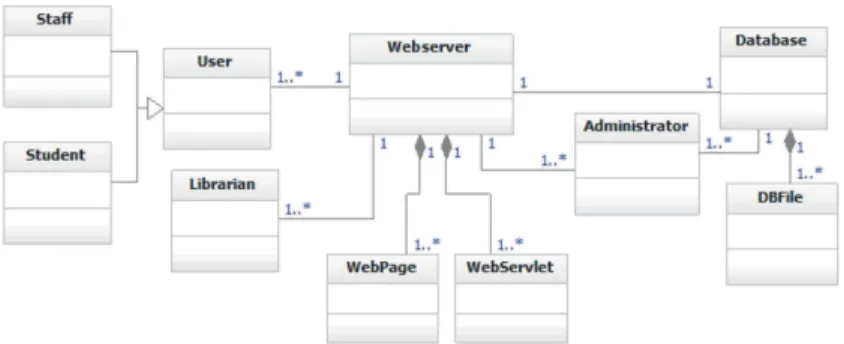
We use a college library website system [19] to exemplify the proposed app-roach. Figure9 shows the overall architecture description of the web application. It consists of a the following software components: a client, a web server and a database server. The website provides online services for searching for and requesting books. The users are students, college staff and librarians. Staff and students will be able to log in and search for books, and staff members can request books. Librarians will be able to log in, add books, add users, and search for books. We use a UML class diagram to describe the high level architecture model of the web application, where software components are represented by classes, and connectors between these components are represented by associa-tions. However, effective realizations of these connectors are not modeled in the UML class diagram; they may be subject to certain changes and/or adapta-tions (e.g., new soluadapta-tions, deleadapta-tions, modificaadapta-tions of realization), verificaadapta-tions (e.g., formal verification) and reuse (e.g., in the same domain or across domains) while the structure of the main software architecture can be maintained. Each connector represents a communication pattern which rigorous software develop-ers, mainly architects would like software modeling and analysis languages to easily express.
Fig. 9. A web application example in UML
6.1 Expressing the Architecture of a Web Application Example Listing 1.7 depicts the Alloy specification of the web application architecture described in Fig.9. We start by defining the component types, and the interfaces and connectors as simple extensions to the concepts of our software architecture metamodel. Then, we reuse our connector models, the corresponding commu-nication primitives and their associated properties to specify the structure and the behavior of the software architecture describing the example in Alloy.
one s i g U s e r B r o w s e r extends Component { }{
u s e s = P o r t I n t e r f a c e B r o w s e r }
one s i g W e b s e r v e r extends Component { }{
u s e s = P o r t I n t e r f a c e W e b s e r v e r + P o r t D a t a W e b s e r v e r }
one s i g D a t a b a s e extends Component { }{ u s e s = P o r t D a t a D a t a b a s e } one s i g I n t e r f a c e B r o w s e r extends I n t e r f a c e { }{ g e t B o o k i n methods } one s i g I n t e r f a c e W e b s e r v e r extends I n t e r f a c e { }{ g e t B o o k i n methods }
one s i g D a t a W e b s e r v e r extends Data { }
one s i g D a t a D a t a b a s e extends Data { } one s i g P o r t I n t e r f a c e B r o w s e r extends P o r t { }{ r e a l i z e s = I n t e r f a c e B r o w s e r } one s i g P o r t I n t e r f a c e W e b s e r v e r extends P o r t { }{ r e a l i z e s = I n t e r f a c e W e b s e r v e r } one s i g P o r t D a t a W e b s e r v e r extends P o r t { }{ r e a l i z e s = D a t a W e b s e r v e r } one s i g P o r t D a t a D a t a b a s e extends P o r t { }{ r e a l i z e s = D a t a D a t a b a s e }
one s i g B r o w e r W e b s e r v e r C o n n e c t o r extends ConnectorRPC { }{
portO = P o r t I n t e r f a c e B r o w s e r p o r t I = P o r t I n t e r f a c e W e b s e r v e r }
one s i g D a t a b a s e W e b s e r v e r C o n n e c t o r extends ConnectorMPS { }{
portO = P o r t D a t a D a t a b a s e p o r t I = P o r t D a t a W e b s e r v e r }
6.2 Expressing and Verifying Functional Requirements
To illustrate the usage of the developed model, we studied two functional require-ments of the example. Listing 1.8 depicts their encoding in Alloy. Then, the architect can verify whether these two requirements hold using the Alloy ana-lyzer.
– Req 1. It should be possible for somebody to visualize a book page.
– Req 2. It should be possible for the database to transmit data to the Webserver.
pred R e q 1 {
some ws : W eb s i t e , bw : B r o ws er , op : get B o o k , a r g s i n , a r g s o u t : s e t Argument , t : Time , t ’ : t . n e x t s |
bw . c a l l [ ws , op , a r g s i n , a r g s o u t , t ] and bw . e x e c u t e R e p l y [ ws , op , a r g s i n , a r g s o u t , t ’ ] }
pred R e q 2 {
some ws : Webs er ver , db : D a t a b a s e , c : Message , t y p : DataType , t : Time , t ’ : t . n e x t s |
db . s e n d [ ws , c , typ , t ] and ws . r e c e i v e [ db , c , typ , t ’ ] }
Listing 1.8. Examples of requirements of a web application
The Alloy analyzer shows that both Req 1 and Req 2 hold, within the specified scope. This check enforces that the model is complete w.r.t. the current level of design.
7
Concluding Remarks and Future Works
Formalization and verification techniques are useful in the rigorous development of computer-based systems. In this paper, our experience in verifying message passing and RPC communication styles using Alloy is presented. Here, we have verified some most common properties of these two styles of communication and found that the properties hold. Thus from our experience we can say that the connectors and the software architecture using them are verifiable for building reliable distributed systems. Our next goal is to improve our Patten Based Sys-tem Engineering (PBSE) framework [7] considering security and safety require-ments within software architectures built on-top of these communication styles. We plan to transform our PBSE pattern modeling concepts to Alloy specifica-tions to ensure semantic validation. In addition, we aim at refining our model-ing framework with properties and reasonmodel-ing of Security Modelmodel-ing Framework (SeMF) [6]. Our starting point is modeling security patterns in Alloy from [8]. Moreover, some timing and/or other resource constraints can also be enforced to verify the architecture models.
References
1. Alloy Analyzer. http://alloy.mit.edu. Accessed June 2017
2. Allen, R., Garlan, D.: A formal basis for architectural connection. ACM Trans. Softw. Eng. Methodol. 6(3), 213–249 (1997)
3. Coulouris, G., Dollimore, J., Kindberg, T., Blair, G.: Distributed Systems: Con-cepts and Design, 5th edn. Addison-Wesley Publishing Company, Boston (2011) 4. Crnkovic, I.: Component-based software engineering for embedded systems. In:
Proceedings of the 27th International Conference on Software Engineering, ICSE 2005, pp. 712–713. ACM (2005)
5. Garlan, D.: Formal modeling and analysis of software architecture: components, connectors, and events. In: Bernardo, M., Inverardi, P. (eds.) SFM 2003. LNCS, vol. 2804, pp. 1–24. Springer, Heidelberg (2003). https://doi.org/10.1007/978-3-540-39800-4 1
6. Hamid, B., G¨urgens, S., Fuchs, A.: Security patterns modeling and formalization for pattern-based development of secure software systems. Innov. Syst. Softw. Eng. 12(2), 109–140 (2016)
7. Hamid, B., Perez, J.: Supporting pattern-based dependability engineering via model-driven development: approach, tool-support and empirical validation. J. Syst. Softw. 122, 239–273 (2016)
8. Heyman, T., Scandariato, R., Joosen, W.: Reusable formal models for secure soft-ware architectures. In: Joint Working IEEE/IFIP Conference on Softsoft-ware Archi-tecture and European Conference on Software ArchiArchi-tecture, pp. 41–50 (2012) 9. Hoare, C.A.R.: Communicating sequential processes. Commun. ACM 21(8), 666–
677 (1978)
10. Jackson, D.: Software Abstractions: Logic, Language, and Analysis. The MIT Press, Cambridge (2006)
11. Khosravi, R., Sirjani, M., Asoudeh, N., Sahebi, S., Iravanchi, H.: Modeling and analysis of Reo connectors using alloy. In: Lea, D., Zavattaro, G. (eds.) COORDI-NATION 2008. LNCS, vol. 5052, pp. 169–183. Springer, Heidelberg (2008).https:// doi.org/10.1007/978-3-540-68265-3 11
12. Kruchten, P.: Architectural blueprints - the “4+1” view model of software archi-tecture. IEEE Softw. 12(6), 42–50 (1995)
13. OMG: CORBA Specification, Version 3.1. Part 3: CORBA Component Model (2008). http://www.omg.org/spec/CCM. Accessed Nov 2009
14. OMG. OMG Systems Modeling Language (OMG SysML), Version 1.1 (2008).
http://www.omg.org/spec/SysML/1.1/,. Accessed Jan 2013
15. OMG: Object Constraint Language (OCL), Version 2.2 (2010). http://www.omg. org/spec/OCL/2.2. Accessed Jan 2013
16. OMG: UML profile for Modeling and Analysis of Real-Time and Embedded Systems (MARTE), Version 1.1 (2011).http://www.omg.org/spec/MARTE/1.1/. Accessed Jan 2013
17. OMG: Unified Modeling Language (UML), Version 2.4.1 (2011).http://www.omg. org/spec/UML/2.4.1. Accessed Jan 2013
18. OMG: Unified Component Model for Distributed, Real-Time And Embedded Sys-tems, Version 1.0 (2017). http://www.omg.org/spec/UCM/20170601/. Accessed Jan 2018
19. OWASP: Application threat modeling (2017).https://www.owasp.org/index.php/ Application Threat Modeling. Accessed Dec 2017
20. Alur, R., Dill, D.: The theory of timed automata. In: de Bakker, J.W., Huizing, C., de Roever, W.P., Rozenberg, G. (eds.) REX 1991. LNCS, vol. 600, pp. 45–73. Springer, Heidelberg (1992). https://doi.org/10.1007/BFb0031987
21. Ravi, S., Raghunathan, A., Kocher, P., Hattangady, S.: Security in embedded sys-tems: design challenges. ACM Trans. Embed. Comput. Syst. 3(3), 461–491 (2004) 22. Taylor, R.N., Medvidovic, N.: Software Architecture: Foundation, Theory, and
Practice. Wiley, Hoboken (2010)
23. Rodano, M., Giammarc, K.: A formal method for evaluation of a modeled system architecture. Procedia Comput. Sci. 20, 210–215 (2013)
24. SAE: Architecture Analysis & Design Language (AADL) (2009). http://www.sae. org/technical/standards/AS5506A. Accessed Jan 2011
25. Selic, B.: The pragmatics of model-driven development. IEEE Softw. 20(5), 19–25 (2003)
26. Zurawski, R.: Embedded systems in industrial applications - challenges and trends. In: International Symposium on Industrial Embedded Systems (SIES). IEEE (2007)