HAL Id: pastel-00547497
https://pastel.archives-ouvertes.fr/pastel-00547497
Submitted on 16 Dec 2010
HAL is a multi-disciplinary open access archive for the deposit and dissemination of sci-entific research documents, whether they are pub-lished or not. The documents may come from teaching and research institutions in France or abroad, or from public or private research centers.
L’archive ouverte pluridisciplinaire HAL, est destinée au dépôt et à la diffusion de documents scientifiques de niveau recherche, publiés ou non, émanant des établissements d’enseignement et de recherche français ou étrangers, des laboratoires publics ou privés.
Nanostructured carbons from cellulose-derivative-based
aerogels for electrochemical energy storage and
conversion: evaluation as EDLC electrode material
Claudia Hildenbrand
To cite this version:
Claudia Hildenbrand. Nanostructured carbons from cellulose-derivative-based aerogels for electro-chemical energy storage and conversion: evaluation as EDLC electrode material. Other. École Na-tionale Supérieure des Mines de Paris, 2010. English. �NNT : 2010ENMP0022�. �pastel-00547497�
N°: 2009 ENAM XXXX Rue C
École doctorale n° 4
Nanostructured carbo
for electrochemical e
E
Carbones nanostructurés à b stockage électrochimique Directeurs de JuryMme Cathie VIX, DR, IS2M Institut de Sci
M. Angel LINARES-SOLANO, Prof., D
M. Jean-Paul PIRARD, Professeur, Dép
M. Philippe AZAÏS, Docteur, BATSCAP Mme Sandrine BERTHON-FABRY, D
M. Arnaud RIGACCI, Docteur HDR, Cen
po
l’École natio
MINES ParisTech Centre Energétique et Procédés
Claude Daunesse, 06904 Sophia Antipolis Cedex, Fran
432 : SMI - Sciences des Métiers de
présentée et soutenue publiquement par
Claudia HILDENBRAND
le 9 Septembre 2010
bons from cellulose-derivative
energy storage and conversio
EDLC electrode material
base d'aérogels d'acétate de cellulose po ue d'énergie: évaluation en tant que matér
supercondensateur
e thèse : Sandrine Berthon-Fabry & Arnaud Rig
ciences des Matériaux de Mulhouse P
Departamento de química inorgánica, Universidad de Alicante
R
partement de chimie appliquée, Université de Liège, Belgique
R E
Docteur HDR, Centre Energétique et Procédés, MINES Paris
E
ntre Energétique et Procédés, MINES Paristech E
Doctorat ParisTech
T H È S E
pour obtenir le grade de docteur délivré par
tionale supérieure des mine
Spécialité “ Energétique ”
nceT
H
È
S
E
e l’Ingénieur
e-based aerogels
ion: evaluation as
our la conversion et le ériau d'électrode de igacci Président te, Espagne Rapporteur Rapporteur Examinateur istech Examinateur Examinateur arnes de Paris
Remerciements
Je tiens à remercier ici toutes les personnes qui m’ont aidée à réaliser ce travail de thèse.
Je pense bien sûr dans un premier temps à Sandrine et Arnaud, qui ont suivi ce travail de très près, et qui se sont toujours rendus très disponibles tout au long de ces trois ans. Leur gentillesse et la pertinence de leurs conseils ont eu une influence très positive sur la qualité de ce travail.
Je pense ensuite à Pierre Ilbizian, Patrick Leroux, Suzanne Jacomet et Monique Repoux, qui m’ont beaucoup aidée avec mes travaux expérimentaux et les caractérisations.
Je pense aussi à Bartosz Grzyb, Nathalie Job, Bernard Simon, Christophe Fargeau, Romain Sescousse, Tania Budtova, Philippe Azaïs et tous les membres du projet CARBOCELL, avec lesquels j’ai eu de nombreuses collaborations fructueuses.
De manière plus générale, je pense au groupe EM&P et à sa bonne humeur, ainsi qu’à tous les membres du CEP et du centre de l’Ecole des Mines de Paris de Sophia-Antipolis grâce à qui j’ai pu passer trois années très agréables dans un cadre propice à un travail scientifique de qualité.
Je remercie finalement l’ANR/Capenergies ainsi que l’association Armines pour leur soutien financier.
5
GENERAL INTRODUC TION 11
CHAPTER I: STATE OF TH E ART 15
1. CARBON IN ELECTROCHEMICAL ENERGY STORAGE, CONVERSION, AND ENVIRONMENTAL
PROTEC TION 17
1.1. INTRODUCTION 17
1.2. ELECTROCHEMICAL EN ERGY STOR AGE AND CONVER SION 20
1.2.1. ELECTROCHEMICAL CAPACITORS: EL ECTROCHEMICAL DOUBLE LAYER CAPACITOR (EDLC) AND
PSEUDOCAPACITOR 20
1.2.2. BATTER Y 20
1.2.3. ELECTROCHEMICAL H2STORAGE 22
1.2.4. PROTON EXCHANGE MEMBRANE FUEL CELLS (PEMFC) 22
1.3. ENVIRONMEN TAL PROTECTION 24
1.3.1. ADSORPTION 24
1.3.1.1. Chemical Energy Storage 24
1.3.1.2. Gas Separation and Adsorption of Pollutants 24
1.3.2. CATALYSIS 25
1.4. CONCLUSION 26
2. STATE OF THE ART: NANOSTRUC TURED CARBONS 26
2.1. OVER VIEW:ENGINEERED CARBON MATER IALS 26
2.2. OVER VIEW:CARBON MATERIAL 27
2.2.1. ACTIVATED CARBONS (AC) 28
2.2.2. CARBON AEROGELS (CA) 29
2.2.3. CARBON BLACKS (CB) 30
2.2.4. CARBON NANOSTRUCTURES (CN)–CARBON NANOTUBES (CNTS) 31
2.2.5. TEMPLATED CARBONS (TC) 32
2.2.6. FURTHER PROCESSES FOR SYNTHES IZING NANOSTRUCTURED CARBON MATERIAL 33
2.2.6.1. Defluorination of Polytetrafluoroethylene 34
2.2.6.2. Polymer Blend Process 34
2.2.6.3. Selection of specific Precursors 34
2.3. NANOSTRUC TURED CARBON MATERIAL DERIVED FROM BIOMASS 35
2.3.1. PYROLYSIS OF SPECIFIC BIOMAS S-BAS ED PRECURSORS 35
2.3.2. BIOMASS-BASED AC TIVATED CARBONS 35
2.3.3. BIOMASS-BASED CARBON AEROGELS 36
3. CARBON AEROGELS 36 3.1. GEL SYNTHESIS 36 3.2. DRYING 38 3.2.1. EVAPORATIV E DRYING 38 3.2.2. SUPERCRITICAL DRYING 39 3.2.3. FREEZE DRYING 40 3.3. CARBONIZATION 40 3.3.1. GENERAL DESCRIPTION 40 3.3.2. PYROLYSIS PARAMETERS 41
6
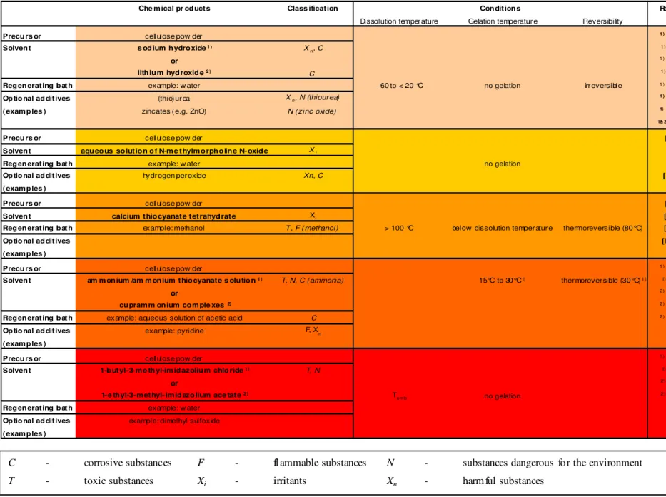
4. BIOMASS-BASED CARBON AEROGELS 43
4.1. BIOMASS-BASED PHYSICAL GELS AND WET R EGENER ATED COMPOUNDS 43
4.2. BIOMASS-BASED CHEMICAL GELS 44
4.3. SUMMARY AND SELECTION OF SYNTHESIS METHOD 49
CHAPTER II: CELLULOSE-ACETATE BASED ORGANIC AEROGELS 51
1. INTRODUC TION 53 2. EXPERIMENTAL 55 2.1. SOL-GEL SYNTHESIS 55 2.2. SUPERCRITIC AL DRYING 57 2.3. ANALYSIS METHODS 57 2.3.1. MICROGRAPHY 57
2.3.2. ANALYSIS OF POROUS CHARACTERIS TICS 57
2.3.2.1. Density, Porous Volume and Porosity 58
2.3.2.2. Specific Surface Area 59
2.3.2.3. Pore Size Distribution and Mean Pore Size 59
2.3.2.4. Specific Porous and Microporous Volume 61
2.3.3. ELEMENTAL ANALYSIS 62
2.4. INFLUENCE OF CATALYST MECHANISMS 62
3. RESULTS 68
3.1. INFLUENCE OF SOL-GEL PARAMETERS ON GELATION TIME AND SHRINKAGE 68
3.1.1. INTRODUCTION TO SOL-GEL CHARACTERISTICS 68
3.1.1.1. Gelation Time 68
3 .1 .1 .2. Shrinkage due to Syneresis 68
3.1.2. INFLUENCE OF SOL-GEL SYNTHESIS PARAMETERS ON GELATION TIM E AND SHRINKAGE 69
3 .1 .2 .1. Cellulose Acetate Concentration %CA 69
3 .1 .2 .2. Cross-linking Ratio I/CA 72
3 .1 .2 .3. Catalyst Ratio I/Cat and Type 73
3.2. INFLUENCE OF SOL-GEL PARAMETERS AND DRYING ON THE ORG ANIC AEROGEL STRUCTURE 76
3.2.1. INFLUENCE OF SOL-GEL SYNTHESIS PARAMETERS 76
3.2.1.1. Macro- and Microscopic Observation 76
3.2.1.2. Organic Aerogel Structure 80
3.2.2. INFLUENCE OF THE DRYING PROCESS ON THE ORGANIC AEROGEL STRUCTURE 88
3.2.3. ORGANIC AEROGEL ELEMENTAL COMPOSITION 90
4. CONCLUSION 91
CHAPTER III: CELLULOSE-ACETATE-BASED CARBON AEROGELS 93
7
2. EXPERIMENTAL 95
3. RESULTS AND DISCUSSION 97
3.1. EVOLUTION O F CELLULOSE-ACETATE-BASED AEROGELS DURING PYROLYSIS 97
3.1.1. MACROSCOPIC OBSERVATION 97
3.1.2. MICROGRAPHIC OBSERVATION 98
3.1.3. EVOLUTION OF CELLULOSE-ACETATE-BAS ED AEROGELS DURING PYROLYSIS 102
3.1.4. EVOLUTION OF THE SURFACE CHEMIS TRY DURING PYROLYSIS 106
3.1.5. SKELETAL DENSITY 108
3.1.6. REPRODUCIBILITY OF THE CARBON AEROGEL PREPARATION 108
3.2. INFLUENCE OF THE PRISTIN E ORGAN IC AEROGEL 108
3.2.1. INFLUENCE OF ORGANIC AEROGEL STRUCTURE ON THE CARBON AEROGEL STRUCTURE 109 3.2.2. INFLUENCE OF ORGANIC AEROGEL COMPOSITION ON CARBON AEROGEL COMPOSITION 117
3.3. INFLUENCE OF PYROLYSIS PARAM ETERS 117
3.3.1. INFLUENCE ON CARBON AEROGEL STRUCTURE 118
3.3.2. INFLUENCE ON CARBON AEROGEL COMPOSITION 121
4. CONCLUSION 124
CHAPTER IV: MODIFICATION OF THE CELLULOSE-ACETATE BASED CARBON AEROGELS - STRUCTURE
AND SURFACE CHEMISTRY 125
1. INTRODUC TION 127
2. MODIFICATION OF TH E CARBON AEROGEL STRUC TURE 127
2.1. PHYSICAL ACTIVATION 127
2.1.1. EXPERIMENTAL 128
2.1.1.1. Carbon aerogel synthesis 128
2.1.1.2. Activation 128
2.1.1.3. Structural and Chemical Analysis 128
2.1.2. RESULTS AND DISCUSSION 129
2.1.2.1. Structure 129
2.1.2.2. Elemental Composition 132
2.1.3. CONCLUSION ON ACTIVATION 132
2.2. CELLULOSE-ACETATE-B ASED AEROG EL/CELLULOSE POWDER COMPOSITES 132
2.2.1. EXPERIMENTAL 133
2.2.2. RESULTS AND DISCUSSION 133
2.2.2.1. Macro- and Microscopic Observation 133
2.2.2.2. Structural Analysis of Organic Composites 137
2.2.2.3. Structural Analysis of Carbonized Composites 138
2.2.3. CONCLUSION ON CELLULOSE-ACETATE-BASED AEROGEL/CELLULOSE POWDER COMPOSITES 140
3. MODIFICATION OF TH E CARBON AEROGEL SURFACE CHEMISTRY 140
3.1. EXPERIMEN TAL 141
8
3.1.2. CHEMICAL MODIFICATION OF THE CARBON AEROGEL 141
3.1.3. STRUCTURAL ANALYSIS 142
3.1.4. ANALYSIS OF CHEMICAL PROPERTIES 143
3.2. RESULTS AND DISCUSSION 143
3.2.1. STRUCTURE 143
3.2.2. ELEMENTAL COMPOSITION 145
3.2.3. EVOLUTION OF THE SURFACE CHEMIS TRY ON THE CHEMICAL TREATMENT OF THE CARBON AEROGELS 146
3.2.4. HETEROGENEITY OF CARBON AEROGELS 161
3.3. CONCLUSION ON THE MODIFICATION OF THE CARBON AEROG EL SURFACE CHEM ISTRY 162
4. CONCLUSION 162
CHAPTER V: ELECTROCHEMICAL ANALYSIS OF CELLULOSE-ACETATE-BASED CARBON AEROGELS ON
THE EXAMPLE OF AN EDLC 165
1. INTRODUC TION 167
2. STATE OF THE ART: EDLC 169
2.1. EDLCDESIGN 169
2.1.1. CONVENTIONAL CAPACITOR 169
2.1.2. EDLCASSEMBLY 170
2.2. IMPORTANCE OF TH E EDLCELECTRODE 171
2.3. POTENTIAL IMPROVEM ENT OF EDLCASSEMBLY 172
2.3.1. IMPROVEMENT OF ENERGY AND POWER CAPABILITIES 172
2.3.2. ELECTRODE STRUCTURE 173
2.3.3. ORGANIC ELECTROLYTES 174
2.3.4. PSEUDOCAPACITANCE 174
2.3.5. HYBRID CAPACITOR 175
2.4. TARGETED PERFORM ANCE 176
3. EXPERIMENTAL SECTION 176
3.1. EDLCTEST BENCH ASSEMBLY 176
3.2. ANALYSIS METHODS 178
3.2.1. ANALYSIS OF EDLCPERFORMANCE 178
3.2.2. CYCLIC VOLTAMMETRY 179
3.3. CARBON SAMPLES 187
4. RESULTS AND DISCUSSION 189
4.1. INFLUENCE OF TEST CELL 189
4.2. INFLUENCE OF STRUCTUR E 191
4.2.1. INTEREST OF SYNTHESIZING CARBON AEROGELS 191
4.2.2. XEROGEL PERFORMANCE 194
4.2.3. INTEREST OF ACTIVATION 197
4.2.4. PERFORMANCE OF CELLULOSE-ACETATE-B ASED AEROGEL/CELLULOSE POWDER COMPOSITES 201
9
4.3.1. INFLUENCE OF OXIDATION 205
4.3.2. INFLUENCE OF NITROGEN INTRODUCTION 209
4.4. COMPARISON WITH OTHER NANOSTRUCTURED CARBON S 213
4.4.1. COMPARISON OF DIFFERENT CELLULOSE-BASED CARBON AEROGELS 213
4.4.2. COMPARISON WITH A COMMERCIALLY AVAILABLE ACTIVATED CARBON 216
5. CONCLUSION 218
GENERAL CONCLUSI ON 221
RESUME EN LANGUE FRANÇAISE 227
REFERENCES 229
11
13 The ever-increasing utilization of fossil energy sources aggravates environmental pollution and the depletion of these energy carriers. Enhancement of energy efficiency and the valorisation of renewable resources are only two of several approaches to counteract these effects. Energy efficiency can be drastically improved by efficient energy conversion and storage of surplus or intermittent energy.
Electrochemical energy storage and conversion, as well as several devices used in environmental protection, depend amongst others on the use of suitable nanostructured carbonaceous material. Nanostructured carbon is thus used in electrochemical energy storage and conversion devices, e.g. as electrode material for fuel cells, batteries, or still EDLCs (Electric Double Layer Capacitors). Further, nanostructured carbon is employed in environmental protection, e.g. in gas separation and adsorption applications for pollution control, but also for fuel storage and as catalyst support. Carbon used in all these applications has to feature a particular structure adapted to each specific application. The structure needs to be adapted, for example in terms of high available specific surface area and pore size distribution. Being such a crucial parameter, the carbon structure has to be adjusted to each application’s requirements.
Carbon aerogels are considered to be a very promising solution for creating carbon material adjusted to the particular requirements of any of the above-mentioned applications. As aerogels are synthesized by soft chemistry, their structural properties, such as pore size and shape, density, or particle size, can be tailored simply by varying the parameters of the synthesis process [Pan 2006]. Carbon aerogels are obtained by the pyrolysis of organic aerogels. Organic aerogels are synthesized via sol-gel process allowing the use of a wide variety of precursors including renewable resources, such as biomass-derived products. This has been shown e.g. by Tan et al. [Tan 2001] who have synthesized organic aerogels based on cellulose acetate. Fischer et al. [FiR 2006] have then refined this type of aerogel synthesis using only non-toxic and non-corrosive chemical products. In addition, they have demonstrated that carbon aerogels with interesting structural features can be prepared from these biomass-based products [Gui 2007].
This PhD thesis aimed at developing a family of novel nanostructured carbons from renewable organic sol-gel precursors, i.e. cellulose-acetate-based aerogels. The underlying objective has been to create the possibility of tuning the carbon aerogels’ characteristics to the properties required for the use in different applications, by predicting the influence of the synthesis and pyrolysis parameters. Therefore, my work has been based on an experimental approach focused at creating a set of correlations between the carbon synthesis parameters and the carbons’ structure.
Even though being a crucial parameter, the carbon structure is not the only influential parameter determining the performance of a carbon used in electrochemical energy storage and conversion and environmental protection devices. The carbon surface chemistry also plays a very important role, due to inevitable interactions at the solid/fluid interphase at the carbon surface. Surface functional groups influence the carbons’ behaviour, e.g. in terms of wettability, charge transfer, blocking of reactive sites, possible redox reactions, etc. A variety of heteroatoms and therefore functional groups can be present in a carbon, depending on the precursor and on the method of preparation. In addition, heteroatoms can be added by a variety of different post-treatments. Thus, I have additionally focused on at understanding the influence of different post-treatments of the cellulose-acetate-based carbon aerogel on its chemical and physical properties through an experimental study.
14 This document is organized into five chapters as follows:
• The first chapter presents the state of the art of nanostructured carbons conventionally used in electrochemical energy storage and conversion devices, particularly of those derived from biomass.
• The second chapter examines the results of my experimental studies on creating a broad range of structurally different organic aerogels and on establishing correlations between the organic aerogel synthesis parameters (i.e. precursor and catalyst concentration and catalyst nature) and the organic aerogels’ structure.
• The third chapter describes the results of my experimental work on establishing correlations between the pyrolysis parameters (maximum pyrolysis temperature and pyrolysis atmosphere) and the resulting carbon material characteristics, in terms of structure and composition.
• The fourth chapter provides the results of different experimental studies aiming at modifying the carbon aerogels in terms of structure and surface chemistry. In order to modify the structure carbon aerogels have been activated in CO2 and cellulose-acetate-based aerogels
containing cellulose powder have been prepared. Additionally, the surface chemistry of one representative carbon sample has been modified by oxidation and/or nitrogen enrichment methods.
• The fifth chapter finally focuses on evaluating the electrochemical performance of different cellulose-acetate-based carbon aerogels synthesized during my PhD thesis. The carbon aerogels performance if being used as EDLC electrode material has been examined. The performance of cellulose-acetate-based carbon aerogels of different structures and surface chemistries has been analyzed and compared to other cellulose-based and conventional carbon material.
The works for present PhD thesis have been carried out within the “Energy, Materials, and Processes” group of the Center for Energy and Processes (EM&P, CEP, site of Sophia Antipolis) of the Ecole Nationale Supérieure des Mines de Paris (ENSMP)/Mines ParisTech. Work on this PhD thesis has contributed to the project CARBOCELL. CARBOCELL is partly financed by the French research agency ANR and brings together experts working in academic and industrial research on carbon material and electrochemical energy storage and conversion (CEP/MinesParisTech, CEMEF/Mines ParisTech, LEPMI/INPG, batScap, PaxiTech, SAFT Batteries, and Timcal). The project CARBOCELL focuses on synthesizing cellulose-based carbon aerogels and evaluating them in devices for electrochemical energy storage and conversion. Therefore, cellulose-acetate-based carbon aerogels, synthesized for and studied in this PhD thesis, have also been evaluated if used in other electrochemical applications, such as in proton exchange membrane fuel cells [Roo 2009] and Li/SOCl2 primary batteries. The study on the evolution of the surface chemistry of
cellulose-acetate-based carbon aerogels (presented in chapter IV.3) has been carried out in collaboration with Dr. Bartosz Grzyb and partially been financed by Carnot MINES (project Nanomines “Nanocarbone”).
15
17
State of the Art
1.
Carbon in electrochemical Energy Storage, Conversion, and
Environmental Protection
1.1.Introduction
The element carbon in its solid state can be found in the form of different allotropes, i.e. multi-atomic structures with different molecular configurations in terms of hybridisation. Figure I-1 presents the naturally occurring carbon allotropes diamond (sp3-bonding) and graphite (sp2 -bonding). Another non-naturally occurring carbon allotrope is carbyne (sp1-bonding) [StG 2006]. Although other carbon structures, like fullerenes, are oftentimes thought to be further allotropes of carbon, specialists like Marsh and Rodríguez-Reinoso maintain that all carbon forms are related to the graphite lattice in some way [Mar 2006]. Graphite consists of layers of fused hexagonal arrangements of carbon atoms (i.e. graphene layers). Other graphite-based carbon forms are considered to be different assemblies of defective graphene layers (see figure I-2 for a two-dimensional model of the macromolecular structure of coal [Shi 1984]), with different degrees of order (which is highest for the single-crystal hexagonal graphite).
Figure I-1:Schematic illustration of carbon allotropes: a) diamond, b) graphite (based on [Str 2006])
The physical and chemical properties of carbon material, such as mechanical strength and conductivity, vary significantly with the allotropic form as well as with the arrangement of graphene layers and the degree of order for graphite-related carbons. Graphite, for example, is electrically conductive due to the electron delocalization within the graphene layers.
18
Figure I-2: Two-dimensional model for the macromolecular structure of coal illustrating (i) the network, (ii) the surface functionality, and (iii) the porosity [Shi 1984]
Disordered carbon also contains graphitic regions. Defective graphene layers in disordered carbons, however, are not stacked parallel to one another, as opposed to the organization of graphene in hexagonal graphite.
The carbon form obtained depends particularly on the carbon manufacturing process (including precursor), pressure and temperature conditions. A broad variety of carbon materials lying in between the extremes of graphite and very disordered carbon is known, such as activated carbons, carbon aerogels, carbon blacks, carbon fibers, carbon nanostructures, and glass-like carbons.
Carbon used in all devices for electrochemical energy storage and conversion and environmental protection has to feature particular characteristics adapted to the specific application. Composition (e.g. surface functionalities and impurities) as well as structure1, in terms of specific surface area/porous volumes and pore size distributions, often need to be adjusted. Pores can be classified based on their origin, size, state, or strength, as proposed by [Ina 2009] and shown in Table I-1.
1
Throughout this PhD thesis, the term structure does not refer to the crystallography o f the carbon material, but to the organization of carbon enclosing pores.
19
Table I-1: Classifi cation of pores in porous solid materials (based on [Ina 2009])
Based on
Origin Intraparticle pores Intrinsic intraparticle pores
Extrinsic intraparticle pores Interparticle pores
Size Micropores < 2 nm Ultramicropores < 0.7 nm
Supermicropores 0.7-2 nm Mesopores 2-50 nm
Macropores > 50 nm
State Open pores Bottleneck pores
Blind pores Through pores Interconnected pores Closed pores Strength rigid flexible
Figure I-3 illustrates the difference of pores according to their state, as mentioned in table I-1. Closed pores are pores within the material and without an opening onto the surface. Open pores comprehend bottleneck pores (narrow pore entrance), blind pores (pores with a single connection to the surface), through pores (pores open on both sides of the particle), and interconnected pores (pores communicating with other pores) [Gre 1976].
Figure I-3: Cross-section of a hypothetical porous grain showing pores of various states: C – closed pores, B – blind pores, BN - bottleneck pores, T – through pores, and I – interconnected pores (based on [Gre 1976])
Nanostructured carbon material is used in many electrochemical energy storage and conversion and pollution control devices, with the performance of these devices depending on the use of suitable carbon material. Devices containing nanostructured carbon material include:
20 • Electrochemical energy storage and conversion devices: electrochemical capacitors [Con 1999, Pan 2006], batteries (i.e. lithium storage [Fra 2001]), electrochemical hydrogen (H2)
storage [Ble 2008], proton exchange membrane fuel cells (PEMFC) [Dic 2006, Ant 2009], etc… • Environmental protection: H2 and methane (CH4) storage [Kun 2010, LoQ 2002, Alc 2009, Loz
2002], carbon dioxide (CO2) adsorption [Ina 2009], separation of CH4/CO2 [Loz 2002],
adsorption of heavy oils and volatile organic compounds (VOC) [Ina 2009, Loz 2002, Lil 2005], removal of gaseous pollutants such as ammonia (NH3) and sulfur dioxide (SO2) [Lee 2005, Loz
2002], capacitive deionizaton [Pek 1998], as catalyst and catalyst support [Fra 2001], etc…
1.2.Electrochemical Energy Storage and Conversion
Carbon material is often employed in electrodes of electrochemical energy storage and conversion devices, due to its interesting electrochemical behavior. Although the properties of a carbon material depend particularly on its degree of crystallinity, structure, and chemistry (e.g. content and disposition of heteroatom), graphite-based carbon is, in general, electrically conductive and can donate as well as accept electrons. Additionally, carbon possesses a high chemical stability and is, in general, of relatively low cost.
Below, requirements of carbon material used in electrochemical capacitors, batteries, electrochemical H2 storage, and PEMFC are presented. The performance of all these devices depends
significantly on the carbon structure and on their surface chemistry.
1.2.1. Electrochemical Capacitors: Electrochemical Double Layer Capacitor (EDLC) and Pseudocapacitor
Electrochemical capacitors like, Electrochemical Double Layer Capacitors (EDLC) and pseudocapacitors, store electrical energy electrochemically. While EDLC ideally store electrical energy through electrostatic phenomena only, pseudocapacitors store energy also partly through pseudocapacitive phenomena based on quick faradaic reactions. The capacity of EDLC depends strictly on the surface area accessible to the electrolyte ions. The total capacitance of an EDLC can be maximized if carbons with a high micropore volume made up of pores of 0.7-0.8 nm (depending on the electrolyte) are employed [Vix 2005, RaK 2006]. For quick charge propagation, however, small mesopores seem to be required [Pan 2006]. While carbon material for EDLC only contains a minimum of functional surface groups to ensure chemical stability, a pseudocapacitor’s specific capacitance is increased by introducing certain surface functional groups (e.g. nitrogen [Jur 2006] or oxygen [RaL 2006]) or by doping the porous carbon material (e.g. with ruthenium particles [Pek 1998]). These functional groups and dopants may store energy by undergoing redox reactions with the electrolyte, depending on the electrolyte nature. Currently, commercially available EDLC often contain a blend of activated carbon with a more conductive carbon material (such as carbon black or graphite) [Pan 2006]. See chapter V for further information EDLC and carbon material used in this application.
1.2.2. Battery
Batteries are electrochemical cells for electricity storage. A broad variety of primary and secondary battery types (non-rechargeable and rechargeable batteries, respectively) are known today. Quite a
21 number of batteries employ some kind of carbon as electrode material. One of the best known types of batteries, also oftentimes featuring carbon electrodes, is lithium-based batteries: primary lithium batteries, rechargeable lithium-ion batteries, or still lithium-air batteries.
Primary lithium batteries, such as Li/SO2, Li/SOCl2, Li/MnO2, Li/FeS2, and Li/(CF)x, usually possess a
lithium metal or compound electrode and often a cathodic current collector made up of porous carbon material. Preferential characteristics for carbon to be used as cathode material depend on the exact type of primary lithium battery. The capacity of Li/SOCl2 batteries, for example, depends
significantly on the cathode’s pore volume provided by pores with a diameter of more than 80 nm . Pores which are smaller than about 80 nm may be clogged by the creation of a passivation layer which builds up on the carbon surface after first utilization. Specific surface for a given pore volume of pores with a size superior to 80 nm are preferably high, but range generally between 30-100 m2/g due to the constraint on pore sizes [Sim 2005, Car 2001, Car 2002].
Rechargeable lithium batteries, so-called lithium-ion batteries, generally possess metal oxide cathodes and carbon anodes. Carbon anodes are usually made from graphitic carbon with controlled active surface area and oxygen-containing functional groups. Oxygen containing-functional groups facilitate the formation of the passivation or SEI (solid electrolyte interphase) layer [NgV 2009]. Even though graphitic carbons are commercially used for this application, the use of less dense and more porous nanostructured carbons remains interesting in order to obtain fast kinetics. Higher surface areas are also interesting in view of the carbon’s lithium storage capacity, as lithium is stored in 3D defects of disordered carbons and at the interfaces/surface. Nonetheless, for lithium-ion batteries as well, the necessary and unavoidable formation of the SEI layer may lead to a high loss of specific surface in the smaller pores of nanostructured carbons, and therefore to a consequential irreversible capacity upon use [Kas 2009].
Lithium-air (Li/O2) batteries, a type of secondary battery being currently developed, contain
lithium-based anodes and porous carbon cathodes. The cathode, also called oxygen electrode, consists generally of a porous carbon matrix doped with a catalyst (see figure I-4). Within the porous carbon matrix, lithium ions from the electrolyte and electrons from the external circuit combine reversibly with oxygen from air during discharge according to 2Li+ +2e− +O2 ⇔Li2O2 (for non-aqueous
media and if a catalyst is used) [Déb 2007, Déb 2008]. The structure of carbon matrix is therefore required to allow the circulation of the reactants in the porosity. High porous volumes and wide pore sizes (≥ 14 nm) are therefore beneficial for achieving high capacities [Mir 2009].
22
Figure I-4: Schematic representation of a Li/O2 battery [Déb 2008]
1.2.3. Electrochemical H2 Storage
Energy may be stored chemically in the form of H2 (i.e. as a fuel). Hydrogen can be stored in
nanostructured carbons by electrodecomposition of water and subsequent electrosorption of the hydrogen into the carbon material. The capacity of carbon to electrosorb H2 increases with the
ultramicropore volume. However, a part of this porous volume seems to be irreversibly trap H2,
hinting at an importance of surface functional groups in electrochemical H2 storage [BeF 2006, BeK
2006]. Higher storage capacities have be found, e.g. for carbons with a low content of oxygen-containing surface functionalities [Ble 2008].
1.2.4. Proton Exchange Membrane Fuel Cells (PEMFC)
In fuel cells, chemical energy is converted into electrical energy. The requirements for the anode and the cathode electrocatalysts depend on the type of cell and the nature of the fuel. In PEMFC, a catalyst (e.g. platinum) is needed to activate the reduction of oxygen at the cathode and the oxidation of the fuel at the anode. Generally, carbon is used as support for this catalyst (see also paragraph on 1.3.2 Catalysis in the section 1.3 Environmental protection for more information on carbon as metal catalyst support in general).
The electrodes of PEMFC need to comply to different technical specifications. The electrodes are made up different solid components: an electrically conductive catalyst support (e.g. carbon), a catalyst dispersed on the support, and an ionically conductive ionomer network (see figure I-5) which need to be in contact. The carbon support has to possess a high accessible surface area allowing i) for a fine dispersion of the catalyst nanoparticles (see figure I-6) and ii) for the maximization of the interface between electrode and fuel [Dic 2006, Job 2009]. A pore size distribution in the mesopore range (i.e. 20-40 nm) contributes particularly to the creation of a high electrode surface accessible to the fuel and therefore lowering the diffusional limitations [Mar 2009]. Therefore, materials exhibiting only moderate porosity and specific surface area (e.g. commercial carbon material Vulcan with a specific surface area of about 250 m2/g) are commonly applied for PEMFC carbonaceous catalyst support [Ant 2009]. Current research on PEMFC electrode material is therefore focused on the
23 synthesis of carbons with a controllable and tuneable structure, such as carbon aerogels and xerogels based on different organic gels [Glo 2001, Pet 2001, Mar 2004, Gui 2007, Gui 2008, Job 2009].
Figure I-5: Structure of a PEMFC electrode: membrane, catalyst layer, and gas diffusion layer (GDL): in the illustration, the catalytic layer is composed of carbon aerogel micromonoliths made of a rigid 3D structure, Nafion® network and Pt catalyst particles are represented in light
grey and black, respectively [Job 2009]
Figure I-6:TEM micrograph (20 nm scale) o f carbon aerogel support with Pt particles deposited through impregnation of carbon in H2Cl6Pt
.
24
1.3.Environmental Protection
Carbon is often chosen in devices for environmental protection or pollution control, i.e. in adsorption and catalysis, for its large choice of porous structures and the carbon atoms’ interactions with different liquid or gas molecules.
1.3.1. Adsorption
Adsorption is a process frequently applied in environmental protection, e.g. in (gaseous) fuel storage and in the capture of pollutants. The adsorption process depends significantly on carbon structure and surface chemistry. At low pressures, the surface chemistry dominates the adsorption process, while at high pressures the structure is responsible for controlling the adsorption process through pore filling [Lee 2005].
The adsorption of gases and liquids plays an important role in chemical energy storage as well as in gas separation and adsorption of pollutants.
1.3.1.1. Chemical Energy Storage
Energy may be stored in its chemical form, for example as hydrogen H2 or methane CH4 (i.e. natural
gas). Adsorbed onto carbon in their gaseous phase, these energy carriers may be used as gaseous fuel upon their release.
The carbon’s capacity for adsorbing H2 or CH4 depends particularly on its structure (e.g. accessible
surface area, pore size and pore size distribution) and surface chemistry, along with pressure and temperature.
H2 adsorption: Nanostructured carbon material may physi- and/or chemisorb H2. Generally, H2 is first
adsorbed onto the outer surface of the porous carbon and subsequently transferred to and retained within the internal spaces of the adsorbent [Kun 2010]. A high accessible surface area, a high microporous volume made up of narrow pores in the supermicropore range (and a narrow pore size distribution) together with a high bulk density lead to high H2 storage capacities [Tex 2004, Jor 2008,
Yür 2009, Zub 2009]. Additionally, the carbon’s surface chemistry may improve the interaction between carbon and H2 [Zub 2009].
CH4 adsorption: In terms of structure, CH4 adsorption is most effective in carbons with a high
micropore volume, a uniform pore size distribution of pores of the size of 0.8 nm or smaller [LoQ 2002, Wan 2004, Alc 2009] and a high bulk density. Wider micropores, however, have been shown to yield increased storage capacities at elevated pressures [Wan 2004]. In terms of surface chemistry, the carbon material should be hydrophobic [Wan 2004, Alc 2009], i.e. contain a minimum of heteroatoms so as to avoid the presence of polar molecules.
1.3.1.2. Gas Separation and Adsorptio n of Pollutants
CO2 adsorption: CO2 capture may participate in the reduction of the quantity of green house gases in
the atmosphere and is frequently used in the gas processing industry as a part of air separation processes. CO2 can be adsorbed reversibly or irreversibly onto carbons, e.g. carbons with a controlled
25 pore size distribution in the micropore range, a specific surface of around 800 m2/g, and containing basic nitrogen-containing functional groups (if CO2 is adsorbed at lower partial pressures) [Mar 2005,
Pev 2008, Pla 2009, Ina 2009].
NH3 adsorption: Ammonia NH3 is a gaseous chemical compound, which, in high concentrations, is
toxic, corrosive, and dangerous for the environment and needs therefore often to be removed from gaseous streams. Carbons with a high surface area and a high pore volume, especially micropore volume, generally show good NH3 adsorption capacity [Sha 2008]. In very low relative pressure
ranges, however, the surface chemistry has been found to show particularly dominant effects on the adsorption process. The carbon’s capacity to adsorb NH3 may increase with an increasing number of
oxygen-containing surface functional groups, seemingly due to the adsorption of NH3 onto active
adsorption sites provided by oxygen functional groups via hydrogen bonding [Guo 2005, Lee 2005, Sha 2008].
VOC adsorption: Volatile organic compounds, VOC, are air pollutants and their adsorption may avoid contamination of the air. Some of the most common VOCs are benzene, toluene, but also gasoline. In addition to avoiding air contamination, the adsorption and subsequent desorption of gasoline may also help to recover gasoline to be used as fuel. VOC-containing gaseous streams can also be treated by absorption, condensation, thermal oxidation and catalytic oxidation, but adsorption remains the most preferable choice for diluted streams [Lil 2005]. Structure, particularly porosity, and the content of oxygen- and nitrogen-containing surface function groups have a strong influence on the carbon’s capacity to adsorb VOCs. While pore sizes of 2-5 nm seem most suitable for the adsorption of gasoline vapor [Ina 2009], ultramicropores seem to have the greatest effect on the adsorption of toluene and benzene [Lil 2005]. Carbon surfaces with a small number of oxygen-containing functional groups have higher adsorption capacities, due to their hydrophobic character [Lil 2005]. Carbons containing basic nitrogen, on the other hand, have been found to be particularly interesting for adsorbing weakly acidic compounds (such as dichloromethane CH2Cl2) [Sta 2006]. In addition to
gaseous VOCs, porous carbons may also adsorb heavy oils (i.e. organics with large molecules), for example in order to recover and/or recycle them. A carbon material containing macropores with sizes in the range of 1-600 µm seem to be most efficient in the sorption of heavy oils [Ina 2009].
1.3.2. Catalysis
Nanostructured carbon material may be used as catalyst or as catalyst supports.
Catalysis: Catalysis plays an important role, for example, in pollution control. Gaseous pollutants as sulphur dioxide (SO2), hydrogen sulphide (H2S), and nitrogen oxides (NOX) have to be removed from
off-gases quite frequently, for example by carbonaceous catalysts. Along adsorption of gaseous pollutants, the catalytic splitting of these compounds is a widely used method [Ric 1990]. Required structure and surface chemistry depend on the application. The oxidation of SO2, for example, is
optimized by using carbon material with narrow micropores (around 0.7 nm) and free of oxygen-containing surface groups [Ray 2000].
Catalyst support: Further, nanoporous carbon may be used as support material for precious metal powder catalysts (such as palladium, platinum, ruthenium, or rhodium). A fine dispersion of small metallic particles on chemically stable supports may be obtained by depositing the metal on carbon
26 supports [Kal 2001, Mon 2002, Zhe 2002, JoH 2005, Roo 2009, Job 2009, FuL 2010, Job 2010]. Also, the precious metal can be recovered easily by burning off the carbon support. Precious metal powder catalysts on carbon supports are mainly used in liquid phase hydrogenation, dehydrogenation or oxidation reactions. The most important parameters for carbon material used as support material are the carbon porosity and the pore size distribution. Often, activated carbon is used for its high porosity and the pore and particle size distribution (usually with surface areas of 800-1200 m2/g). Still, other carbon material with much lower specific surface areas and different porosities may be used, depending on the type of catalyst and its function. The fractions of micro-, meso-, and macropores have to be balanced to reach an optimal performance for each reaction. Heteroatoms on the carbon surface (particularly oxygen-containing groups) influence the metal deposition [Aue 1998].
1.4.Conclusion
Based on the information given for the applications above, structure (i.e. specific surface areas, accessible surface areas, porous volumes, pore sizes, pore size distributions, etc.) and surface chemistry are obviously crucial characteristics for carbon material used in electrochemical energy storage and conversion as well as in pollution control. As a wide variety of carbon species, fabricated from different materials and in different conditions, are known, carbon material of almost all configurations required can be found or created. However, many of these carbon materials are on the basis of fossil sources. As carbon material to be used in applications beneficial for the environment, the use of materials based on renewable resources would be most coherent. Therefore, in section 2 of this chapter I shall first present the state-of-the-art of nanostructured carbon material, before discussing the possibility of producing biomass-based nanostructured carbon material.
2.
State of the Art: Nanostructured Carbons
2.1.Overview: Engineered Carbon Materials
The majority of porous carbons are engineered carbons, i.e. carbon having been manufactured in order to display a structure of more or less disordered graphitic microcrystallites [Pan 2006]. Engineered carbons are frequently based on carbon-rich organic precursors having undergone carbonization. Carbonization is the process in which carbon-containing organic compounds are heat-treated in an inert atmosphere in order to manufacture solid residues with high carbon content. During carbonization, the precursor undergoes thermal decomposition (pyrolysis), resulting amongst others in the volatilization of volatile matter including heteroatoms and leaving behind a carbon-rich residue. Further, high temperatures often trigger condensation reactions leading to a growth of localized graphitic units (resulting in the creation of graphitic microcrystallites). Carbonization, however, is a complex process involving different types of reactions (such as dehydrogenation, condensation, hydrogen transfer and isomerisation) and the occurrence of reactions as well as the properties of the final carbon material are subject to diverse factors. The precursor is a crucial factor (particularly its composition, aggregation state during carbonization, and structure) as are processing conditions [Fit 1995]. Table I-2 offers an overview of different widely distributed carbon materials,
27 their phase during aggregation, common precursors used and the structural features generally obtained.
As can be seen from table I-2, carbon material can be engineered to possess structures or pores in the nanometer range. According to Inagaki, Kaneko, and Ishizawa [InK 2004], carbons whose size or structure has been controlled during production can be called “nanocarbons”. Further, they distinguish “nano-sized” carbons from “nano-structured” carbons. Nano-sized carbons are considered to be carbon material with a size on the nanometer scale (e.g. carbon material of small size produced using the template method or a polymer blend process, etc.). Nano-structured carbon, on the other hand, designates carbon material whose structure has been controlled on a nanometer scale. Several methods allow controlling the structure at least to some extent, for example by creating nano-sized pores (e.g. activated carbons), by designing the structure of the organic precursor before carbonization (e.g. carbon aerogels), or by controlling preparation conditions (e.g. templating technique).
Table I-2: Common precursors and structural features for different carbon material (based on [Pan 2006] and [In a 2002])
Phase during aggregation
Carbon material Common precursors Structural features
Gas phase Carbon blacks Hydrocarbon gas or liquid Nanosized
Pyrolytic carbons Hydrocarbon gas Preferred orientation
Vapour-grown carbon fibres Hydrocarbon gas Catalyst particle size/shape dependent Fullerenes Graphite rod Nanosize molecule
Nanotubes Hydrocarbon vapour Nanosize molecule
Liquid phase Cokes Coals, petroleum pitch Mesophase formation and growth
Graphite Carbon fibres (pitch derived)
Petroleum coke Mesophase formation and growth Carbon fibres
(pitch derived)
Coal pitch, petroleum pitch Mesophase formation and growth
Solid phase Activated carbons Biomass, coals, petroleum cokes, selected polymers
Nanosize pores
Carbon aerogels Organic aerogels Nanosized/ nanosize pores (nm - µm) Molecular sieve carbons Selected biomass, coals,
polymers
Nanosized
Glass-like carbons Thermosetting polymers Random crystallites, impervious Carbon fibres
(polymer derived)
Selected polymers Random crystallites, non-porous Highly oriented graphites Pyrolytic carbon, poly-imide film Highly oriented crystallites
Most applications in electrochemical energy storage and conversion and pollution control require structured carbon material. A non-comprehensive overview of the most widely known nano-structured and/or nano-sized carbon species and synthesis methods is given below.
2.2.Overview: Carbon Material
Carbons can, amongst others, be synthesized as activated carbons, carbon aerogels, carbon blacks, carbon nanostructures, template carbons, and using several other methods. Above mentioned carbon types are briefly presented below.
28
2.2.1. Activated Carbons (AC)
Activated carbons are a group of carbon materials having undergone a process known as activation. Activation aims at increasing the carbon’s specific surface area and porosity [Fit 1995, Pan 2006, Mar 2006].
Two activation methods can be distinguished: thermal (or physical) and chemical activation. Physical activation can be defined as the partial oxidation of carbon material leading to the gasification of a selected amount of carbon atoms on the material’s surface. The removal of carbon atoms through gasification on the surface of a carbonaceous material creates porosity. During physical activation, the carbon is partially oxidized by exposure to an oxygen-containing gas at elevated temperatures, generally between 700 and 1100 °C. The mechanisms of chemical activation depend on the activating agent and may be complex. They may also include the partial gasification of carbon atoms. During chemical activation, the carbon is impregnated with a chemical agent (in general an acid, a strong base, or a salt, such as sulfuric or phosphoric acid, sodium hydroxide, or zinc chloride respectively) usually between 200 to 700 °C [Kin 1988, Pan 2006]. In the activation step, carbon structure and surface chemistry are modified simultaneously. Oxygen-containing functional groups are created during physical as well as chemical activation. In chemical activation, however, the chemical activating agent may remain in the carbon even after washing [Pra 2008, Guo 2003].
The porosity of activated carbon is conditioned by the carbonaceous precursor and the activation method, i.e. the activation agent and activation profile in terms of temperature, activation duration, and concentration of activation agent (i.e. gas flow for physical activation).
The structure, the composition (i.e. impurities), and other properties of the final activated carbon thus depend largely on the source material and on carbonization and activation conditions. By choosing a certain precursor (such as renewable resources in the form of wood, other biomass, waste, etc., but also coals, cokes, or synthetic polymers) and controlling carbonization and activation (e.g. in terms of temperature, heating rate, activation duration, atmosphere, concentration of activating agent etc.), a broad variety of active carbons with different characteristics can be produced [Has 1963, Fit 1995].
Activation of carbon-rich material is the classic method in order to engineer porous carbons. The first recorded example of activation dates back to 1822 (Bussy A., 1822, Journal of the American Pharmaceutical Association 8, 257) [Has 1963]. Activated carbons have long since been commercially available (since 1909). This group of economically viable porous carbon material features a broad variety of carbons with different structures, for example with controlled distribution of pores and specific surface areas of up to 3000 m2/g [Tak 1999]. Most activation methods, however, result in the widening of micropores [Loz 2002]. Also, as the creation of porosity in activated carbons is achieved through the gasification of a part of the materials’ carbon atoms, the final carbon yield after activation is relatively low [Ina 2009].
The advantage of activation is that it can be applied to virtually any carbon-rich material. A series of non-porous carbon materials such as glass-like carbons and carbon fibers can thus be engineered by activation to possess a fair porosity whilst maintaining their innate characteristics.
29 Activ ated Glass -like Carbon
Glass-like carbon, often also called glassy or vitreous carbon, is produced by pyrolysis of a selection of polymers (typically phenolic resins or furfuryl alcohol). The glass-like carbons’ characteristics depend chiefly on the pyrolysis maximum temperature. Glass-like carbons have generally a relatively low accessible surface area and low density (around 1.5 gcm-3), high mechanical strength and very low electrical resistances. Due to these characteristics, their permeability for liquids and gases is very low. Through activation however, high surface areas of up to 1800 m2/g can be reached [Pan 2006, Fit 1995].
Activ ated Carbon Fibers
Carbon fibers are produced either by pyrolysis of organic fibers (such as cellulose or rayon, phenolic resins, polyacrylonitrile, and pitch-based materials) or by growth from gaseous hydrocarbons. The carbon fibers’ characteristics depend on the precursor and production method. Generally carbon fibers possess low electrical resistances and good electrical conductivities. The raw fiber can be activated, resulting in activated carbon fibers with surface areas of up to 2500 m2/g [Pan 2006, Fit 1995].
2.2.2. Carbon Aerogels (CA)
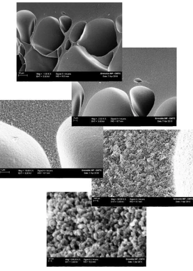
Carbon aerogels are produced by pyrolysis of organic aerogels [Pek 1989, Bri 1990]. Initially, organic aerogels have been obtained by synthesis of organic gels via sol-gel method and subsequent supercritical drying of the gel. Nowadays, however, materials resulting from any drying process of a gel synthesized by any method may be called aerogel, if the organic gel’s structure is maintained throughout the drying process. The carbon aerogel, resulting from gel synthesis, gel drying, and pyrolysis of the organic aerogel, is a three-dimensional network of interconnected manometer-sized and usually colloidal-like carbon particles. Carbon aerogels have been synthesized based on various precursors such as resorcinol-formaldehyde (RF), phenol-resorcinol-formaldehyde, phenolic-furfural, melamine-formaldehyde, polyurethanes, and polyureas [Pek 1998]. A carbon aerogel’s structure and other characteristics depend naturally on the organic precursor, the drying method, and the pyrolysis process. The chemistry and the structure of the organic precursor, which in this case is the organic aerogel (OA) have an influence on the resulting carbon aerogel. Conveniently, the OA structure depends on the synthesis conditions, i.e. on the sol-gel synthesis parameters. An OAs structure can, therefore, be tailored by adapting synthesis conditions (e.g. by precursor ratios and drying method). Characteristics such as density, mean pore size and mean pore size distribution, specific surface area, and particle size can be tuned [Sch 1995, LuC 1995]. Also, particle size and pore size can be changed independently by the variation of sol-gel synthesis parameters [Mar 2009], for example by varying the pH of RF-based gels (see figure I-7). In addition, micropores and mesopores have different origins and can thus be tailored independently. While micropores in aerogels are related to the intra-particle structure, meso- and macropores depend on the inter-particle structure [Mor 2005].
30
Figure I-7:Morphology of RF-based carbon xerogels prepared at various pH a) pH 6.50, b) pH 6.00, c) pH 4.00 [Job 2009]
Resorcinol-formaldehyde based carbon aerogels, which are the most widely known type of carbon aerogels, display high porous volumes and surface areas (up to 1100 m2/g), uniform mesopores sizes, and high electrical conductivity (25-100 S/cm), i.e. low electrical resistivity [Pan 2006, Lee 2010, LiW 2008]. Further, they can be produced as monoliths, composites, thin films, etc. As for any other carbon material, a CA’s surface and porosity can additionally still be augmented by activation.
2.2.3. Carbon Blacks (CB)
Carbon blacks are commercially available and economically viable carbon materials (with a production of roughly 8 million tons per year [Mor 2006]) in the form of carbon spheres and their aggregates of colloidal size (i.e. with sizes below 1000 nm). Carbon blacks are fabricated by thermal decomposition or partial combustion usually of gaseous hydrocarbons (such as gases, oils, or distillates) [Fit 1995, Pan 2006]. Typically, carbon blacks are characterized by small carbon particle and also aggregate sizes, relatively high porosity, high conductivity, and a chemically clean oxygen free surface. Specific surface areas can be as low as 10 m2/g, but are usually around 100 – 150 m2/g and may become as high as 1500 m2/g upon thermal activation [Pan 2006]. CB’s of high surface areas (> 500 m2/g) contain of a high quantity of interparticle meso- and micropores. These are interparticle pores of small carbon particles (10-15 nm), which by covalent linking make up aggregates, which, in return, agglomerate by van der Waals forces (see figure I-8) [Mor 2006, Mar 2009].
31
Figure I-8: Carbon black microstructure (based on [Mor 2006])
Evidently, the porous properties of carbon blacks are governed by the carbon aggregates and their agglomeration. As the formation of aggregates and their subsequent agglomeration can hardly be controlled, particle sizes (i.e. specific surface area) and porous properties are closely linked.
2.2.4. Carbon Nanostructures (CN) – Carbon Nanotubes (CNTs)
Carbon nanostructures (e.g. carbon nanotubes, nano-fibers, fullerenes, etc.) are produced by catalytic decomposition of a selection of hydrocarbons or by high temperature processes aimed at vaporizing a certain carbon composite. The type of nanostructure (e.g. nanotubes, buckyballs, nanohorns, nanobuds, etc.) and corresponding characteristics can be controlled by the choice of precursor and production parameters. However, some types of carbon nanostructures (such as the different fullerenes, e.g. the buckminster-fullerene C60) are used to design a specific molecular form
of carbon only, while others (e.g. carbon nanotubes) are used to design a whole group of different molecular forms and compounds. Carbon nanotubes (CNTs), for example, are usually produced by catalytic decomposition of hydrocarbons on small metal particles (see figure I-9), but may also be produced by electric arc growth [ViD 2001] and plasma processes [Oku 2004, Mor 2006]. Their compounds feature high accessible porosities (typically made up of mesopores), low electrical resistance, high thermal conductivity, and high mechanical strength, depending on the molecular form of the nanotube. Porosities in carbon nanostructures are commonly based on interstitial spaces in the entangled nanostructure network and therefore easily accessible. Due to the nature of the specific surface in carbon nanostructures, surface areas are limited, but may be increased by activation [Pan 2006].
32
Figure I-9:TEM images of carbon nanotubes obtained over Fe,Co/zeolite catalyst aligned into bundle-like structure [Her 2004]
2.2.5. Templated Carbons (TC)
Templated carbons are strictly speaking not a type of carbon material, but rather different carbon materials engineered to be porous by using the template method. In the template method, a gaseous or liquid carbon-rich precursor is introduced into the pores of a template (such as ordered silica, or zeolites). After introduction of the precursor inside the template, the template/precursor composite is heat-treated and the carbon-rich precursor, therefore, pyrolyzed. Subsequently, the template is removed from the composite by acid treatment (usually in hydrofluoric acid). The carbon remaining after acid treatment is thus the negative replica of the template (see figure I-10) [Joo 2001, Vix 2004, InK 2004, Vix 2005, Fra 2007, Ina 2009].
Figure I-10: Schematic illustration of the formation of a templated carbon (based on [Ina 2009])
The structure of the template carbon depends on the template and type of precursor. Different templates of different structures and porous characteristics have been investigated, particularly meso- and microstructured silica (see figure I-11) [Joo 2001, Vix 2004, Vix 2005, Fra 2007, Ina 2009] and zeolites [InK 2004, Ina 2009]. The carbon-rich precursor may either be a liquid or a gas and the
33 template carbon synthesis is carried out either via liquid impregnation (e.g. of a sucrose solution, pitch, furfuryl alcohol) or by chemical vapor infiltration (e.g. of propylene) or introduction through vapor (e.g. acrylonitrile) [Joo 2001, Vix 2004, InK 2004, Vix 2005, Fra 2007].
Figure I-11: TEM image of a template carbon using silica as template and pitch as carbon source [Vix 2005]
General characteristics of template carbons include that their structure in terms of pore sizes, pore size distributions, pore shapes, and interconnectivity of pores may be perfectly controlled. The micro- and mesoporosity may be varied by using different templates, precursor types and precursor quantity [Gad 2005]. Templated carbons can display very high microporous volumes and surface areas, depending on the template used. Surface areas and micropore volumes of up to 4000 m2/g and 1.8 cm3/g respectively have been reported for the use of a zeolite template [Ina 2009]. Nonetheless, the template method also has some disadvantages mainly due to the complicated carbon preparation process for example generating high costs and the use of oftentimes toxic and/or corrosive acids for the template dissolution. Also, for the time being, only a limited choice of template structures has been investigated, although research on templates continues (such as metal oxide templates MgO and NiO) [Ina 2009]. Therefore, an industrial production of templated carbones has not been envisioned.
Additional porosity, i.e. porosity not induced by the template, may be created by using specific carbon-rich precursors. At using a sucrose aqueous solution as precursor, for example, the formation of additional microporosity has been observed (due to the elimination of water and to the extensive thermal decomposition of sucrose) [Vix 2005]. Therefore, it has to be taken into account, that depending on the carbon-rich precursor, the final template carbon’s structure may or may not be the exact negative replica of the template.
2.2.6. Further Processes for synthesizing Nanostructured Carbon Material
Still other methods also allow engineering porous carbons; amongst them defluorination of polytetrafluoroethylene, polymer blend process, and selection of specific precursors.
34
2.2.6.1. Defluorinatio n of Polytetrafluoro ethylene
Porous carbons may be produced by defluorinating polytetrafluoroethylene PTFE with alkali compounds (such as lithium fluoride, sodium, potassium, and rubidium) at elevated temperatures and sometimes pressures and subsequent washing (to remove excess alkali metals) and carbonization. The resulting carbons structure depends chiefly on the alkali metal used for defluorination. Using this method, porous carbons with specific surface areas as high as 2225 m2/g can be generated. However, this process is quite expensive due to the precursors and the treatment of the oftentimes toxic and/or corrosive by-products [InK 2004, Ina 2009].
2.2.6.2. Polymer Blend Process
In the polymer blend process, two different types of polymers are mixed. One of the polymers is supposed to have a high carbon yield upon carbonization (such as phenol-formaldehyde resin or polyacrylonitrile), while the second polymer is wanted to have a low carbon yield if pyrolyzed (such as polyethylene or polymethylmethacrylate). Generally the precursor yielding much carbon (also called carbon precursor polymer) is enveloped by the precursor yielding less carbon (also called pore former polymer), as can be seen schematically in figure I-12. In the course of the pyrolysis, the pore forming polymer in the polymer composite’s core is gasified nearly completely. In the meantime, the carbon precursor polymer results in a solid carbon material enveloping the porous spaces created by the pyrolysis of the pore forming polymer [InK 2004, Ina 2009]. Thus, pore-containing carbons may be generated by using the polymer blend process.
Figure I-12: Polymer blend process used for producing a) carbon tube containing thin carbon fibers b) multi-walled carbon tube [InK 2004]
2.2.6.3. Selection of spec ific Precursors
One of the simplest methods of producing porous carbon material is the choice of specific organic precursors which give porous carbons upon pyrolysis. Such specific precursors may be polyimides, metal carbides, biomass products, etc. In the case of carbon based on polyimide precursors, for
35 example, the polyimide’s structure is retained throughout carbonization. As for biomasses, for example, carbonization of the kenaf plant without any kind of activation treatment involved, leads to carbons with specific surface areas as high as 2700 m2/g [InK 2004, InN 2004, Ina 2009]. Nonetheless, this method of creating porous carbons is hardly flexible; porosity characteristics cannot be adjusted. In addition, carbon characteristics, costs, and availability depend obviously foremost on the organic precursor.
2.3.Nanostructured Carbon Material derived from Biomass
As seen above, nanostructured, porous carbons can be synthesized from manifold precursors through a variety of methods. Most combinations of precursors and synthesis methods resulting in porous carbon material, however, do not include biomass-based carbons. Nonetheless, some methods may employ biomass or biomass derivatives to produce nanostructured carbons, such as the selection of specific precursors, activation, or carbon aerogel synthesis.
2.3.1. Pyrolysis of specif ic biomass-based Precursors
By selection of specific biomass-based precursors and corresponding carbonization conditions, nanostructured carbons can be produced. Carbonizing biomass, like other non-graphitizing carbons, can result in the creation of porous carbons, due to the retention of a rigid and complex molecular structure in addition to a loss of volatile matter during pyrolysis [Pan 2006]. Carbons resulting from the pyrolysis of biomass products such as coconut shells and wood chips may possess high macroporous volumes, due to the memory of the original biomass’ cell structure. Carbonization of organic material like the cores of the kenaf plant or sucrose solutions may even lead to microporous carbons with high specific surface areas [InK 2004, InN 2004, Vix 2005]. This porosity seems to be created by the elimination of metallic impurities or of water combined with an extensive thermal decomposition, for the cores of kenaf plants [InN 2004] and sucrose solutions [Vix 2005], respectively. The cost for these biomass precursors is variable, but oftentimes still economical. The availability of large amounts of certain precursors, on the other hand, might be difficult. A still larger drawback of choosing this method in order to synthesize nanostructured, porous carbons, is that porous characteristics (i.e. pore sizes and pore size distributions) can hardly be controlled.
An attempt to control porous characteristics while using specific biomass precursors has been made, for example, using the template method with a sucrose solution [Vix 2005]. Nonetheless, in this case the porous characteristics can also be controlled only partly, i.e. the part of porosity created by dissolving the template. Also, even though the precursor for carbonization may be chosen to be on the basis of biomass for environmental concerns, a harmful acid treatment is still required to separate the carbon from the template.
2.3.2. Biomass-based Activated Carbons
As activation can be used on all types of carbon-rich material to introduce porosity into these, all types of biomass material having undergone pyrolysis can be activated. Activation has been investigated, for example, for fruit stones (e.g. olive, peach, and cherry stones), cellulose fibers (e.g. jute and coconut fibers), wood (e.g. teak sawdust) and other biomass (e.g. almond shells), as well as for other organic waste material (e.g. textile waste) [Rod 1995, Mol 1996, Rod 1992, Oli 2009, Pha
36 2006, Ism 2005, Guo 2003, Pra 2008, Sch 2007, Wil 2006, Tay 2009]. Even for biomass already containing macropores after carbonization, such as coconut shells and wood chips [Ina 2009], activation can be used to introduce microporosity. Although the porous characteristics (i.e. porous volumes and mean pore sizes) can essentially be controlled by the choice of activating agent and the process parameters, the carbon structure cannot (i.e. the carbon forming the pore walls). Also, narrow pore size distributions are difficult to obtain [Loz 2002]. In addition, activating agents for chemical activation are often harmful to the environment and may leave residues.
2.3.3. Biomass-based Carbon Aerogels
As mentioned before, carbon aerogels are obtained from the pyrolysis of organic aerogels. Even though a variety of biomass derivative-based gels have been investigated (e.g. cellulose-, lignin-, or xylane-based [Jin 2004, Aal 2009]), only very few have been synthesized by sol-gel method. Reports on biomass-based or biomass-derivative-based gels synthesized by sol-gel method are usually constricted to gels on the basis of chemically modified cellulose (such as cellulose acetate [Tan 2001, FiR 2006]), with some exceptions such as a recent report on the synthesis of chitin-based organic aerogels [Tsi 2009]. By synthesizing gels via sol-gel method, the gels structure and therefore the aerogels structure can be controlled.
3.
Carbon Aerogels
Aerogels have first been synthesized, studied, and also named by S. Kistler in the 1930s [Kis 1931]. Carbon aerogels, however, have only been developed and studied thoroughly much later by Pekala in the 1980s [Pek 1989].
The preparation of a carbon aerogel consists of three main steps (see figure I-13): i) synthesis of an organic gel by sol-gel method, ii) drying of the wet gel, and iii) carbonization of the aerogel. Drying of the wet gel needs to be carried out in conditions which allow to maintaining the three-dimensional structure and open porosity of the initial gel.
Figure I-13: Schematic illustration of carbon aerogel synthesis
3.1.Gel Synthesis
Aerogels are prepared on the basis of a gel, typically having been synthesized by sol-gel method. A gel is, according to [Pha 2004], a thermodynamically stable solid-liquid biphasic system consisting of two interpenetrated three-dimensional networks: a solid one and a liquid one.
The preparation of gels by sol-gel process can be divided in three main stages: i) preparation of the sol, ii) sol evolution and sol-gel aggregation resulting finally in the transition from sol to gel, and iii)
![Figure I-11: TEM image of a template carbon using silica as template and pitch as carbon source [Vix 2005]](https://thumb-eu.123doks.com/thumbv2/123doknet/3031339.85303/34.892.281.611.203.503/figure-image-template-carbon-silica-template-carbon-source.webp)