? UNIVERSITÉ DE
SHERBROOKE
Faculté de génie
Département de génie chimique
EFFECT OF DIFFERENT CARBON BLACK TYPES ON SINGLE-WALLED CARBON
NANOTUBE PRODUCTION BY INDUCTION THERMAL PLASMA
EFFET DES DIFFÉRENTS TYPES DE NOIR DE CARBONE DANS LA SYNTHESE DES NANOTUBES DE CARBONE MONO-PAROI EN UTILISANT LE PLASMA THERMIQUE
INDUCTIF
Maîtrise es sciences appliquées
Spécialisation : Génie chimique
Composition du jury
Peter Jones Rapporteur
X. Grant Chen Correcteur
Gervais Soucy
Directeur de mémoire
Yasaman ALINEJAD
Sherbrooke, (Québec), CANADA Mai 2008
?F?
CanadaLibrary and Archives
Published Heritage Branch 395 Wellington Street Ottawa ON K1A 0N4 Canada Bibliothèque et Archives Canada Direction du Patrimoine de l'édition 395, rue Wellington OttawaONK1A0N4 CanadaYour file Votre référence
ISBN: 978-0-494-65608-2
Our file Notre référence
ISBN: 978-0-494-65608-2
NOTICE:
The author has granted a
non-exclusive license allowing Library and
Archives Canada to reproduce,
publish, archive, preserve, conserve,
communicate to the public by
telecommunication or on the Internet,
loan, distribute and sell theses
worldwide, for commercial or
non-commercial purposes, in microform,
paper, electronic and/or any other
formats.
The author retains copyright
ownership and moral rights in this
thesis. Neither the thesis nor
substantial extracts from it may be
printed or otherwise reproduced
without the author's permission.
In compliance with the Canadian
Privacy Act some supporting forms
may have been removed from this
thesis.
While these forms may be included
in the document page count, their
removal does not represent any loss
of content from the thesis.
AVIS:
L'auteur a accordé une licence non exclusive
permettant à la Bibliothèque et Archives
Canada de reproduire, publier, archiver,
sauvegarder, conserver, transmettre au public
par télécommunication ou par l'Internet, prêter,
distribuer et vendre des thèses partout dans le
monde, à des fins commerciales ou autres, sur
support microforme, papier, électronique et/ou
autres formats.
L'auteur conserve la propriété du droit d'auteur
et des droits moraux qui protège cette thèse. Ni
la thèse ni des extraits substantiels de celle-ci
ne doivent être imprimés ou autrement
reproduits sans son autorisation.
Conformément à la loi canadienne sur la
protection de la vie privée, quelques
formulaires secondaires ont été enlevés de
cette thèse.
Bien que ces formulaires aient inclus dans
la pagination, il n'y aura aucun contenu
manquant.
¦+¦
RESUMÉ
Les nanotubes de carbone (CNT) sont les nouvelles formes de matériaux qui ont nombreuse
nouvelles et utiles propriétés. Les nanotubes de carbone mono paroi, (en anglais,
Single-Walled Carbon Nanotubes, SWCNTs) présentent les propriétés électroniques,
mécaniques et chimiques exceptionnelles. Ils sont les meilleurs conducteurs d'électricité et
de chaleur et aussi les plus fortes et les plus rigides des matériaux connus pour l'humanité. Il
existe quatre méthodes couramment utilisées pour synthétiser les nanotubes de carbone: arc
de décharge, le dépôt de. vapeur chimique (en anglais, chemical vapour deposition, CVD),
ablation par laser et ablation par plasma thermique. La technologie des plasmas thermiques
est extraordinairement bien adaptée à la synthèse des nanotubes de carbone en raison de sa
haute température, haute densité d'énergie et abondante contenus des espèces réactives.
Les nanotubes de carbone ont été synthétisés à partir de différentes sources de carbone. L'utilisation future des nanotubes de carbone en grande échelle nécessitent une intervention
rapide, efficace avec les méthodes de synthèse à coût faible, et ne nécessitent pas de
matériau initial coûteux. Le noir de carbone est une source appropriée de carbone pour la
production de nanotubes de carbone en raison de sa disponibilité et le faible coût industriel.
Ce travail aborde la recherche sur la synthèse des nanotubes de carbone mono paroi par la technologie de plasma d'induction utilisant du noir de carbone comme source de carbone.
Les objectifs principaux de cette recherche sont les suivants: 1) Examiner les différentes
types de noir de carbone provenant de différentes entreprises afin de trouver la meilleure
qualité du noir de carbone pour la production des nanotubes de carbone mono paroi et 2)
Étudier les différentes propriétés de noirs de carbone qui affectent la qualité des nanotubes
de carbone mono paroi.
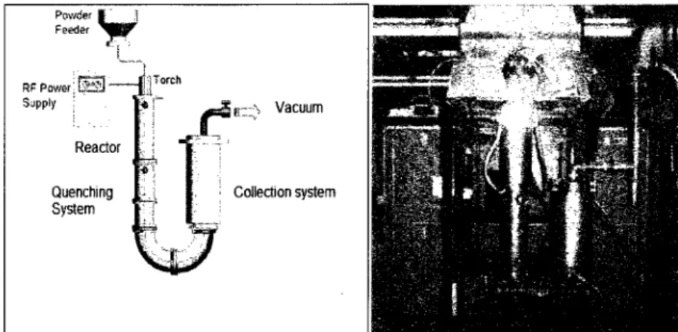
La méthode utilisée est basée sur la vaporisation directe d'un mélange de noir de carbone et
le catalyseur métallique dans le plasma. Le montage expérimental est composé d'un réacteur
à paroi refroidie équipé d'une torche à plasma induit par haute fréquence de 3 MHz.
Une série d'expériences ont été complétée afin d'évaluer les capacités des noirs de carbones
dans la production des nanotubes de carbone mono paroi de haute qualité. Huit catégories
de carbone dans ces expériences. Un mélange ternaire de nickel, de cobalt, et de l'oxyde
d'yttrium a été utilisé comme catalyseur. Différentes propriétés du noir de carbone, tells que
le contenu en soufres, la taille des particules, et le degré de graphitisation ont été étudiés afin
de trouver l'impact qu'ils ont sur la production et la qualité des nanotubes de carbone mono
paroi.
Une série d'expériences ont été complétée pour étudier l'effet de mélange de différents types
sur le comportement de noir de carbone dans la synthèse et aussi sur la qualité du produit.
Tout au long de l'étude, la microscopie électronique à balayage à haute résolution (HRSEM),
l'analyse élémentaire (EDS), la spectroscopie Raman, la diffractométrie de rayons X, et
l'analyse thermique (TGA/DTG) ont été effectuées pour évaluer la qualité du matériel produit.
La diffractométrie de rayons X a été fait pour évaluer les données microstructurales de la
matière initial.Il a été constaté que le noir de carbone avec des propriétés diverses telles que la taille des
particules, le contenu en soufre, et de la taille des grains produira les nanotubes de carbone
mono paroi qui se distinguent par leur différente qualité. En d'autres termes, les différentes
propriétés de noirs de carbone ont des effets directs sur la qualité de SWCNTs. Il a
également été montré que les propriétés de noirs de carbone n'affectent pas la distribution de
la taille des nanotubes de carbone mono paroi et dans les mêmes conditions, en utilisant les
différentes classes de noir de carbone ne va pas changer le diamètre du taille du produit.
Mélanger différents noirs de carbone ne peut pas améliorer la qualité de SWCNTs. Les
produits obtenus lors d'utilisation de tous les mélanges de différents noirs de carbone ont des
mauvaises qualités comparant avec les produits obtenus lorsque les mélanges ne sont pas
utilisés.ABSTRACT
Carbon nanotubes (CNT) are important new class of technological materials that have numerous novel and useful properties. Single-Walled Carbon Nanotubes (SWCNTs) have exceptional electrical, mechanical and chemical properties. They are the best conductors of electricity and heat and the strongest and stiftest materials known to mankind. There are four methods commonly used to synthesize CNTS: arc discharge, chemical vapour deposition (CVD), laser Ablation and thermal plasma technique. Thermal plasma technology is extra-ordinarily well-suited for carbon nanotube synthesis because of its high temperature, high energy density and abundant contents of reactive species.
Carbon nanotubes (CNTs) have been synthesized from different carbon sources. Large scale future uses of carbon nanotubes require a rapid, efficient, low cost method of synthesis, and do not require expensive starting material. Carbon black, due to its industrial availability and low cost, is an appropriate starting carbon source for carbon nanotube production.
The work presented here is focused on the synthesis of SWCNTs by inductively coupled thermal plasma using carbon black as a carbon source. The main objectives of this research are; 1) Examining different grades of carbon black from different companies in order to find the best carbon black grade for SWCNTs production and 2) Studying different properties of carbon blacks which affect the quality of the SWCNTs.
The methodology used in the experimental design is based on the direct evaporation of a mixture of carbon black and metallic catalyst inside the plasma plume. The experimental set-up consisted of a continuous flow type reactor equipped with a high frequency plasma torch operated at 3 MHz.
A serie of experimental tests were conducted to evaluate the ability of carbon blacks in
producing high-quality SWCNTs. Eight grades of carbon blacks from three different
as sulfur content, particle size, and degree of graphitization have been studied in order to find the impact they have on SWCNTs production and quality.
A serie of experimental tests were performed to study the effect of mixing different grades on the behaviour of carbon black in SWCNTs synthesis and the impact of mixing on the quality of the product.
Throughout the study, high resolution scanning electron microscopy (HRSEM), electron dispersive spectroscopy (EDS), and Raman spectroscopy, X-ray diffraction analysis (XRD), and thermo gravimetric analysis (TGA) were performed to evaluate the quality of the produced material. X-ray diffraction analysis was done to evaluate the microstructural data for the starting material.
Overall, it has been found that carbon black grades with various properties such as particle size, sulphur content, and grain size will produce SWCNTs which differ in quality. In other words, different properties of carbon blacks have direct impact on the quality of SWCNTs. It has also been shown that properties of carbon blacks do not affect the size distribution of SWCNTs and under the same conditions, using different grades of carbon black will not change the diameter size of the product.
Mixing different carbon black grades cannot improve the quality of synthesized soot. All the mixtures of different carbon blacks yielded in worse quality products comparing with the product obtained when mixtures were not used. However, it seems that mixing different grades can reduce clogging problems since no clogging interrupted the operation during the experiments in which mixtures were used as a feedstock.
ACKNOWLEDGMENTS
I would like to express my thanks and gratitude to all who have made the completion of this work possible.
I would like to thank my thesis director, Gervais Soucy, for his helpful guidance, advice, patience, and support throughout the fulfillment of this work.
I would like to thank all my colleagues for their valuable guidance and assistance that helped
me so much.
I wish to thank all the members of the IMSI, for their great help in the characterization part of
this work.
I would like to thank all the people who helped me during the experimental part of this work. I want to express all my love and appreciation to my family for their extreme love and support. I would like to thank all the staff of the chemical engineering department especially secretaries for their help and kindness.
CONTENTS RÉSUMÉ i ABSTRACT ili ACKNOWLEDGEMENTS ? CONTENTS vi LISTOFFIGURES ix
LIST OF TABLES xvi
!.INTRODUCTION 1
1.1 Background 1
1 .2 Carbon nanotubes (CNTs) 1
1 .2.1 Special properties of CNTs 2
1.3 Single-walled carbon nanotubes (SWCNTs) 4
1.4 Carbon Source 6
1.5 Objectives of the master project 6
2. LITERATUREREVIEW 7
2.1 Synthesis
7
2.1.1 Arc discharge 7
2.1.2 Laser ablation 11
2.1.3 Chemical vapour deposition 13
2. 1.4 Thermal plasma technique 14
2.2 Carbon Black 20
2.2.1 Background 20
2.2.2 Microstructure 21
2.2.4 Characteristics of carbon blacks 25
2.3 Carbon Black as a carbon source for CNT production 26
2.4 Properties of carbon black that can affect SWCNT production
31
2.4.1 Degree of graph itization 31
2.4.2 Particle size 33
2.4.3 Sulfur content 33
3. EXPERIMENTAL PROCEDURES, MATERIALS, AND CHARACTERIZATION
TECHNIQUES 36
3.1 Experimental Set-Up 36
3.1.1 Mass and energy balance 40
3.2 Materials 42 3.2.1 Carbon source 42 3.2.2 Catalyst 43 3.2.3 Plasma gases 44 3.3 Operating conditions 45 3.4 Characterization techniques 46 3.4.1 Raman Spectroscopy 46
3.4.2 Thermo-gravimetric analysis (TGA) 49
3.4.3 High resolution scanning electron microscopy (HRSEM)
50
3.4.4 X-ray diffraction (XRD) 51
3.4.5 Energy Dispersive x-ray Spectrometer (EDS)
51
3.5 Sample preparation procedure for characterization 53
3.5.2 Thermo-gravimetric Analysis (TGA)
54
3.5.3 Raman spectroscopy 54
3.5.4 X-ray diffraction (XRD) 54
4. THERMODYNAMIC STUDY 56
4.1 Thermodynamic study of the SWCNT formation 57
4.2 Reacting system at chemical equilibrium 57
5. RESULTS AND DISCUSSION 67
5.1 Microstructural properties of different carbon blacks 67 5.2 Different grades of carbon blacks used in SWCNTs synthesis by induction
thermal plasma 74
5.2.1 Experiments with carbon blacks from Columbian Co 74
5.2.2 Experiments with carbon blacks from Cabot Co 94
5.2.3 Experiment with carbon black from Timcal Co 116
5.3 Comparison of the results 122
5.4 Effect of mixing on the carbon black behaviour in SWCNTs production 127
5.4.1 Mixture of Raven 860 ultra and M-880 127
5.4.2 Mixture of Raven 860 ultra and Elftex-12 130
5.4.3 Mixture of Raven 860 ultra and Super P 134
CONCLUSION 138
LIST OF FIGURES
Figure 1.1 Chiral vectors in a graphene sheet 4
Figure 1 .2 Some SWCNTs with different chiralities
5
Figure 2.1 Experimental set-up of an arc discharge apparatus 8
Figure 2.2 The apparatus used for CNT formation
9
Figure 2.3 Schematic diagram of an arc-jet plasma reactor for CNT synthesis by
decomposition OfCH4
10
Figure 2.4 Schematic drawings of a laser ablation apparatus 12
Figure 2.5 A scheme of the thermal plasma system for the continuous production of CNTs
without introducing of catalyst sources, by placing graphite plate inside the
flame 14
Figure 2.6 Scheme of the thermal plasma system for the continuous production of CNTs. ...16
Figure 2.7 The proposed mechanism for the growth of different diameter CNTs in the thermal
plasma jet system 17
Figure 2.8 Experimental apparatus for nanoparticle preparation 19 Figure 2.9OiI furnace reactor used for carbon black production 21
Figure 2.10 (a) TEM ¡mage of carbon black particles and random crystallite Orientation in
carbon black and (b) TEM image of graphite sheet and typical crystallite showing
turbostratic structure 22
Figure 2.1 1 SEM image of (a) agglomorates and (b) aggregates of a carbon black powder..23
Figure 2.12 Shape categories for carbon black aggregates
24
Figure 2. 1 3 Shape categories for carbon black aggregates
24
Figure 2.14 Surface of carbon black slug after 10 s of synthesis: (a) low magnification SEM
micrograph showing island structure and (b) high magnification SEM micrograph of
initial nanotube formation 27
Figure 2.15 Typical high-resolution TEM ¡mages of carbon black, DWCNTs grown from
catalysts and DWCNTs. (a) Carbon black as the dot carbon source and (b) a single
DWCNT grown from a small catalyst particle and small DWCNT bundles grown
from a large one 28
Figure 2.16 Typical XRD diagram of carbon black powder
31
Figure 2.17 Micro structural of a carbon black 32
Figure 2.18 TEM images of (a) straight CNTs continuously filled with catalyst particles; (b) L
carbon nanotube junction; (c) Y branched carbon nanotube 35 Figure 3.1 Experimental setup of the production process for carbon nanostructures 36
Figure 3.2 RF inductively coupled plasma torch 37
Figure 3.3 A single-screw powder feeder used to feed the raw material during the
Operations 38
Figure 3.4 Scheme of the head-box of the powder feeder (a) the old design and (b) the new
design 39
Figure 3.5 RF injection zones of plasma gasses in a RF plasma torch
45
Figure 3.6 Raman spectrum showing the most characteristic features of CNTs: radial
breathing mode (RBM), the D-band, G-band and G'-band
47
Figure 3.7 A typical TGA profile of as-prepared SWCNTs synthesized by induction thermal
plasma 50
Figure 3.8 Image of a round shape particle found during EDS analysis taken by secondary
electron beam with (a) low detector and (b) mix detector 52
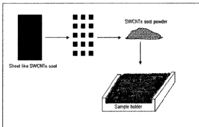
Figure 3.9 (a) the sheet like product collected from the collection chamber that contains (b)
Figure 3.10 Schematic procedure used to prepare samples from sheet-like soot for XRD
analysis 55
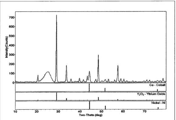
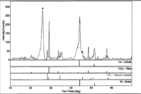
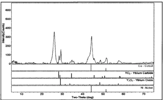
Figure 4.1 XRD pattern of raw SWCNTs soot produced by induction thermal plasma
process 60
Figure 4.2 TGA/DGT graph of soot containing SWCNTs produced by induction thermal
plasma process 62
Figure
4.3
Thermodynamic
equilibrium
compositions
of
mixture
system
of
1C+0.006Ni+0.006Co+0.004 Y2O3+0.00075S+1Ar+5He at 500 Torr 64
Figure
4.4
Thermodynamic
equilibrium
compositions
of
mixture
system
of
1C+0.006Ni+0.006Co+0.004Y2O3+0.004S+1Ar+5Heat500Torr 65
Figure
4.5
Thermodynamic
equilibrium
compositions
of
mixture
system
of
lC+0.006Ni+0.006Co+0.004Y2O3+0.008S+1Ar+5Heat500Torr 66Figure 5.1 XRD diagrams of the four grades of carbon black from Cabot Company
67
Figure 5.2 XRD patterns for three grades of carbon black from Columbian Co
68
Figure 5.3 XRD pattern of carbon black a) M-880, b) M-120, c) M-280, d) Elftex-12, e) Raven
430 ultra, f) Raven 450, g) Raven 860 ultra, and h) Super P 69-72
Figure 5.4 Raman spectrum of SWCNTs containing soot produced with Raven 450 CB
75
Figure 5.5 Radial breathing mode of Raman spectrum of SWCNTs containing soot produced
with Raven 450 CB 75
Figure 5.6 HRSEM image of SWCNT containing soot produced with Raven 450 CB
76
Figure 5.7 EDS analysis for as-produced soot using Raven 450 as a carbon source 76
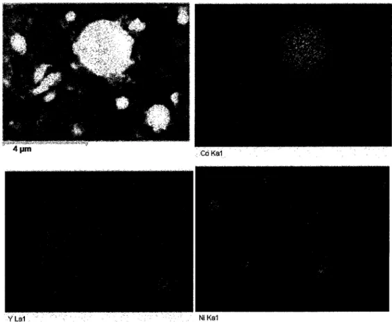
Figure 5.8 Mapping analysis of as-produced soot using Raven 450 as a carbon source
77
Figure 5.9 Mapping analysis of a catalyst particle in the sample of as-produced soot using
Raven 450 as a carbon source 78
Figure 5.10 HRSEM image of (a) carbon black shape material produced in synthesis of
Figure 5.11 HRSEM ¡mage of sheet-like soot which is composed of many layers 79
Figure 5.12 (a) Surface of the sample before removing one layer and (b) after removing one
layer 79
Figure 5.13 XRD pattern of the feedstock containing Ni, Co, Yttrium oxide and carbon
black 81
Figure 5.14 XRD pattern of the soot containing SWCNT produced by using Raven 450 CB as
a carbon source 82
Figure 5.15 TGA/DTG graph of SWCNT soot produced by using Raven 450 CB as a carbon
source 83
Figure 5.16 TGA/DTG graph of the feedstock used to produce SWCNT product by induction
thermal plasma process 84
Figure 5.17 Raman spectrum of SWCNTs containing soot produced with Raven 860 ultra
CB 86
Figure 5.18 Radial breathing mode of Raman spectrum of SWCNTs containing Soot
produced with Raven 860 ultra CB 86
Figure 5.19 HRSEM image of SWCNT containing soot produced with Raven 860 ultra
CB 87
Figure 5.20 EDS analysis for as-produced soot using Raven 860 ultra as a carbon
Source 87
Figure 5.21 XRD pattern of the soot containing SWCNT produced by using Raven 860 ultra
CB as a carbon source 88
Figure 5.22 TGA/DTG graph of SWCNT soot produced by using Raven 860 ultra CB as a
carbon source 89
Figure 5.23 Raman spectrum of SWCNTs containing soot produced with Raven 430 ultra
CB 90
Figure 5.24 Radial breathing mode of Raman spectrum of SWCNTs containing soot produced
Figure 5.25 HR SEM image of SWCNT containing soot produced with Raven 430 ultra
CB 91
Figure 5.26 EDS analysis for as-produced soot using Raven 430 ultra as a carbon
Source 91
Figure 5.27 Mapping analysis of a catalyst particle in the sample of as-produced soot using
Raven 430 ultra CB as a carbon source 92
Figure 5.28 (a) HRSEM images of untreated catalyst particle and (b) mapping ¡mage of
untreated yttrium particle 92
Figure 5.29 XRD pattern of the soot containing SWCNT produced by using Raven 430 ultra
CB as a carbon source 93
Figure 5.30 TGA/DTG graph of SWCNT soot produced by using Raven 430 CB as a carbon
source 94
Figure 5.31 Raman spectrum of SWCNTs containing soot produced with M-880 CB
95
Figure 5.32 Radial breathing mode of Raman spectrum of SWCNTs containing soot produced
with M-880 CB 95
Figure 5.33 HRSEM image of SWCNT containing soot produced with M-880 CB
96
Figure 5.34 EDS analysis for as-produced soot using M-880 CB as a carbon source
96
Figure 5.35 XRD pattern of the soot containing SWCNT produced by using M-880 CB as a
carbon source 97
Figure 5.36 DTG graph of SWCNT soot produced by using M-880 CB as a carbon
Source 98
Figure 5.37 Raman spectrum of SWCNTs containing soot produced with M-280 CB
99
Figure 5.38 Radial breathing mode of Raman spectrum of SWCNTs containing soot produced
with M-280 CB 99
Figure 5.39 HRSEM image of SWCNT containing soot produced with M-280 CB
100
Figure 5.41 HRSEM ¡mage of a yttrium particle found in the as-produced soot from the
filter 101
Figure 5.42 Mapping analysis of the big particle found in the as-produced soot
101
Figure 5.43 High magnification HRSEM image of SWCNT containing soot produced with
M-280 CB 102
Figure 5.44 XRD pattern of the soot containing SWCNT produced by using CB M-280 as a
carbon source 102
Figure 5.45 DTG graph of SWCNT soot produced by using M-280 carbon black as a carbon
source 103
Figure 5.46 Raman spectrum of SWCNTs containing soot produced with M-120 CB
105
Figure 5.47 Radial breathing mode of Raman spectrum of SWCNTs containing Soot
produced with M-120 CB 105
Figure 5.48 Low magnification HRSEM image of SWCNT containing soot produced with
M-120 CB 106
Figure 5.49 High magnification HRSEM image of SWCNT containing soot produced with
M-120 CB 106
Figure 5.50 EDS analysis for as-produced soot using M-120 CB as a carbon source
107
Figure 5.51 XRD pattern of the soot containing SWCNT produced by using M-120 CB as a
carbon source 107
Figure 5.52 XRD patterns of (a) pure graphite (b) SWCNT soot produced by thermal plasma
process by using M-120 CB as a carbon source (c) M-120 CB
108
Figure 5.53 DTG graph of SWCNT soot produced by using M-120 carbon black as a carbon
source 109
Figure 5.54 Raman spectrum of SWCNT containing soot produced with Elfte-12 CB
110
Figure 5.55 Radial breathing mode of Raman spectrum of SWCNTs containing soot produced
Figure 5.56 HRSEM ¡mage of SWCNT containing soot produced by Elftex-1 2 CB
111
Figure 5.57 EDS analysis for as-produced soot using Elftex-12 CB as a carbon Source 112
Figure 5.58 Mapping analysis of as-produced soot 113
Figure 5.59 XRD pattern of the soot containing SWCNT produced by using M-880 CB as a
carbon source 114
Figure 5.60 DTG graph of SWCNT soot produced by using Elftex-12 CB as a carbon
Source 115
Figure 5.61 Raman spectrum of SWCNTs containing soot produced with Super P CB 116 Figure 5.62 Radial breathing mode of Raman spectrum of SWCNTs containing soot produced
with Super P CB 117
Figure 5.63 HRSEM image of SWCNT containing soot produced by Super PCB 117 Figure 5.64 EDS analysis for the soot produced with Super P CB 118 Figure 5.65 XRD pattern of the soot containing SWCNT produced by using Super P carbon
black as a carbon source 118
Figure 5.66 TGA/DTG graph of as-produced SWCNT soot using Super P carbon black as a
carbon source 119
Figure 5.67 G/D ration vs. grain size for eight carbon black grades 122 Figure 5.68 G/D ration vs. particle size for eight carbon black grades 124 Figure 5.69 G/D ration vs. sulfur content for eight carbon black grades 1 25 Figure 5.70 HR SEM image of SWCNT containing soot produced with mixture of Raven 860
ultra and M-880 127
Figure 5.71 EDS analysis of SWCNT containing soot produced with mixture of Raven 860
ultra and M-880 128
Figure 5.72 Raman Spectra of the as-produced soot using Raven 860 ultra, M-880, and
Figure 5.73 XRD pattern of the soot containing SWCNT produced by a mixture of Raven 860
and M-880 carbon black as a carbon source 129
Figure 5.74 TGA/DTG graph of the SWCNT soot synthesized with a mixture of Raven 860
ultra and M-880 carbon black as a carbon source 130
Figure 5.75 HRSEM image of SWCNT containing soot produced with mixture of Raven 860
ultra and Elftex- 12 131
Figure 5.76 EDS analysis of SWCNT containing soot produced with mixture of Raven 860
ultra and Elftex- 12 131
Figure 5.77 HRSEM ¡mage of SWCNT containing soot produced with mixture of Raven 860
ultra and Elftex- 12 132
Figure 5.78 Raman Spectra of the as-produced soot using Raven 860 ultra, M-880, and
mixture of Raven 860 ultra and Elftex-12 132
Figure 5.79 XRD pattern of the soot containing SWCNT produced by a mixture of Raven 860
and Elftex-1 2 carbon black as a carbon source 1 33
Figure 5.80 TGA/DTG graph of the SWCNT soot synthesized with a mixture of Raven 860
ultra and Elftex-12 carbon black as a carbon source 134
Figure 5.81 HRSEM image of the as-produced soot using mixture of Raven 860 ultra and
Super P, obtained from the filters 134
Figure 5.82 EDS analysis of SWCNT containing soot produced with mixture of Raven 860
ultra and Super P 135
Figure 5.83 Raman Spectra of the as-produced soot using Raven 860 ultra, Super P and
mixture of Raven 860 ultra and Super P 135
Figure 5.84 XRD pattern of the soot containing SWCNT produced by a mixture of Raven 860
and Super P carbon black as a carbon source 136
Figure 5.85 TGA/DTG graph of the SWCNT soot synthesized with a mixture of Raven 860 ultra and Super P carbon black as a carbon source 137
LIST OF TABLES
Table 2.1 Electrode material characteristics 29
Table 3.1 Energy balance of the induction thermal plasma SWCNT synthesis system
41
Table 3.2 Properties of carbon blacks 43
Table 3.3 Properties of catalyst powders 43
Table 3.4 Operating conditions 46
Table 5. 1 Microstructural properties of carbon blacks 73
!.INTRODUCTION
1.1 Background
Carbon nanotubes (CNT) are an important new group of technological materials that have numerous novel and useful properties. There are four methods that are usually used to synthesize CNTs: arc discharge, chemical vapour deposition (CVD), laser ablation and thermal plasma technique. The common feature of these methods is the addition of energy to a carbon source to produce fragments (groups or single C atoms) that can generate CNT. The energy sources utilised may be electricity from an arc discharge, heat from a furnace (~ 900"C) for CVD, the high-intensity light from a laser (laser ablation), or a plasma for thermal plasma technique. The three main types of CNTs are single-walled carbon nanotube (SWCNT), double-walled carbon nanotube (DWCNT), and multi-walled carbon nanotube (MWCNT). Adapted from [DONALDSON et at. 2006]
SWCNTs have exceptional electrical, mechanical and chemical properties. They are the best conductors of electricity and heat and the strongest and stiftest materials known to
mankind.
This present research group has been working on large scale production of SWCNT. According to the specific properties of radio frequency (RF) inductively coupled plasma, such as very high temperatures and a very large plasma volume compared with the DC and micro wave (MW) plasmas, which favours SWCNTs production, RF plasma as a heat source is being used in the system.
1.2 Carbon nanotubes (CNTs)
A year after the discovery of the fullerene bulk production (KRATSCHMER et at. 1 990), lijima first observed tubular carbon structures in 1991 . The method used for the production of these structures was an arc-discharge evaporation technique, being similar to that used in the synthesis of fullerene. These tubular structures, referred to as multi-walled carbon nanotubes (MWCNT), consisted of coaxial tubes of graphite sheets, being of up to 1 µ?? in length and 4 to 30 nm in diameter. [BADDOUR et at. 2005]
Since their initial discovery by lijima, carbon nanotubes have continued to be investigated by many researchers from all over the world. CNTs are, in fact, very large carbon
macromolecules which could be considered as derivatives of both carbon fibres and
fullerenes. Their name is derived from their size range, since the diameter of a nanotube is on the order of a few nanometers, while their length can be up to several micrometers.
They have outstanding chemical, physical and mechanical properties that make them potentially useful in a wide variety of applications in nanotechnology, electronics, optics, and many other fields of materials science. They show extraordinary strength and unique electrical properties, and are efficient conductors of heat. In particular, the geometry of CNTs, their high chemical stability and high mechanical strength are useful in field emitters. Their tubular features induce electric field enhancement at the tips of the tubes, while the orbitals of the graphite structures allow effective electron transport along the tubes. CNT alignment is particularly important in the fabrication of cold-cathode flat panel displays. [SHIRAI et at. 2005]
There are three main types of carbon nanotubes: • Single-walled carbon nanotubes.
• Double-walled carbon nanotubes. • Multi-walled carbon nanotubes.
1 .2.1 Special properties of CNTs
Electrical, molecular and structural properties of carbon nanotubes are determined to a large extent by their nearly one dimensional structure. The chemistry of pure CNTs are surprisingly interesting, i.e. they are significantly unreactive; e.g., SWCNTs must be heated to 500° C before they burn in air. However, there are points in the structure of CNT that are more reactive than others, such as the defects due to missing carbon atoms and the more strained curved-end caps. Smaller nanotubes are more "strained" because they deviate further from the ideal planar structure of graphite. [DONALDSON et at. 2006] The most important properties of CNTs and their molecular background are stated below:
a) Chemical reactivity: The chemical reactivity of a CNT is, in comparison with a graphene sheet, enhanced as a direct result of the curvature of the CNT surface. Carbon nanotube reactivity is directly related to the pi-orbital mismatch caused by the increased curvature. Therefore, a distinction must be made between the sidewall and the end caps of a nanotube. For the same reason, a smaller nanotube diameter results in increased reactivity. Covalent chemical modification of either sidewalls or end caps has been shown to be possible. For example, it is possible to control the solubility of CNTs in different solvents this way. [DAENEN et at. 2003]
electronic devices. Depending on their structure, CNTs can be almost perfect one-dimensional conductors in which various phenomena have been observed at low temperatures:
• Single electron charging
• Resonant tunnelling through discrete energy levels • Proximity-induced superconductivity
At higher temperatures, CNTs behave as a one-dimensional Luttinger liquid. (A liquid where the energy state of its electrons is strongly affected by weak Coulomb interactions)
Since the electrical properties of CNTs are dependent on the tube structure, CNTs can be used as junctions between metal-semiconductor, semiconductor-semiconductor and metal-metal. There are three types of CNT junctions which can be achieved: on-tube, Y and crossed junctions. An on-tube junction can be achieved by joining two tubes of different chirality [Dunlap, 1992] or by chemical doping nanotube segments [ZHOU et at. 2000]
Y and crossed junctions are constructed from Y-branched CNTs [PAPAPDOPULOS et at. 2000] and crossed CNTs [FUHRER et at. 2000]. These various CNT junctions can be used in the construction of parts for nano-scale devices. [BADDOUR et at. 2005]
c) Optical activity: Theoretical studies have shown that the optical activity of chiral nanotubes disappears if the nanotubes become larger. Therefore, it is also to be expected that other physical properties are influenced by these parameters too. Use of the optical activity might result in optical devices in which CNTs play an important role. [DAENEN et at. 2003]
d) Mechanical strength: Carbon nanotubes have a very large Young modulus values in their axial direction. The nanotube as a whole is also very flexible because of its great length. Therefore, these compounds are potentially suitable for applications in composite materials that need anisotropic properties. [DAENEN et at. 2003]
e) Thermal properties: Phonons are used to determine the specific heat and thermal conductivity of CNTs. According to many reports, there is a linear dependence of the
specific heat and the thermal conductivity on temperature. It has also been found that CNTs have high thermal conductivities comparable to those of diamond crystal and in-plane graphite sheet. [BADDOUR et at. 2005]
1.3 Single-walled carbon nanotubes (SWCNTs)
Single-walled carbon nanotubes (SWCNTs) were discovered in 1993 by lijima. They can be considered as elongated and wrapped graphene sheets. Nanotubes generally have a length to diameter ratio of about 1000; thus they can be considered as nearly one-dimensional structures. [DAENEN et at. 2003]. They have exceptional adsorbance capacity, photo physical and chemical behaviours. SWCNTs with length up to orders of centimetres have been produced [ZHU et at. 2002].The Structure of a SWCNT can be conceptualized by wrapping a one-atom-thick layer of graphite called graphene into a seamless cylinder. The way the graphene sheet is wrapped is represented by a pair of indices (n, m) called the chiral vector. The integers ? and m denote the number of unit vectors along two directions in the honeycomb crystal lattice of grapheme. If m=0, the nanotubes are called "Zigzag", If n=m, the nanotubes are known as "armchair". Otherwise, they are called "chiral".
._¦¦ !«.r,1..
C* ß? ttttl '* I
Figure 1 .1 The (n,m) nanotube naming scheme can be thought of as a vector (Ch) in an infinite graphene sheet that describes how to 'roll up' the graphene sheet to make the nanotube. T denotes the tube axis, and a-\ and a2 are the unit vectors for graphene in real space. From [Wikipedia, the electronic
>:ä!
IPl
tel
Figure 1 .2 Some SWCNTs with different chiralities. The difference in structure is easily shown at the open end of the tubes, (a) Arm chair structure (b) zigzag structure (c) Chiral structure. From [KRAMER et at. 2005]
In more detailed version, a SWCNT consists of two separate regions with different physical and chemical properties. The first is the sidewall of the tube and the second is the end cap of the tube. The end cap structure is similar to or derived from a smaller fullerene, such as C60 . [DAENEN et at. 2003]
Structurally distinct single-walled carbon nanotubes (SWCNTs) develop when the graphene sheet is cylindrically rolled along the (n,m) lattice vector in the graphene plane to form a single rolled sheet one atom thick. [KRAMER et at. 2005]
Single-wall carbon nanotubes (SWCNTs) commonly known as "bucky tubes" have unique properties such as high strength, stiffness, thermal and electrical conductivity. According to these special properties, their potential applications have expanded to include hydrogen storage, field emission, composite materials, catalysts, nano-electronic devices and tips for scanning probe microscopes. SWCNT is the ultimate material for many applications ranging from advanced materials for aeronautics, automotive, construction materials and household products to new electronic devices and sensors [SU et at. 2006]
1 .4 Carbon Source
Carbon nanotubes (CNTs) have been synthesized from various carbon sources. Hydrocarbon vapours have been one of the most important choices for the carbon source, mainly because of the powerful synthesis technique of chemical vapour deposition (CVD). Liquid hydrocarbons could also be converted to CNTs through catalytic decomposition, and arc discharge. Solid carbons, mainly in the form of graphite, were also initially used to synthesize CNTs either in the arc discharge or in the laser ablation process. [YOON eiaL 2006]
It was found that carbon black, used as the carbon source, could also be a good choice for the nanotubes synthesis, because carbon black has bulk industrial availability and a relatively low cost, and it only contains carbon element, thus eliminating the production of unwanted by-products. Another advantage of using carbon black is that it is easy to remove it, as an impurity in products.
1 .5 Objectives of the master project
The research work being presented here has been focused on the synthesis of SWCNTs, through the use of inductively coupled thermal plasma using carbon black as a carbon
source.
The main objectives of this research are; 1 ) Examining different grades of carbon black from various manufacturing companies in order to identify the best carbon black grade for SWCNTs production, and 2) Studying the various properties of carbon blacks that affect the quality of the SWCNT, and 3) Study the effect of the mixing of the different grades on the behaviour of carbon black in SWCNTs synthesis process and the impact of the mixing on the quality of the product.
2. LITERATURE REVIEW
2.1 Synthesis
The methods mainly used for carbon nanotube production can be classified into two groups, based on the method applied to release carbon atoms from carbon-containing precursors; solid carbon vaporization-condensation (e.g., arc discharge and laser ablation methods) in which the carbon source is solid and the gas-phase carbon decomposition (e.g., chemical vapour decomposition, plasma enhanced chemical vapour decomposition, and thermal pyrolysis) in which carbon source is in gas phase. [KIM et a?. 2006]
Since this study is related to the synthesis of single-wall carbon nanotubes, the focus here will be on those particular methods that result in the production of SWCNT. It should be mentioned that the basis of the techniques as used for production of both SWCNT and MWCNT, are generally the same. However, there are some small differences that affect the end products. There are three fundamental limitations in available synthesis methods. Firstly, current employed approaches are only capable to produce gram-quantities of the product. These amounts, in most cases, are far too small to sustain more than laboratory scale levels of development. Secondly, the products contain high levels of both carbon and metallic impurities, thus requiring that post-synthesis purification steps be undertaken to remove them. Finally, there are presently, no methods available to directly control the chirality of the SWCNT. Solutions to these problems require the development of new synthesis approaches that can afford a better understanding of the growth mechanism. [KINGSTONe?/ a/. 2004]
2.1.1 Arc discharge
The carbon arc discharge method, initially used for producing C60 fullerenes, is the most common and perhaps easiest way, to produce carbon nanotubes as it is relatively simple to undertake. However, it is a technique that produces a mixture of components and thus, it subsequently requires the separation of the product nanotubes from the soot and the catalytic metals present in the crude product. This method creates nanotubes through arc-vaporisation of two carbon rods placed end to end, in an enclosure that is usually filled with inert gas (helium, argon) at a low pressure (between 50 and 700 mbar). Recent investigations have revealed that it is also possible to create nanotubes using the arc method in liquid nitrogen. A direct current of 50 to 100 A, driven by approximately 20 V creates a high temperature discharge between the two electrodes. The discharge
vaporises one of the carbon rods and forms a small rod shaped deposit on the opposing rod. The production of nanotubes at high yields by this method, depends both on the uniformity of the plasma arc, and the temperature of the deposit, gradually forming on the
carbon electrode. ^ ¦?
Helium atmosphere^
^
X
#
Graphite anode Pasma#
G
<*\
w Graphite cathode DC current source Umm&tm^am» at Snfwjte mtt mm\m% if·;» ; aljtîî íFigure 2.1 Experimental set-up of an arc discharge apparatus. From [DAENEN e ¿fa/. 2003]
In this method if it is preferable to synthesis SWCNT, the anode has to be doped with metal catalyst, such as Fe, Co, Ni, Y or Mo. Both the quantity and quality of the nanotubes obtained depend on various parameters such as the metal concentration, inert gas pressure, kind of gas, the current and system geometry. [DAENEN e i a¿. 2003]
Herein, some of the researches and works which have been performed since 1 999, in this
field are now reviewed.
Before 1 998, only direct current (DC) has been used to synthesize single-walled carbon nanotubes (SWCNT) by arc discharge. In the case of the DC arc discharge, only the carbon rod anode is evaporated and about half of the evaporated carbon sticks to the top surface of the cathode as carbon deposit (C-DEP). Carbon nanotubes exist within this C-DEP; however, when the anode was evaporated with a catalytic metal, most of the carbon nanotubes were multi-walled carbon nanotube (MWCNT), and SWCNT were rarely seen. SWCNTs were seen, however, in soot but not in C-DEP. In other words,
becomes C-DEP, and therefore, this method is not effective for the efficient synthesis of SWCNT. On the other hand, in the case of AC arc discharge, the carbon rods of a bilateral electrode can be evaporated. Therefore, C-DEPs are not able to be formed on the electrode and all of the evaporated carbon becomes soot. [OHKOHCHI. 1999]
Masato Ohkohchi (1 999) worked on synthesis of SWCNTs utilizing the AC arc discharge. Figure 2.2 shows the schematic diagram of the apparatus in which the electrodes are installed vertically, as used for formation SWCNT by means of AC arc discharge. Carbon rods containing the catalytic metals, which were mixed with metallic oxides of Ni, Fe, Co, Y, La and Cu, were used as electrodes. Each carbon rod contained 5 wt% of only one
kind of metallic oxide.
i P4 P3 A-m©tal/C P1 f*Soot P2« 3cm B-metal/C
M)Mw
»
-srwô1
Dtscharge ~&>Power source f^ Vacuum Pump o Gas
Figure 2.2 The apparatus used for CNT formation; A-metal/C: the carbon rod containing a catalytic metal, which is used as an electrode; B-metal/C: the carbon rod containing another catalytic metal, which is used as the second electrode; P1-P4: the places where soot is collected. From [OHKOHCHI. 1999]
It is now widely known that the conventional arc discharge method, using carbon rods as the electrodes can generate highly crystallized CNTs by a high temperature ambience (above 5000 K) of arc discharge. However, it has serious drawbacks of poor purity synthesis and non-continuous process for its commercial use. In this conventional process, the carbon electrode is a carbon source material for CNTs synthesis. The carbon
electrodes in a reactor are consumed by arc erosion at a certain rate, and the reaction period is determined by the limited lifetime of the consumable electrodes. Moreover, the product has to be collected around the reactor inner wall. In this particular case, and because the product cannot be collected without breaking the vacuum maintained in the limited vacuum capacity of the reactor, the process is non-continuous and therefore, less satisfactory. [CHOI et at. 2005]
Another interesting work which has been done by S.I. Choi et at. (2005) is a promising technique for the continuous large-scale production of CNTs by decomposition of hydrocarbons in arc-jet plasma. In their method of arc-jet plasma, the metal electrodes are not used as a carbon source material, and the plasma jet is used just as a heat source. The lifetimes of the W cathode and the Cu nozzle anode are very long compared to the
consumable carbon electrode used in the conventional arc method. And the carbon
source of gas phase like methane and the catalyst source like Ni and Y are introduced into the thermal plasma jet independently from the injection elements. So the feedstock can be continuously supplied for the CNTs synthesis. In addition, because the synthesized products are moving along the plasma flow, they can easily collect the produced CNTs in the gas filter through some modification of the exhaust system. A schematic diagram of the CNTs synthesis system by hydrocarbon decomposition is shown in figure 2.3.The arc-jet plasma is generated by a non-transferred plasma torch.
DC Plasma Torch -- .if-Ni+ Y Powder Carbon Soot Contains CNTs «4^
i
[Gas Inlet (Ar+He)
Tungsten Cathode Copper anode CH4 Arc-Jet Plasma 5000 K-20000 K "Collection Tube Flowout
mxx
Vacuum PumpFigure 2.3 Schematic diagram of an arc-jet plasma reactor for CNT synthesis by decomposition of CH 4 . From [CHOI et at. 2005]
In their system, a mixture gas of argon and helium is used as a plasma gas. CH4 is used as a the hydrocarbon, while Ni and Y powders are used as a metal precursor. Because the growth rate of CNTs is very high, the multi-walled CNTs are mainly produced in a state of high purity, with a few other structures of nanotubes observed. Adapted from [CHOI 2005]
Lv et at. (2005) have reported a simple electric arc (EA) approach, in which high quality SWCNTs at large-scale can be obtained, all at controlled lengths and bundle sizes. Their previous work had shown that the use of Ni and Y compounds in place of the metal Ni-Y in the EA process leads high quality and good yield of SWCNTs and has a substantial reduction in the cost of the catalyst materials. All of the EA experiments were carried out under a He buffer gas at a pressure of 530-550 Torr and the arc discharge was created by a current of 90-120 A with a distance of =3 mm maintained between the electrodes. Adapted from [LV et at. 2005]
In their more recent work, they have used CO2 to remove the amorphous carbon at the growth temperature for the EA method. They have also become able to produce SWCNTs in both different lengths and bundle sizes, by varying CO 2 concentration in the buffer gas. Although the electric arc discharge method is the easiest way to produce CNTs, the as-grown products by this method are highly impure, thereby requiring post-synthesis purification steps. The conventional arc discharge method is not a continuous one and the process duration is closely related to the life time of the electrodes. Since in this method electrodes are used, there can be some contamination affection the purity of the products. Generally this method is not used for large scale production of CNTs and is capable of gram-quantities of production. Using this method for large scale production has its own problems, such as in the continuity of the process and consumption of large amounts of energy. [DU et at. 2006]
2.1.2 Laser ablation
Guo et at. (1 995) were the first to synthesize CNTs by the laser-ablation method. The laser vaporisation apparatus used by this group is shown in Figure 2.4. To vaporise a graphite target in an oven at 1200 °C a pulsed or continuous laser is used. The main difference between these energy source is that the pulsed laser demands a much higher
light intensity (100 kW/cm2 compared with 12 kW/cm2). The oven is filled with helium or
argon gas in order to keep the pressure at 500 Torr. A very hot vapour plume is generated; it is then expanded and then cooled rapidly. As the vaporised species cool,
small carbon molecules and atoms quickly condense to form larger clusters, possibly including fullerenes. The catalysts also begin to condense, but more slowly at first, and attach to carbon clusters and prevent their closing into cage structures. Catalysts may even open cage structures when they attach to them. From these initial clusters, tubular molecules grow into single-wall carbon nanotubes until the catalyst particles become too large, or until conditions have cooled sufficiently that carbon no longer can diffuse through or over the surface of the catalyst particles. It is also possible that the particles become that much coated with a carbon layer that they cannot absorb more and the nanotube stops growing. The SWCNTs formed in this case are bundled together by van der Waals forces. [DAENEN et at. 2003]
W3í'Av, Wa»*. emiïma «St!» e« e$tmtm fc, fí»-» éStSSiSgSKaKSKÎEÈÊii ??ßß?F TOiMl SC*?
Figure 2.4 Schematic drawings of a laser ablation apparatus. From [DAENEN et at. 2003]
The condensates obtained by laser ablation are contaminated with carbon nanotubes and carbon nanoparticles. When pure graphite electrodes are used, MWCNT will be synthesised, but uniform SWCNT could be synthesised if a mixture of graphite with Co, Ni, Fe or Y are used instead of pure Graphite. Laser vaporisation results in a higher yield for SWCNT synthesis and the nanotubes have better properties and narrower size distributions than those of the SWCNTs produced by arc-discharge. [DAENEN et at. 2003]. Both techniques produce reasonable yields (~70%) of SWCNT but require solid carbon targets and very high temperatures. [BADDOUR et at. 2005]
From the many studies completed by various authors, it can be concluded that the apparent advantages of the laser ablation method can be summarized as follows: relatively high purity SWCNTs are synthesized, room temperature operation is feasible with use of a continuous laser beam and the conditions are easily optimized by modifying both the nature of the gas and its pressure.
On the other hand, the laser-ablation technique is only favourable for the growth of SWCNT. Also, this technique is essentially suitable only for lab-scale operations. Scale up is not feasible since a laser is required and capital costs will become too high. [BADDOUR eta¿. 2005]
2.1 .3 Chemical vapour deposition
Chemical vapour deposition (CVD) synthesis is achieved by placing a carbon source in the gas phase and using an energy source, such as plasma or a resistively heated coil, to transfer energy to a gaseous carbon molecule. Commonly used gaseous carbon sources include methane, carbon monoxide and acetylene. The energy source is used to "crack" the molecule into reactive atomic carbon. Then, the carbon diffuses towards the substrate, which is heated and coated with a catalyst (usually a first row transition metal such as Ni, Fe or Co) where it will bind. Carbon nanotubes will be formed if the proper parameters are maintained. Excellent alignment, positional control on nanometre scale, control over the diameter, and the growth rate of the nanotubes can all be achieved using the CVD technique. The appropriate metal catalyst can preferentially grow single rather than multi-walled nanotubes. CVD carbon nanotube synthesis consists of two-steps, i.e. a catalyst preparation step followed by the actual synthesis of the nanotube. The catalyst is generally prepared by sputtering a transition metal onto a substrate and then using either chemical etching or thermal annealing to induce catalyst particle nucleation. Thermal annealing results in cluster formation on the substrate, from which the nanotubes will grow. The temperatures for the synthesis of nanotubes by CVD are generally within the 650-900 ° C range. Yields for CVD are approximately 30% typically. These are the basic principles of the CVD process. Different techniques for the carbon nanotubes synthesis with CVD have been developed, such as plasma enhanced CVD, thermal chemical CVD, alcohol catalytic CVD, vapour phase growth, aero gel-supported CVD and laser assisted CVD. [DAENEN et a/. 2003]
To summarize, the CVD technique is a simple and relatively inexpensive way of producing nanotubes. It can be done in low temperature and the purity and yield of the product is relatively high. Comparing with arc discharge and laser ablation methods, it can be used
for large scale production of CNTs, but in comparison with thermal plasma technique which will be explained below, it is less suitable for large scale production especially for production of SWCNTs, because with CVD technique, reaction parameters should be closely watched for SWCNT production.
2.1 .4 Thermal plasma technique
This technique can be divided into two categories:
a) Catalyst free thermal plasma technique:
Hahn et at. have reported a method to synthesize high quality CNTs, using carbon atoms generated from alcohols or hydrocarbons by Thermal Plasma Jet (TPJ), by placing a plate inside the flame instead of introducing a catalyst source. This is a continuous process, and the carbon source made up of hydrocarbons or alcohols, is
atomized by the TPJ at a very high temperature, =104 K. The TPJ system used in this
system is shown in figure 2.5, in this method instead of introducing a catalyst source, graphite or ceramic plate has been placed in the path of the plasma jet, perpendicular to the anode nozzle, to synthesize CNTs from the carbon atoms atomized by the plasma jet. It should be mentioned that no metallic species were contained in the plate used. Ethyl alcohol as a carbon source was inserted quantitatively. Any liquid or gas phase hydrocarbons, alcohols or carbon monoxide could equally be used as the
carbon source in this context.
Pa*««
Pimmmgm
Pfesnia flame
P [et*
fe- ¥s#u*ftt mm»
Figure 2.5 A scheme of the thermal plasma system for the continuous production of CNTs, without introducing of catalyst sources, by placing graphite plate
The mechanism of CNT formation in this system may be very similar to that performed in an arc discharge system. The plate, placed inside the flame, has a role similar to that of the cathode within an arc discharge system, because CNTs are formed on the surface of the cathode in the arc discharge system. Carbon atoms, atomized thermally by the plasma, pass through the anode nozzle at high speed. The carbon atoms will collide with each other when passing but their collisions are not sufficient to form any CNTs, since without placing a plate inside the plasma flame no CNTs are made. It should be mentioned that in the case of introducing a catalyst source, CNTs are made without the necessity of placing a plate. By placing a plate inside the flame, some carbon atoms will be deposited on the plate, and the deposited atoms will be evaporated if the temperature on the surface of the plate is high enough. The evaporated atoms will have a broad velocity distribution, a maxwellian distribution, unlike the carbon atoms arriving with the flame, which have a high velocity and very narrow distribution. Near the surface of the plate, the evaporated carbon atoms will collide with each other or with the carbon atoms arriving with the flame. The probability of collision between carbon atoms will be much higher than that for the case where no plate is placed, and nucleation for CNTs will take place near the surface of the plate. This method is able to synthesize high-quality CNTs using carbon atoms generated from alcohols or hydrocarbons by TPJ, and by placing a plate inside the flame instead of introducing a catalyst source. The raw carbon soot produced under proper conditions contains about 80% high-quality CNTs. The CNTs are multi-walled and well graphitized, and have closed tips and do not contain any metals. This method is a continuous process and the carbon source is easily atomized, and economical large-scale production could be possible. [HAHN et a/. 2005]
b) Thermal plasma technique with catalyst:
This method can be divided into two branches according to the way used for producing the plasma:
• DC plasma technique
Hahn et at. have developed a TPJ (Thermal Plasma Jet) system to produce controlled CNTs in a continuous process, and produced selectively single-, double- and multi-walled CNTs by catalytic decomposition of CO over a Fe catalyst using thermal plasma jet. A schematic of their new TPJ system is shown in figure 2.6.
Cetro«* garreo= - ThermaS plasma tei
f «actor
-Colfecioi
-ÔutleiHexfcnual)
Figure 2.6 Scheme of the thermal plasma system for the continuous production of CNTs. From [HAHN et a?. 2004]
In summary, their TPJ system is able to produce controlled CNTs in a continuous
process. They have produced high-purity single-, double- and multi-walled carbon
nanotubes selectively over a Fe catalyst by varying the inlet location of carbon source
and with or without dosing H2 gas. Raman and HRTEM data have helped these
authors to conclude that, by introducing the carbon source through inlet (a), mainly SWCNTs and DWCNTs are produced without and with dosing H 2 gas, respectively, while MWCNTs production is noticeable by introducing the carbon source through inlet (b). They claim that by using their system, it should be possible to achieve mass production of controlled carbon nanotubes. Figure 2.7 summarizes the proposed growth mechanism of different diameter CNTs in thermal plasma jet.
«I o
I
e iP
,· . * » -V .i
F · · oasJl B#oo-p*rt¿cle*• J» · CO iaj'eetiea
# · ·i
íju-ge Dxi}o-p*rtick« CQ iaj*etí«eFigure 2.7 The proposed mechanism for the growth of different diameter CNTs in the thermal plasma jet system. From [HAHN et at. 2004]
• Inductive plasma technique
Using inductively coupled plasma has many advantages in the production of carbon nanotubes. These advantages include:
1. RF plasma technique can reach very high temperatures (more than 10,000 K). This favours the vaporization of reactants and enhances carbon-carbon reactions during formation of SWCNT.
2. The RF induction plasma process presents the capacity for functionalization and purification of the SWCNT within the reactor as they are growing.
4. RF induction plasma process for the production of SWCNT can be operated in a continuous regime.
5. RF induction plasma process is able to produce high concentrations of SWCNT.
6. RF plasma reactor presents a very large plasma volume compared with that of other plasmas, and thus provides for the processing of very large amounts of reactant
mixture.
7. RF induction plasma process can be operated at very large production rates with high yield.
8. RF induction plasma process has a low velocity plasma gas, making the operating conditions of the plasma reactor more easily controllable when a large feed
rate of the reactant mixture is used.
9. In this process there are no electrodes, so it is possible to use different types of plasma gas and there is less contamination.
10. The long residence time of particles in to the discharge makes the induction plasma an ideal system for in-flight melting and vaporization of powders.
The use of radio frequency inductively coupled plasma is not a common technique employed in the production f CNTs. One of the research groups who have worked on this method is Takayuki Watanabe et at. (2003) who have synthesized carbon nanotubes (CNTs) through raw-material evaporation and condensation in RF thermal plasmas. Figure 2.8 shows the experimental apparatus used in this method.
Reaction Chamber
Droplet
Collector
¦Ar gas, He gas, IM2 gas Premixed powders Induction Plasma Torch Upper Quenching "(Ar1Ar-He plasma) Lower Quenching (Ar1 N 2 plasma) Filter ExhausL~T*
Figure 2.8 Experimental apparatus for nanoparticle preparation. From [WATANABE et at. 2003]
Cota-sanchez et at. (2005) have used RF plasma technology in the large scale production of fullerenes and carbon nanotubes.
RF plasmas were used in the plasma evaporation method. As will be explained more fully later, RF plasmas are adequate for powder treatment because of the large volume that leads to the continuous feeding of carbon and metal powder, thus results in the flexibility of the powder composition in the raw material.
Watanabe et at. have carried out two kinds of powder injection to investigate the effective material injection. These are the simultaneous powder feed and the two-step powder feed.
The former is the pre-mixed powder injection of carbon and metal catalysts (Fe, Co, Ni, Mo, LaB6 and these combinations.) The two-step powder feed was initially subjected to metal injection at a rate of 0.1 g/min. It was followed by the carbon injection. MWCNTs were synthesized through raw-material evaporation and condensation in RF thermal plasmas. Adapted from [WATANABE et at. 2005]
2.2 Carbon Black
2.2.1 Background
The term "carbon black" refers to a group of industrial products involving thermal, furnace, channel and acetylene blacks which essentially consist of elemental carbon in the form of near spherical particles of colloidal size, coalesced into particle aggregates and agglomorates. Carbon blacks are obtained by the partial combustion or thermal decomposition of hydrocarbons. Carbon is a black, fluffy, extremely fine, odourless powder. It is widely used as filler in elastomers, plastics and paints to modify the mechanical, electrical and optical properties of the materials in which they are dispersed and consequently determine their applications. About 90% of the worldwide production of carbon black is used by the tire industry where the carbon black enhances tear strength and improves modulus and wears characteristics of the tires. Adapted from [DONNET é?/«/.1993]
Carbon black is known to be one of the oldest manufactuered products and its usage as a pigment for the production of India inks and mural paints can be traced back to the ancient Chinese and Egyptians. The most important event which had greatest influence on the usage of carbon black involved the discovery of the reinforcing effect of carbon blacks when added to natural rubber. Today carbon blacks play an important role, not only as a reinforcing filler for tires and other rubber goods but also as a pigment for printing inks, coatings, plastics, and a variety of other applications. At present, the total world production of carbon black is about 6 million tons per year, and most of its industrial production is based on the incomplete combustion process of hydrocarbons. However, each category of carbon black has a specific method of manufacturing. Furnace blacks are made in a furnace by partial combustion of hydrocarbons. Channel blacks are manufactured by impingement of natural gas flames on channel irons. Thermal blacks are produced by thermal decomposition of natural gas, while acetylene black, a special type of thermal black, is made by exothermal decomposition of accetylene. Adapted from [DONNETe-/ «/.1993]
Next comes a schematic picture of the reactor used in the oil furnace process which is one of the most often used of the industrial methods for carbon black production. In this method the feedstock is injected into a hot gas flame zone in an enclosed chamber.
Quench Water
I-Figure 2.9 Oil furnace reactor used for carbon black production. Adapted from website of
Cabot Co.
2.2.2 Microstructure
The first significant study on carbon black microstructure was performed by Warren in 1 934, using X-ray diffraction. His work indicated that carbon black was composed of small crystallites which were made up of parallel graphitic layers, with a spacing of approximately 0.350 to 0.380 nm, in contrast to graphite at 0.335 nm. He concluded that carbon black was an intermediate between graphite and a truly amorphous material. [DONNETe=/ a/ 1993]
It was further shown by Warren that the X-ray diffraction patterns for carbon blacks are composed of (001) three dimensional and (h k) two-dimensional reflections, turbostatic structure, i.e., the layers are parallel but rotated around the c-axis. Adapted from [DONNETe=/ «/.1993]
X-ray diffraction data provide estimates of crystallite size. Here, L0 is indicative of the
average layer plane diameter and L^ represents a measure of the average stacking height
of the layers or the average crystallite thickness. For a typical carbon black L0 is 1.7 nm
and LJs 1.5 nm, which corresponds to an average of four layer planes per crystallite
containing 375 carbon atoms. [MERLO-SOSA. 2003]
Other works on carbon black's X-ray diffraction were performed by Franklin. She showed that the various types of carbon differ only in the magnitude of their variation from graphite rather than representing different crystallographic structures. Franklin separated carbons
— Oil Air
s"
Gas
into "graphitizing" and "non-graphitizing", depending on whether they achieved the crystalline order of graphite when heated at very high temperatures. ("3000O). Adapted from [DONNET et at. 1993]
Microstructural models based on the X-ray diffraction work are illustrated in figure 2.10 in
comparison to hexagonal graphite. Figure 2.10 (a) depicts the random orientation of crystallites within a single carbon black particle and a typical crystallite is illustrated in figure 2.10(b).
?!!
Ü
La
Lc
Figure 2.10 (a) TEM image of carbon black particles and random crystallite orientation in carbon black and (b) TEM image of graphite sheet and typical crystallite showing turbostratic structure. Adapted from website of Timcal Co and [DONNET et a/1993]
2.2.3 Morphology
Carbon black particles were thought to be discrete, spheroidal units which tended to be joined together in chains or clusters based on very early electron micrographs. As instrument resolution improved, it was found that the particles of most carbon blacks were fused together in a continuous solid carbon structure. [DONNET et a/A 993]
Three terms are used to describe carbon black morphology:
Particles are the primary structure element. They are rouphly spherical elements that are joined in the aggregate structure.
Aggregates are the primary dispersible elements of carbon blacks. The particles in the aggregate are connected and have grown together. An aggregate is a discrete, rigid colloidal entity that is the smallest dispersible unit; it is composed of extensively coalesced particles. The size of the aggregate is directly related to the size of the particles. The shapes of the aggregates have infinite variety from tight grapelike clusters to open dendritic or branched arangements to fibrous configurations.
Agglomorates are undispersed clusters of aggregates held together by van der waals forces or by binders. m to m «y o là g i as^güasyigfea
Figure 2.1 1 SEM image of (a) agglomorates and (b) aggregates of a carbon black powder.
Carbon blacks have been classified into four easily discernible aggregate shape categories: spheroidal, elleipsoidal, linear and branched (Figure. 2.12). According to Donnet (1993), any particular carbon black grade is a mixture of these four categories.
Spheroidal ? * }
í'f «j1? ^
"V"b;/ Ellipsoidal ,.-<'*)'%'^*í
\-·# ì Linear BranchedFigure 2.12 Shape categories for carbon black aggregates. Adapted from [DONNET e¿ a/. 1993]
There is another commercial aggregate shape classification. When primary aggregates comprise of many prime particles with considerable branching and chaining, the grade of carbon black is referred to as high structure. Highly structured carbon blacks provide higher viscosity, greater electrical conductivity and easier dispersion. In contrast, if the primary aggregates consist of relatively few prime particles that form a more compact unit, the carbon black is considered to have low structure. (Fig.2.13). [MERLO-SOSA. 2003]
Low Structure
J*
•?
High Structure
Figure 2.1 3 Shape categories for carbon black aggregates. Adapted from [MERLO-SOSA, 2003]
![Figure 2.1 Experimental set-up of an arc discharge apparatus. From [DAENEN e ¿fa/. 2003]](https://thumb-eu.123doks.com/thumbv2/123doknet/3048823.85980/28.898.226.713.263.564/figure-experimental-set-arc-discharge-apparatus-daenen-fa.webp)