Any correspondence concerning this service should be sent
to the repository administrator:
[email protected]
This is an author’s version published in:
http://oatao.univ-toulouse.fr/22659
To cite this version: Ciotirca, Lavinia Elena and Bernal, Olivier and
Enjalbert, Jérôme and Cassagnes, Thierry and Tap, Hélène and Beaulaton,
Hugues and Sahin, Serdar New Stability Method of a Multirate Controller
for a Three-Axis High-QMEMS Accelerometer With Simultaneous
Electrostatic Damping. (2018) IEEE Sensors Journal, 18 (15). 6106-6114.
ISSN 1530-437X
Official URL
DOI :
https://doi.org/10.1109/JSEN.2018.2844682
Open Archive Toulouse Archive Ouverte
OATAO is an open access repository that collects the work of Toulouse
researchers and makes it freely available over the web where possible
New Stability Method of a Multirate Controller for
a Three-Axis High-Q MEMS Accelerometer With
Simultaneous Electrostatic Damping
Lavinia E. Ciotirca, Olivier Bernal , Member, IEEE, Jérôme Enjalbert, Thierry Cassagnes, Hélène Tap, Hugues Beaulaton, and Serdar ¸Sahin
Abstract— Over the past years, cutting-edge advances in
elec-tronics and microfabrication have allowed the integration of multiple sensors within integrated analog and digital circuits to design microelectromechanical systems. The multiple sensor integration or sensor fusion enables both cost and surface reduc-tion, while maintaining high performances. This paper presents a new control system for an underdamped three-axis accelerometer, which allows the co-integration in the same cavity with a three-axis Coriolis gyroscope to design a six degrees-of-freedom combo sensor. The accelerometer analog front end consumes 300 µA from a 1.6V power supply and is able to reach its steady state in 800 µs compared with a 400ms open loop and no damping configuration. The transducer control is implemented using a simultaneous multirate electrostatic damping method. To conclude on the closed-loop system stability, an innovative approach based on the multirate signal processing theory has been developed.
Index Terms— Inertial sensors, MEMS accelerometers,
elec-trostatic damping, multi-axis simultaneous damping, multirate controller.
I. INTRODUCTION
R
ECENTLY, consumer electronics industry has known a spectacular growth that would have not been possible without pushing the integration barrier further and further. Inertial MEMS sensors (e.g. accelerometers, gyroscopes) provide high performance, low power, low die cost solutions and are, nowadays, embedded in most consumer applications. In addition, the sensors fusion has become a new trend and combo sensors are gaining growing popularity since the co-integration of a three-axis MEMS accelerometer and a three-axis MEMS gyroscope provides complete navigationCorresponding author: Lavinia E. Ciotirca.
L. E. Ciotirca was with Laboratoire d’Analyse et d’Architecture des Systemes Centre National de la Recherche Scientifique, University of Toulouse, Institut Polytechnique de Toulouse, 31029 Toulouse, France. He is now with NXP Semiconductors, 31000 Toulouse, France (e-mail: laviniaelena. [email protected]).
O. Bernal and H. Tap are with Laboratoire d’Analyse et d’Architecture des Systemes Centre National de la Recherche Scientifique, University of Toulouse, Institut Polytechnique de Toulouse, 31029 Toulouse, France.
J. Enjalbert, T. Cassagnes, and H. Beaulaton are with NXP Semiconductors, 31000 Toulouse, France.
S. ¸Sahin is with the University of Toulouse, Institut Polytechnique de Toulouse, 31029 Toulouse, France.
DOI : 10.1109/JSEN.2018.2844682
information. The resulting device is an Inertial Measure-ment Unit (IMU) able to sense multiple DoF. Nevertheless, the performances of the accelerometers and the gyroscopes are conditioned by the MEMS cavity pressure: the capaci-tive accelerometer is usually a damped system functioning under an atmospheric pressure, while the Coriolis vibratory gyroscope is a highly resonant system. Thus, to conceive a combo sensor, a unique low cavity pressure is required. The integration of both transducers within the same low-pressure cavity necessitates a method to control and reduce the ringing phenomena by increasing the damping factor of the MEMS accelerometer.
The most used control configurations for the capacitive accelerometers are the digital closed loop (61 architec-ture) [1]–[3] and the analog loop [4], enabling artificial damping by superimposing two electrostatic forces on the accelerometer proof mass to produce a linear feedback char-acteristic.
Although 61 interfaces can provide high resolution digital output [5], [1], they have a complicated implementation for a higher order electromechanical closed loop.
In [6] and [7] the transducer control is implemented using electrostatic damping. The control voltage is generated using a proportional derivative block and is applied on the sensors middle plate. The same electrodes are used during measure-ment and damping phases, and the circuits are designed for sensing one single degree of freedom.
A micropower interface for a three-axis capacitive accelerometer has been presented in [8]. The AFE architecture enables time-multiplexed sampling in an open-loop configura-tion, since the sensor has no ringing constraint and no control operation is required. Moreover, in [9] each of the three-axes has its own interface circuitry and the x, y or z accelerations can be measured simultaneously.
Both continuous-time front-ends [10] and switched capac-itor techniques [6]–[8], [11] have been studied in recent years. Concerning the switched capacitor topologies, since the MEMS accelerometer is a continuous-time system, and the analog front-end, as well as the controller, can be discrete time systems, a general method to analyze the overall system operation is needed [12].
In this paper, a new electrostatic damping architecture, which allows sensing and controlling more than one degree of freedom, is presented. For a fully differential specific MEMS
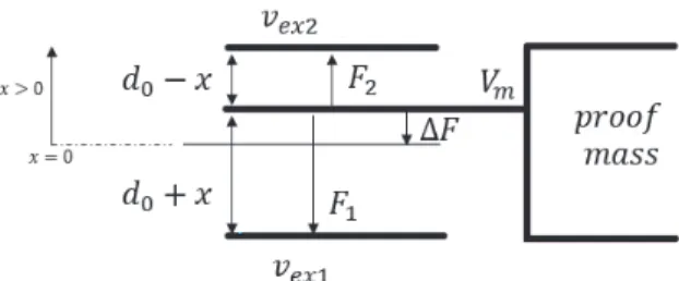
Fig. 1. Parallel plate model of a capacitive sensor.
design that shares its middle plate between the three-axis: x , y and z, and has only one pair of excitation electrodes for each axis, a new interface has been designed in order to enable low power, low surface and high-performance results. The read-out circuit is multiplexed between the three axes to reduce area and a new simultaneous multirate damping technique is applied, to improve the system settling time. To assess the method efficiency, the settling time results are compared to the classical successive damping architecture. Using the multirate signal processing theory, the multirate controller has been modeled and based on the closed loop transfer function, a new stability method is proposed.
This paper is organized as follows: Section II describes the electrostatic damping principle. The novel system architecture and the simultaneous damping chronograms are presented in detail in Section III. Section IV presents the multirate controller modeling and the stability study. Model simulation results are discussed in Section V, followed by the conclusion in Section VI.
II. ELECTROSTATICDAMPINGPRINCIPLE
MEMS accelerometers can be modeled using the second order mass spring damper equation (1). In the presence of an external acceleration aex t, the proof mass m will be deflected
from its equilibrium position with a certain displacement x .
maex t(t) = m ¨x(t) + b ˙x(t) + kx(t)
Q = √
km
b (1)
where k is the spring constant, b the mechanical damping coefficient and Q the quality factor.
When the MEMS cavity pressure starts decreasing, the quality factor Q increases, causing oscillations that can result in measurement perturbations and even in physical part destruction, if the oscillation amplitude is too large. To avoid the above-mentioned inconveniencies, one would develop a control system that reduces the quality factor Q by increasing the damping factor b. By adding a term proportional to the proof mass velocity ˙x(t) in (2), the damping coefficient will be increased with a B value.
maex t(t) = m ¨x(t) + (b + B) ˙x(t) + kx(t) (2)
The electrostatic damping principle consists in generating an electrical damping force (3) that will assist the mechanical damping.
1F(t) = B ˙x(t) (3)
The proposed MEMS structure for one axis comprises three electrodes: one movable electrode, i.e. the proof mass, and two
fixed excitation electrodes (Fig. 1); note also that this movable electrode is shared by the three axes. In the presence of an external acceleration, the proof mass moves, which induces a capacitance variation between these electrodes. In addition, when a voltage is applied on the two fixed electrodes and on the proof mass (vex1, vex2 and Vm respectively), electrostatic
forces are generated; in particular between the proof mass and the excitation electrodes (F1, F2).
The net electrostatic force 1F, detailed in (4), and applied to the proof mass, is an attractive force.
1F = F1− F2= 1 2ε0εrA ! (vex1− Vm)2 (d0+ x)2 −(vex2− Vm) 2 (d0− x)2 " (4) where d0 is the gap at rest between the fixed electrodes and the proof mass and x the proof mass displacement, A the total sense surface, ε0 the vacuum permittivity and εr the relative
vacuum permittivity.
For a parallel plate capacitive sensor, when the voltage difference between the fixed plates and the middle one is 0, no electrostatic force is applied on the proof mass. Let’s suppose for now that on the fixed plates, a differential bias ±VB is
superimposed on the common mode voltage Vm + vctrl as
in (5), then the net electrostatic force applied on the MEMS will depend on both VB and vctrl.
vex1= Vm+ vctrl+ VB
vex2= Vm+ vctrl− VB (5)
where vctrl is the control voltage generated by the control
block to damp the transducer.
Further, if the proof mass displacement is very small compared to d0and the control voltage vctrl is proportional to
the proof mass velocity, then the net electrostatic force applied to the proof mass is also proportional to the velocity as a first-order approximation. In this way, in (2) a new term is artificially added to assist the mechanical damping. The force generated using a control block, during a predefined damping time tdamp within the sampling period Ts is presented in (6).
1F ∼= −tdamp
Ts
2ε0εrA
d02 VBvctrl (6)
Therefore, if the design aim is to have the fastest transducer settling time, a maximum amount of electrostatic force should be applied to the proof mass. From (6) one can notice that several parameters can be adjusted in order to increase the electrostatic force: the excitation electrodes surface, the control voltage and the damping duty cycle. Assuming that the MEMS design parameters are fixed and the maximum control voltage that can be applied is fixed by a certain technology power supply and no charge pump is added, the only parameter which can vary is the damping duty cycle or the electrostatic force application duration.
Nevertheless, note also that the voltage controlled electro-static actuation has several nonlinearities sources such as the voltage to electrostatic force conversion ((6) is an approx-imation that is good as long as the displacement is very
Fig. 2. (a) System block diagram of a closed loop capacitive accelerometer. (b) Successive damping approach chronograms.
small compared with the gap between the electrodes). Conse-quently, increasing the actuation voltage improves settling time performances but also increases nonlinearity; however, for this architecture, the induced non-linearity will be reduced by the gain loop of the system.
III. NOVELSYSTEMDESIGN
The novel discrete time architecture, shown in Fig. 2(a), proposes a new method to improve the damping duty cycle for a transducer that can sense up to three degrees of freedom. The transducer can be modeled using the second order mass spring transfer function Hsens(s), where ω0 is the MEMS natural pulsation. Hsens(s) = 1 k ω02 s2+ω0 Qs+ ω 2 0 (7) In addition, the external acceleration applied to the sensor can be read using the capacitance variation 1C that appears when the proof mass moves. During the measurement phase 81 (Fig. 2(b)), due to the voltage applied on the MEMS electrodes, a charge variation 1Q is injected into a Charge to Voltage converter (C2V) which provides the voltage v to the control block.
The particularity of this architecture is that the C2V is shared between the three-axis, which allows a low power and small area architecture. However, since the C2V, as well as the sensor middle plate, are shared, only one axis measurement can be performed at a time. For example, if during the x-axis measurement phase, a voltage is applied on the y-axis elec-trodes, then parasitical charges will be injected into the C2V and the x-axis acceleration measurement will be corrupted.
Following the C2V, a control block computing the derivative is required in the loop, to provide an estimation of the velocity. As the C2V output reflects the proof mass displacement, the velocity estimation can thus be obtained with the difference between two successive C2V output samples.
vctrl(nTs) = kd[v(nTs) − v ((n − 1) Ts)] (8)
where the derivative gain kd is a design parameter.
Fig. 3. Three-axis closed loop underdamped accelerometer.
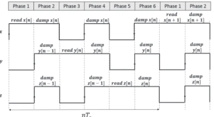
Fig. 4. Proposed chronogams of the simultaneous damping for the x,y and
z axis.
During the damping phase, 82, the previously calculated control voltage is applied on MEMS excitation electrodes. The control voltage is sampled and hold by the derivative block, thanks to a designed capacitive memory, during the entire sampling period Ts.
Furthermore, each axis has its own control block and three derivative signals, corresponding to each of the three axes, are computed during the sampling period Ts. The novelty of
the system presented in this paper consists in simultaneously damping the three axes by applying the corresponding control voltage when the damping phase occurs.
The three-axis underdamped accelerometer MEMS, with the read-out interface and the control blocks, is shown in Fig.3. The MEMS charge variation can be measured using the C2V which has a feedback capacitor Cf bthat will be systematically
reset between each axis measurement. The voltage applied on the MEMS excitation electrodes, will depend on the system operating phase (measurement or damping). Due to the C2V feedback, Vm is applied on the MEMS middle plate during
all phases. Further, the time multiplexed electrodes structure can be translated into a discrete system with simultaneous and multirate damping control. We define Ts the system sampling
period or the time during which all three axes have been measured and damped.
Each of the three derivative blocks will update their output value, and therefore the damping force, only once per period Ts.
A novel sequence, which optimizes the damping efficiency, has been designed and implemented (Fig. 4). Six separate phases can be distinguished in the same sampling period Ts.
For the three-axis: x , y and z, the system has three reading and three damping phases.
During Phase 1, on the x -positive excitation electrode, a 2Vm voltage is applied while the x -negative excitation
elec-trode is connected to the analog ground. In this way, the charge variation, caused by the proof mass movement, is transferred into the C2V. Additionally, after reading x-axis acceleration, the Derivative x control block performs the difference between two successive C2V output samples, and adds a±VB voltage
to the output signal.
When Phase 2 starts, the new x -axis velocity estimation, which has just been calculated during Phase 1, is applied on
x-axis MEMS excitation electrodes, introducing an artificial damping coefficient B in (2), and increasing the mechanical damping coefficient. During the same phase, the y and z velocity estimations that have been previously calculated and stored during the (n− 1)Ts sampling period, can be applied
on y and z excitation electrodes.
When Phase 3 occurs, the voltages applied to the y-axis excitation electrodes are 2Vm and 0V, and a new y-axis C2V
output sample is then available.
A new damping force value is calculated and applied during
Phase 4. Furthermore, the same x damping force, which has been first applied during Phase 2, and still stored, and the
z damping force, which has been calculated in the previous sampling period (n − 1) Ts and hold, are applied on x and z
MEMS electrodes.
Finally, during Phase 5, a new z-axis acceleration value is measured and a new z-axis control signal is available. This new value will then be applied on z-axis excitation electrodes when Phase 6 occurs.
During the same Phase 6, the x -axis damping force which has been first applied during Phase 2 and the y-axis damping force which has been first applied during Phase 4, are also applied on MEMS electrodes.
In this way, when one sampling period is completed, the three axes have been measured once and damped three times; in addition, the electrostatic force applied to the transducer compared to the classical successive reading and damping approach (Fig. 10) is tripled. When the amount of electrostatic force applied is increased so is the artificial damping coefficient and the sensor ability to oscillate are diminished. Consequently, the main parameter one would like to improve is the system settling time.
IV. MULTIRATECONTROLLER ANDSTABILITYSTUDY The overall system has been modeled to find the closed loop transfer function and to conclude on the stability.
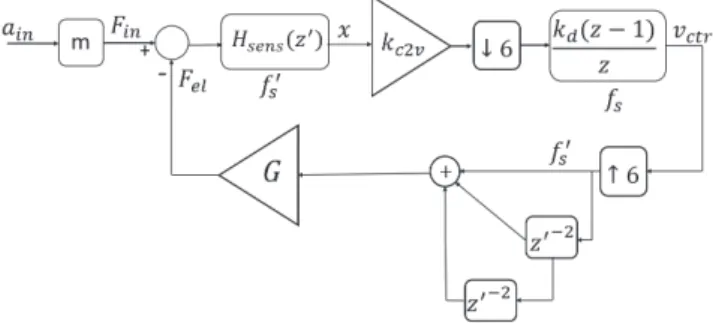
Fig. 5. presents the block diagram for a one-axis high-Q accelerometer with multirate electrostatic damping control. The sampling frequency of each block is shown below them. Note that fs′, which is the MEMS sampling frequency, is the fastest sampling frequency of the system. The MEMS transfer function Hsens#z′$ should be expressed using a high sampling
frequency fs′in order to improve the modeling of the contin-uous time proof mass natural movement.
Firstly, the MEMS accelerometer’s s-domain transfer func-tion (7) is transformed into z-domain using the Bilinear
Fig. 5. Simplified block diagram of the proposed discretized closed loop
accelerometer.
Fig. 6. Discrete model of the closed loop accelerometer architecture using
upsampling / downsampling blocks.
Transform method. HM E M S#z′ $ = 1k γ 2#1+z′$2 z′2%γ2+2 Qγ +4 & +z′#−8+2γ2$ +%γ2−2 Qγ +4 & (9) where γ = ω0Ts′, Ts′= 1/ fs′ and z′= esT ′ s.
Since the C2V bandwidth is much larger than the sensor bandwidth and no filtering is applied to the signal in the first stage of the electronic interface, the C2V operation can be modeled with a constant gain kc2v.
Next, to obtain the derivative transfer function, the
Z-transform is applied to (8). If the controller output is updated once each Ts period, then
vctrl(z) = kd∗ v (z) % 1− z−1 & (10) where z= esTs.
Finally, it has been shown in (6) that the net electrostatic force applied to the proof mass is proportional to vctrl(z).
Therefore, G models the control voltage to electrostatic force conversion gain and is defined as:
G= 2ε0εrA
d02 VB (11)
The electrostatic force is applied three times during the sampling period Ts thus there is a 3G gain to be considered
for the voltage to electrostatic force conversion for one axis. Due to the fact that the system shown in Fig. 5. has more than one sampling rate: Ts and Ts′, one will use the multirate
signal processing theory to model it. Further, since fs′ is the fastest sampling frequency, the blocks having another sampling rate should change it to fs′. The main operations that enable
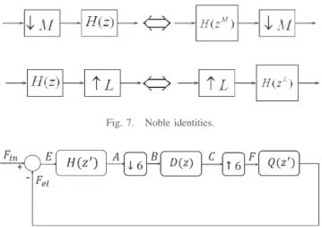
Fig. 7. Noble identities.
Fig. 8. Simplified discrete model of the multirate closed loop accelerometer.
Fig. 9. Equivalent open loop system.
such transformations are the downsampling and upsampling operations [13].
After introducing the upsampling and downsampling, a new block diagram of the model is derived and shown in Fig. 6, where up/downsampling operations are described by the ↑ M/ ↓ M symbol respectively, with M = 6.
Multirate signal processing theory uses the noble identities (Fig.7) to deal with upsampling and downsampling blocks, where H(z) is an arbitrary transfer function.
Therefore, if H#z′$
= kc2v× Hsens(z′), D (z) = kd(z−1)z
and Q#z′$ = G × (1 + z′−2+ z′−4), where z′ = esT′
s and f′
s
the system fastest sampling frequency, the model from Fig. 6. can be depicted in Fig. 8.
To analyze the system presented in Fig. 8, several methods have been proposed in the literature [14], [15]. Due to the downsampling and upsampling processes, this model is time-variant and consequently, an overall transfer function does not exist in the general case. The aim of this study is to find an input-output relationship in the z-domain, based on which, the system stability can be estimated.
Using the Z-Transform and the Noble identities, one can characterize the system presented in Fig. 8, as shown in (12) and (13) at the top of the next page.
But: C % e− j 2πmz′6 & = C % z′6 &
Replacing (13) in (12), eq. (12) can be rewritten as shown in the expressions next to (13), and the electrostatic force output
Fel(z′) expression is found. If we define K#z′$ as: K#z′$ = D#z ′6$ × Q(z′) 1+ D#z′6$ ×1 6 5 ' m=0 H%e−j2π m6 z′ & × Q%e−j2π m6 z′ &
Then the equivalent system is represented in Fig. 9.
The transfer function K#z′$ represents the input-to-output relationship that best describes the discrete multirate controller. Moreover, its stability or instability can be deducted from
K#z′$ stability/instability [9]. It can be noticed that all the transfer functions H#z′$, D (z) = D #z′6$, Q(z′) that appear in the loop in Fig. 8 also appear in K(z)’s characteristic equation: 1+ D % z′6 & ×16 5 ( m=0 H % e−j2π m6 z′ & × Q % e−j2π m6 z′ &
If K#z′$ output is bounded for all bounded inputs, though stable, the overall system is stable. If K#z′$ is unstable, the overall system will be unstable.
This novel approach, validated with behavioral models and numerical simulations, allows studying the stability of a multirate controller for a three-axis high Q MEMS accelerometer.
V. SYSTEMMODELING ANDSIMULATIONSRESULTS
The architecture presented in Fig.3 has been fully modeled and simulated using Matlab – Simulink. The accelerometer MEMS movement was modeled using the equation (1) and the capacitance variation 1C is approximated using the proof mass displacement x .
1C ≈ ε0εrA
d0
x (14)
Sample and hold techniques have been employed to model system sequences and depending on the phase, a different voltage level is applied on the electrodes. The MEMS natural frequency is f0 = 4 k H z and the open loop quality factor Q is 2000 corresponding to a low-pressure cavity of 0.7 torr. Note that although a higher MEMS quality factor implies a lower MEMS Brownian noise (estimated here to be around 1µg/√H z), for this architecture, the electronic noise (≈ 200µg/√H z) is much higher. Consequently, the MEMS cavity pressure advantage is not relevant for the total system noise performances. Here, the MEMS proof mass sensitivity is 1C= 2.5 f F/g (1g = 9.8 m/s2) of capacitance variation. In addition, the charge to voltage converter has been modeled and designed to achieve a sensitivity of V = 13mV /g for a feedback capacitor Cf b = 300 f F and under a 1.6V
power supply. As a result, the system has an acceleration input range of±8g.
However, without any additional damping applied to the MEMS, the system settling time is approximately 400 ms. To assess the damping efficiency, the settling time perfor-mances of the simultaneous damping have been compared with the classical approach, which is the successive damping. In a classical damping approach (i.e. successive damping – see Fig. 10.), the sampling period also comprises six phases; three measuring phases and three damping phases and the three axes are successively measured and damped.
Firstly, both approaches have been modeled and their operation validated. A plot of the closed-loop electrostatic forces for both successive and simultaneous damping is shown in Fig. 11. The electrostatic force applied on the mass should
Fel#z′$ = Q #z′$ × F #z′$ = Q #z′$ × C % z′6& C#z′$ = D #z′$ × B(z′) B#z′$ = 1 6 5 ( m=0 A(e−j2π m6 z′16) B % z′6 & = 16 5 ( m=0 A % e−j2π m6 z′ & A#z′$ = H (z′) × E(z′) E#z′$ = F in#z′$ − Fel(z′) C % z′6 & = D % z′6 & × B % z′6 & = D % z′6 & ×16 5 ( m=0 A % e−j2π m6 z′ & =D % z′6 & ×16 5 ( m=0 H % e−j2π m6 z′ & × E % e−j2π m6 z′ & = D%z′6&×1 6 5 ( m=0 H%e−j2π m6 z′ & ×%Fin % e−j2π m6 z′ & − Fel % e−j2π m6 z′ && = D % z′6 & × )! 1 6 5 ( m=0 H % e−j2π m6 z′ & × Fin % e−j2π m6 z′ & " − ! 1 6 5 ( m=0 H % e−j2π m6 z′ & × Fel % e−j2π m6 z′ & "* (12) Then: 5 ( m=0 Fel % e−j2π m6 z′ & = 5 ( m=0 Q%e−j2π m6 z′ & × C%e−j2π m6 ×6z′6 & (13) C%z′6&= D%z′6&×1 6 )! 5 ( m=0 H%e−j2π m6 z′ & × Fin % e−j2π m6 z′ & " − C%z′6&× ! 5 ( m=0 H%e−j2π m6 z′ & × Q%e−j2π m6 z′ & "* C % z′6 & = D#z′6$ ×16 5 ' m=0 H % e−j2π m6 z′ & × Fin % e−j2π m6 z′ & 1+ D#z′6$ × 1 6 5 ' m=0 H % e−j2π m6 z′ & × Q%e−j2π m6 z′ & Fel#z′$ = Q #z′$ × C % z′6 & = D#z′6$ × Q #z′$ ×16 5 ' m=0 H % e−j2π m6 z′ & × Fin % e−j2π m6 z′ & 1+ D#z′6$ ×1 6 5 ' m=0 H % e−j2π m6 z′ & × Q%e−j2π m6 z′ &
be null during the non-damping phases for the respective axis. Additionally, when the proof mass reaches the steady state and the velocity estimation is 0, the net electrostatic force must reach also a steady state of 0N . The same sampling period Ts = 21µs and derivative gain kd = 400 are used for
both cases. From Fig.11, one can notice the single damping phase for the successive damping approach and the three times application of the same electrostatic force level for the simultaneous damping.
However, to quantify the performances in terms of settling time, additional simulations have been performed. As stated previously, the settling time depends both on Ts and on kdand
consequently, to check the settling performances, the sampling period has been varied from 6µs to 42µs and kd fixed
to 600. It is desired to obtain results compatible within a 1.6V power supply technology, therefore Vm = Vsu pply2 ,
VB= V2m = 0.4V and the control voltage vctrlx is limited to
−0.4V < vctrlx < 0.4V . The settling time simulation results
are presented in Figure 12.
From Fig.12, one can notice that the settling time perfor-mances for the simultaneous damping are better. When the sampling frequency is high, the simultaneous damping is very efficient, and the settling time is, as expected, roughly three times smaller than for the successive damping. Then, when the sampling frequency starts decreasing, the successive damping architecture can be a better choice. The intuitive explanation of the simultaneous damping performances degradation at low sampling frequencies is the loss of correlation between the instantaneous velocity and the electrostatic force value during the second and the third damping phase. When the sampling period is large, it is expected to apply on the excitation electrodes, during the second and the third damping phase,
TABLE I
COMPARISON OFPREVIOUSCLOSEDLOOPACCELEROMETERSWITHTHISWORK
Fig. 10. Successive damping sequence.
Fig. 11. Electrostatic force waveforms for both approaches: successive
(dashed) and simultaneous (solid) damping.
a velocity estimation which is no more related to the real mass movement.
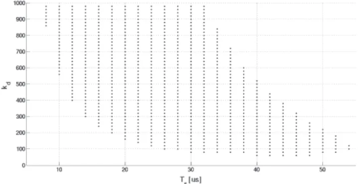
Next, the multirate controller presented in Fig. 6. has been modeled and the K (z′) stability has been completed. Since the system is discrete, if K (z′) has all its poles inside the z-domain unity gain circle, then, the overall system is stable. That is the condition one will impose when choosing the system parameters: derivative gain kd and sampling frequency fs′.
Fig. 13 shows all the pairs (kd, Ts) that drives the system
stable when varying kdbetween 20 and 1000 and Ts between
8 µs and 56 µs (Ts = 6T′s).
Fig. 12. Settling time simulation results for both approaches: successive
damping (dashed) and simultaneous damping (solid).
Fig. 13. Derivative gain and sampling period (kd, Ts) pairs that ensures the
system stability.
When the system is fast, even if the loop gain is large, this will not drive the loop instable. On the other hand, when the sampling frequency starts decreasing, there are a limited number of points for which the system is still stable.
The proposed method can be used, for instance, to choose the design parameters (kd, Ts) of the associated integrated
circuit (IC) implementation of this architecture. The IC has been designed in a 0.18µm CMOS process and its performances are summarized in Table 1, together with
others closed loop accelerometer architectures for comparison purpose.
VI. CONCLUSION
This paper addresses the system design of an analog control architecture, for a three-axis underdamped capacitive MEMS accelerometer having a common proof mass for all-three axis, that allows its cointegration in the same low-pressure cavity with a Coriolis vibratory gyroscope. The analog control of the proof mass is implemented using a new electrostatic damping sequence, which improves the damping efficiency over the state of the art approach (successive damping) in terms of settling time (three times smaller for a sampling time of 24us). The overall system achieves a sensitivity of 13 mV /g for a power consumption of 0.48 mW for the three axes using a 1.6V power supply voltage without requiring any charge pump technique to drive the MEMS electrodes.
In addition, to check the closed loop stability which depends on both the loop gain value and the sampling frequency, a new method to model accurately the system based on multirate signal processing approaches has been analyzed and devel-oped. It also allows to determine the best tradeoff between settling-time and sampling frequency. The proposed analysis hence points clearly out that this method limitation is directly related to the correlation between the measured data and the applied feedback damping force. As expected, the slower the system, the poorer the damping efficiency.
REFERENCES
[1] H. Xu, X. Liu, and L. Yin, “A closed-loop 61 interface for a high-Q
micromechanical capacitive accelerometer with 200 ng/√Hz input noise
density,” IEEE J. Solid-State Circuits, vol. 50, no. 9, pp. 2101–2112, Sep. 2015.
[2] V. P. Petkov and B. E. Boser, “A fourth-order 61 interface for micromachined inertial sensors,” IEEE J. Solid-State Circuits, vol. 40, no. 8, pp. 1602–1609, Aug. 2005.
[3] M. Pastre et al., “A 300 Hz 19b DR capacitive accelerometer based
on a versatile front end in a 5t h-order 16 loop,” in Proc. 35th Eur.
Solid-State Circuits Conf. (ESSCIRC), Sep. 2009, pp. 288–291. [4] M. Kraft, C. P. Lewis, and T. G. Hesketh, “Closed-loop silicon
accelerometers,” IEE Proc. Circuits, Devices Syst., vol. 145, no. 5, pp. 325–331, Oct. 1998.
[5] F. Chen, W. Yuan, H. Chang, I. Zeimpekis, and M. Kraft, “Low noise vacuum MEMS closed-loop accelerometer using sixth-order multi-feedback loops and local resonator sigma delta modulator,” in Proc.
IEEE 27th Int. Conf. Micro Electro Mech. Syst. (MEMS), Jan. 2014, pp. 761–764.
[6] M. Yüceta¸s, M. Pulkkinen, A. Kalanti, and J. Salomaa, “A high-resolution accelerometer with electrostatic damping and improved supply sensitivity,” IEEE J. Solid-State Circuits, vol. 47, no. 7, pp. 1–10, Jul. 2012.
[7] Z. Ye, H. Yang, T. Yin, G. Huang, and F. Liu, “High-performance closed-loop interface circuit for high-Q capacitive microaccelerometers,” IEEE
Sensors J., vol. 13, no. 5, pp. 1425–1433, May 2013.
[8] M. Paavola, M. Kamarainen, J. A. M. Jarvinen, M. Saukoski, M. Laiho, and K. A. I. Halonen, “A micropower interface ASIC for a capacitive 3-axis micro-accelerometer,” IEEE J. Solid-State Circuits, vol. 42, no. 12, pp. 2651–2665, Dec. 2007.
[9] M. A. Lemkin, M. A. Ortiz, N. Wongkomet, B. E. Boser, and J. H. Smith, “A 3-axis surface micromachine 61 accelerometer,” in Proc. IEEE 43rd Int. Solid-State Circuits Conf. (ISSCC), Feb. 1997, pp. 202–203.
[10] M. De Matteis et al., “A 0.13 µm-CMOS 90 µW 51 dB-SNR continuous-time accelerometer front-end with 10b SAR-ADC,” in Proc.
IEEE Sensors, Nov. 2015, pp. 1–4.
[11] M. Zhao et al., “A low-noise closed-loop interface for high-G capacitive micro-accelerometer,” in Proc. IEEE Int. Symp. Circuits Syst. (ISCAS), May 2016, pp. 2415–2418.
[12] Z. Tingting et al., “An s-z domain transformation method for the readout circuit design of closed-loop micromechanical capacitive accelerometer,” in Proc. IEEE Int. Conf. Electron Devices Solid State Circuit (EDSSC), Dec. 2012, pp. 1–3.
[13] M. D. van der Laan, “Signal sampling techniques for data acquisition in process control,” Ph.D. dissertation, Univ. Groningen, Groningen, The Netherlands, 1995. [Online]. Available: https://www.rug.nl/research/ portal/publications/signal-sampling-techniques-for-data-acquisition-in-process-control(84c41c79-8250-4ac9-9fc8-e8a4bb943e75)/export.html [14] G. F. Franklin and J. R. Ragazzini, Sampled-Data Control Systems,
vol. 55, no. 5. New York, NY, USA: McGraw-Hill, May 2007. [15] D. Schwingshackl and G. Kubin, “Polyphase representation of multirate
nonlinear filters and its applications,” IEEE Trans. Signal Process., vol. 55, no. 5, pp. 2145–2157, May 2007.
Lavinia E. Ciotirca received the M.Sc. degree in integrated circuits
design and the Ph.D. degree in micro and nano systems from the National Poly-technique Institute of Toulouse, Toulouse, France, in 2013 and 2017, respectively.
In 2017, she joined NXP Semiconductors, Toulouse, France, as an Analog Mixed IC Design Engineer, where she is currently working on system and circuit design of inertial MEMS sensors for both consumer and automotive applications.
Olivier Bernal (M’03) received the M.Sc. degree in electrical engineering
and the Ph.D. degree from the Institut National Polytechnique de Toulouse, Toulouse, France, in 2003 and 2006, respectively. In 2006, he joined the Institute of Microelec-tronics, Singapore, as a Senior Research Engineer, where he worked on low-voltage and low-power analog circuits for biomedical applications. In 2009, he joined the Laboratory of Optoelectonics and Embedded Systems of the Centre National de la Recherche Scientifique-Laboratoire d’Analyse et d’Architecture des Systemes and the National Polytechnic Institute, University of Toulouse, where he is currently an Assistant Professor. His main research interests are in the design of low-voltage, low-power analog circuit design for optoelectronics and space applications.
Jérôme Enjalbert was born in Toulouse, France, in 1974. He received the
M.Sc. degree in integrated circuit design from the Institut National Polytech-nique de Toulouse, Toulouse, in 1997. He joined Freescale Semiconductor in 1998, where he held several positions in IC design, first as an Analog Design Engineer for power management and audio systems for wireless applications, and since 2009, as a Circuit and System Design Engineer for motion sensors. He is currently with NXP Semiconductors, focusing on the design of advanced MEMS-based accelerometers integrating stiction-recovery and non-physical-stimulus test capabilities.
He holds more than ten patents in the fields of power management, audio, and inertial sensors.
Thierry Cassagnes was born in Toulouse, France, in 1968. He
received the Engineering degree in microelectronics from the Institut National des Sciences Appliquées de Toulouse, France, in 1991.
He joined Freescale Semiconductor, formerly Motorola SPS, in 1994, where he held several posi-tions both in France and USA, as a Senior Analog Design Engineer involved in the design of circuits and systems in the fields of wireless, automotive, and motion sensor applications. He is currently with NXP Semiconductors, where he mainly focuses on the design of MEMS-based gyroscopes and accelerom-eters for both consumer and automotive applications.
Hélène Tap was born in 1973. She received the Ph.D. degree in
microelectronics-microsystems from the Laboratoire d’Analyse et d’Architecture des Systèmes, French Centre National de la Recherche Scientifique, Toulouse, France, in 1999. She is currently a Professor with Laboratoire d’Analyse et d’Architecture des Systemes, Opto-electronics for Embedded Systems Group, Elec-tronics, Electrical Engineering, Computer Science, Hydraulics and Telecommunications Engineering School, National Polytechnic Institute, University of Toulouse, Toulouse. She is mainly working on analog-embedded integrated circuits.
Hugues Beaulaton was born in 1977. He received the B.Eng. degree in
electrical and electronic engi-neering from Nottingham Trent University, U.K., and the M.S. degree in wireless communication systems and signal processing from the University of Bristol, U.K., in 2000.
From 2001 to 2006, he has been a System and Digital Designer specializing in frequency synthesis and homodyne transceivers circuits design at Motorola and Freescale. From 2007 to 2009, he specialized in the high-power amplifiers algorithms for efficiency enhancement. Since 2010, he has been working on inertial sensor (accelerometers and gyroscopes) for automotive and IoT markets at NXP Semiconductors. He holds more than ten patents in the fields of radio-communications and inertial sensors.
Serdar ¸Sahin received the M.Sc. degree in electronics and control engineering
from the Institut National de Sciences Appliquées de Toulouse, Toulouse, France, in 2015. He is currently pursuing the Ph.D. degree in digital commu-nications with the Institut National Polytechnique de Toulouse with CIFRE funding from Thales Communications & Security.
His main research interests are in digital signal processing algorithms, with a focus on PHY-layer digital receivers and cooperative communications.