To cite this version :
Chochol, Marcin and Rissons, Angélique and
Lacan, Jérôme and Vedrenne, Nicolas and Artaud, Géraldine
Evaluation of Error Correcting Code performances of a free space
optical communication system between LEO satellite and Ground
Station
. (2015)
In: Proceedings of SPIE Security + Defense, 21 September 2015 -
24 September 2015 (Toulouse, France).
O
pen
A
rchive
T
OULOUSE
A
rchive
O
uverte (
OATAO
)
OATAO is an open access repository that collects the work of Toulouse researchers and
makes it freely available over the web where possible.
This is an author-deposited version published in :
http://oatao.univ-toulouse.fr/
Eprints ID : 14144
Any correspondance concerning this service should be sent to the repository
administrator:
[email protected]
Evaluation of Error Correcting Code performances of
a free space optical communication system between
LEO satellite and Ground Station
M. Chochol
a, A. Rissons
a, J. Lacan
a, N. Vedrenne
b, G. Artaud
ca
Institut Superieur de l'Aeronautique et de l'Espace (ISAE), 10 Edouard Belin Ave., 31400 Toulouse,
France;
bOnera - The
French Aeropace Lab , 29 Division Leclerc Ave.
,
92322 Chatillon Cédex,
France;
cCentre National d'Etudes Spatiales (CNES), 18 Edouard Belin Ave., 31400 Toulouse,
France
ABSTRACT
Optical communication between LEO satellite and optical ground station creates the opportunity to highly increase the transmitted data rate. The propagation channel has specificities that imply the potential use of error correcting code (ECC) and interleaving at physical and higher layer. A physical layer simulator designed to investigate the performance of the combination of ECC and interleaving in presence of various channel scenarios and receiver architectures is presented here. The simulator emulates signal generation, propagation impairments by the use of dedicated optical attenuation time series provided by state of the art wave optics results and the effect of receiver front-ends with various detection methods. Mutual information (MI) is computed in order to approximate ECC performances. Various receiver architectures and channel scenarios were studied. Among others, direct coupling of the received signal into the photo-detector (PD) or the use of pre-amplified receiver with single mode fiber (SSMF) coupling and optical amplification prior to the detection were considered.
Several receiver architectures were considered: the use of a wide field-of-view detector, SSMF coupling with a single tip/tilt correction or with higher order adaptive optics correction. Two modulations of OOK and DBPSK along with various detection methods were examined. The tuning of ECC parameters was studied through the computation of mutual information. Additionally, the two cases of physical and higher layer interleaving were implemented providing an excellent diversity to the channel seen by the codeword of ECC.
Keywords: LEO satellite, free space, advanced modulation formats, high data rate, optical communication, time series,
mutual information, interleaving, error correcting code adaptive optics.
1. INTRODUCTION
Today, there is a huge motivation to incorporate already working solutions for optical transmission through the ground into the free space. These solutions that can be met in fiber ground communication combine both single and multi-carrier technologies to support lightwave transmission over thousands of kilometers. The transmission in sense of optical ground distribution is not free from errors and individual linear (power losses, dispersion) or nonlinear impairments that constantly lower the signal quality resulting in a high power penalty and a complexity of digital signal processing. The optical transmission related to free space is not free from distortions too [1, 2]. The space environment has own specificity and complexity that cannot be closed in a tube made of silica-fiber material. Apart from that, the optical technologies to support a fiber communication are very promising and easy in further developments [3]. They have no limits in respect to the high–optical speed and its flexibility makes them easy to transfer from fiber solutions to be applicable for space communication. Considering the influence of the atmosphere, in addition to atmospheric transmission that can significantly affect the power received, the transmitted laser beam is affected by atmospheric turbulence [4]. As it propagates in the turbulent atmosphere the laser beam meets index of refraction fluctuations that are mainly due to the mixing of air cells of different temperatures. These fluctuations cause phase perturbations on the beam that result into phase and amplitude fluctuations in the receiver plane after propagation. Amplitude fluctuations account for power in the bucket fluctuations, also known as scintillations. Phase fluctuations exhibit coupling losses when the wave entering the telescope is injected into a single mode fiber. Injection losses can be limited with the use of adaptive optics [5, 6]. The best way to cope with scintillations is to reap the benefit of aperture averaging [7] at the expense of larger receiver diameter (and much more complex AO systems). Another is to consider channel coding theory.
Following the trend on space market, there is a special need to investigate and keep working on new solutions for transmission based on continuous increase of data rate starting from the singles Mb/s up to the hundreds of Gb/s. The
idea itself is not new since it has been transferred from long-haul fiber ground distribution systems which have recently been deployed incorporating single or multilevel solutions. It turned out that the two-fold issue of dispersion impairment and cost became the key point of systems dealing with such an increase in rate. A common trend starting from the increase of bit rate resulted in a shorter bit duration and broader signal spectrum [8]. The narrower bits were becoming much more sensitive to pulse spreading due to dispersion that was successively generating more pulse spreading [3, 8]. Hence, for settling long haul transmission spread over thousands of kilometers in space, the fundamental task becomes to provide a universal solution to investigate and model the propagation in various weather conditions in terms of increased high data bit rate transmission with advanced modulation formats and appropriate detection manner. The accurate and low-cost reception with further detection of highly attenuated optical signals are still the challenges to meet. The treatment is featured by providing an optimal simulation tool. The tool can combine the feasibility of electro-optical system accounted for generation and detection of high-data rate signals along with corrections and visible improvement of performances thanks to the use of channel coding theory.
This paper presents the design and preliminary results of the simulator. Various propagation conditions, modulations and possible detection methods are investigated. The original way to compute mutual information (MI) enables to apply channel coding theory to track and correct errors affecting propagation. The simulation tool guarantees to meet the assumed restrictions and transmission purposes. It will support generation, propagation and detection of 10Gb/s on-off keying (OOK) and differential binary phase shift keying (DBPSK) signals. The original detection methods will be manifested [3, 8]. The demonstration and validation of simulator functionalities will be provided.
The paper is composed of three parts: system architecture, simulator functionality and simulation analysis. At the first section, the system description will concern the two advanced modulation formats (OOK, DBPSK) used to construct transmitter (Tx) and receiver (Rx) architecture incorporating digital signal processing (DSP), optoelectronic devices, passive elements and direct or coherent detection scheme. The second section will provide a description of the simulator to perform tests of proposed system architecture. Finally, the third section will account for overall analysis of system performances in respect to the original way to compute MI [9, 10] and incorporate interleaving as a part of channel coding theory to detect and control more efficiently transmission errors [9, 10].
2. SYSTEM ARCHITECTURE
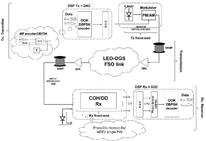
The general architecture is shown on Fig. 1 below. According to the following architecture, the system is divided into the following three main blocks : transmitter (Tx), transmission and receiver (Rx). Each functional part copes with individual transmission matters since the moment of data generation until the time of data reception and error calculations. The intermediate steps called opto-electronic front-ends at both side of the system account for the electro/optics adaptional panel where an electrical to optical conversion is done. To do that, first at Tx, the electrical signal by means of optical modulation is adapted to be transmitted in optics over the space. Secondly at Rx, the collected optical data is being processed choosing one of the appropriate ways to detect data manifested as direct or coherent detection. The chosen optical modulation methods or detection techniques precisely depend on assumed modulation formats. Two modulation formats of DBPSK and OOK, are investigated. In case of DBPSK, right after data generation, a differential encoding is applied. Unlike BPSK, not absolute phase but the change of phase is used to encode binary {0, 1} [1, 3]. Differential encoder works as a precoder. It generates precoded data equal to the sum of binary data and precoded symbols delayed about 1 bit in respect to the output [3]. Next, precoded symbols are fed into the digital-to-analog converter (DAC) where by applying upsampling and low-pass equivalent filtering, the shape of electrical NRZ pulse is formed. The obtained electrical DBPSK-NRZ signal is then employed to drive a phase modulator (PM) and modulate the phase of optical carrier [3]. The continuous wave (CW) laser along with optical modulator exhibit the opto-electronic end [3]. The continuous wave (CW) laser along with optical modulator exhibit the opto-opto-electronic front-end [3]. In case of OOK modulation format, no precoding is applied. OOK denotes the simplest form of ASK modulation with one bit per symbol, where the two states of amplitude ensure correct encoding of binary {0, 1} [3]. Continuing, the OOK symbols are fed into the same DAC as in DBPSK case. DAC provides a real time value output of electrical OOK-NRZ applied to modulate amplitude of optical carrier using optical intensity/amplitude modulator (IM/AM). Subsequently, next to the Tx, both optical signals of DBPSK/OOK-NRZ travers across the FSO link.
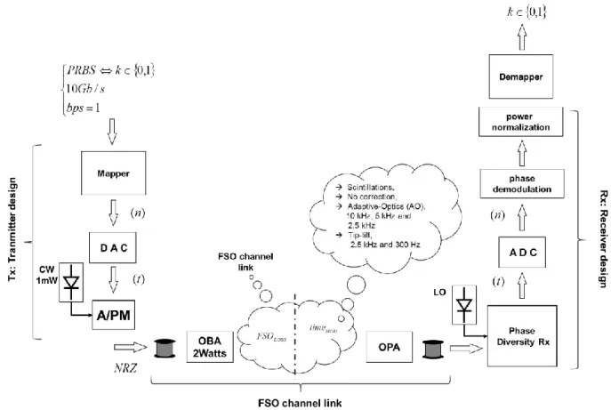
The optical link featuring the transmission part is given on Fig. 2 below. The transmission link contains the three important parts, optical booster amplifier (OBA), FSO link that stands for a LEO-OGS communication and optical pre-amplifier (OPA) right before reception. Both OBA and OPA refer to the well-known on market an erbium doped fiber amplifier (EDFA). First, an incoming optical signal is fed into a short SSMF and boosted at OBA to get an acceptable level for transmitting over long distance. The optical wave is then propagated through the atmosphere using state of the art wave optics results [11].
Figure 1. System architecture to feature a LEO-OGS transmission.
Both static losses (geometric losses, atmospheric attenuation) featured by long term effects and dynamical fluctuations acted as time varying effects due to scintillations and coupling losses are taken into account.
After traversing the space, being strongly attenuated, the signal gets pre-amplified at OPA. Consequently, the receipted signal is then fed to a SSMF terminated with the appropriate detection scheme depending on chosen modulation format. Next, the received optical DBPSK/OOK-NRZ signal is on the input of detection scenario. In case of DBPSK format, there are two possible detection schemes limited to coherent and direct detection based on the structure of Mach-Zehnder (MZ) interferometer delay [3, 8, 10, 13]. In case of OOK format, there is only one imposed detection scheme based on single photo-diode [3, 8]. Formally, there is a lot of ideas to support coherent detection unlike direct detection. Using a coherent approach, the signal can be fully reconstructed in phase, amplitude and polarization. Although, this method is not really cost-effective, it guarantees a full synchronization between the Tx and Rx. Unlike a coherent detection, a direct detection is only based on a simple off-the-shelf scenario to only struggle with a signal intensity. It is less complex and provides a sufficient detection coverage in some cases.
Coming closer to coherent detection, the most popular is an approach based on homodyne structure with the phase diversity receiver (PhaseDiv Homod-Rx). The phase diversity receiver combines 90º optical hybrid with the two pairs of photodetectors featured by positive-intrinsic-negative (PIN) diodes acted as balanced detectors [3, 8]. Next, the PIN outputs are given to initiate a digital processing and finally reproduce data. The chain of blocks participating in DSP starts from the analog to digital conversion (ADC) where both, downsampling operation with reconstruction filtering are operated. The phase demodulation is made only in case of optical phase modulation at Tx side. Next, a power normalization along with a DBPSK demapping lead to the final data recovery. In turn, a balanced direct detection based on the structure of MZ interferometer delay (MZID) is considered as an alternative detection for DBPSK signals. The structure partially refers to the well-known coherent detection. Unlike a coherent detection, a direct balanced detection has no synchronization with Tx and it contains less complexity with a reduced number of PINs [3, 8].
A final demapping executed in optical domain formally differs and simplifies a fully electrical DSP made in coherent manner. Subsequently, a single PIN diode is proposed for pure optically modulated OOK signals. The signals crossing by single PIN get squared due to the effect of photo-detection fall.
Figure 2. Channel architecture to feature a LEO-OGS transmission.
The single photo-detector offers better flexibility and profitability due to the use of simple off-the-shelf components. Nevertheless, its performances are limited and show lower spectral efficiency unlike more complex balanced or coherent solutions.
3. SIMULATOR FUNCTIONALITY
The main purpose of the paper is to provide the functional simulation model of one-carrier system explained in principle in the previous section. The simulator is mainly devoted to physical layer. The goal to deliver a working model of simulator to exhibit an optical transmission between LEO satellite and OGS in terms of various weather conditions and transmission features (modulation formats, detection schemes etc.) has been achieved. The simulator has been tested by means of simulations using Matlab software. The system performances from electro-optical fields and error analysis based on channel coding theory were checked out. The simulator functionality is split into the three parts. Each part stands for one stage of simulations manifesting the ideas spread over propagation aspects or errors evaluation. The realistic model of simulator is seen on Fig. 3 below. In first part, the parameter settings are established. There are several parameters to be used and varied while simulating. Generally, the transmission of 10Gb/s OOK/DBPSK-NRZ signals with 1 bit per symbol (bps) was investigated. Using pseudo random bit sequence (PRBS) generator, 5*105 data bits of
kϵ{0,1} were generated and applied to do a Tx design. Next, at DAC the analog counterpart of discrete signal is managed. Hence, a full real-valued electrical NRZ pulses are generated and used to drive a proper AM or PM modulator, depending on the chosen modulation format. In case of OOK-NRZ, AM modulator is applied unlike DBPSK-NRZ where PM modulator needs to be placed. The laser modelling is done. The typical parameters used while emulating a continuous wave laser are linewidth, output power and sample rate. The laser has no phase noise and generates 1mW of optical power. Analyzing electro-optical modulators, PM modulator is followed by an input optical field and electrical signal of driving voltage and a voltage of π phase shift exerted on optical carrier. In case of AM modulator with no chirp effect, a proper biasing, driving voltage and a voltage of π need to be setup. Then, optical output array in NRZ optical format, is ready to be sent over the FSO channel link. It contains the three elements as, OBA, FSO channel link and OPA. First, a signal is boosted up to 2Watts using an optical EDFA at Tx named as OBA.
Prior to the OBA, a signal is launched to the short length of SSMF fiber. Afterwards, the OBA is implemented. An optical noise is computed and added to the amplified signal. The optical amplified spontaneous emission (ASE) noise is implemented by adding white Gaussian noise to obtain a certain optical signal to noise ratio (OSNR) value at 0.1nm of OSNR BW. Having 2Watts of optical power, the system launches it into the FSO link that is characterized combining the two effects of FSO static losses and attenuation time series. Prior to the time series, FSO losses of -61dB corresponding to 1592km link between LEO and OGS are set. These losses correspond to the cumulated effects of geometric losses with a 8 cm emitter and 40cm receiver (- 37,7dB), optical losses at emitter and receiver side (-14,8dB), and atmospheric transmission losses (-8,5dB). The total duration of the time series is 2s. Atmospheric parameters for the time series are given here. Fried parameter of the simulations is 1.5cm @ 550nm at zenith so that to be representative of strong daytime turbulence conditions. The Cn² profile is a Hufnagel-Valley turbulence profile with a 27m.s-1 wind
parameter and Cn² = 1.7 10-13 m-2/3 at ground level. Wave optics simulations are performed for a 20° elevation. Several
Figure 3. Step-by-step model of simulator in MATLAB software.
stands for scintillation effects only. This corresponds to the particular case of a wide enough detector to enclose the focal spot every time. To investigate a wide variety of coupling losses, six cases were provided: three cases of high order AO correction (190 Zernike modes corrected) with decreasing sampling frequency for the control loop (10kHz, 5kHz and 2.5kHz), two cases with a low order correction of tip/tilt modes only (2.5kHz and 300Hz) and one case without any correction.
When correction is considered, wavefront sensing is performed using a diffractive model of a Shack-Hartmann wavefront sensor with 18x18 square subapertures. Scintillations and noise influence on wavefront sensing are taken into account. After simulating image formation at the focal plane of each subaperture, detector noise and photon noise are added. Standard deviation of detector noise is set 200 photoelectrons per pixel and per frame. The control loop is performed using a state of the art proportional integrator feedback loop with 2 frames delay and servo-loop gain set to 0.5. After traversing over the space, a pure highly attenuated optical signal is going to be receipted. OPA gives an amplification level satisfied by PDs applied. OPA is emulated in a similar way related to OBA before transmission. Then, an optical signal is fed into the short SSMF and in case of coherent system, it interferes with LO (synchronized in phase and frequency with a CW laser) at the input of phase diversity receiver. The design of phase diversity Rx depends on the chosen modulation scheme. PDs used during tests are PIN diodes. In general, PINs are cheaper, less complex and have a small absorbing area just to be plugged into the fiber.
Subsequently, the representation of electrical baseband analog signal is converted into the digital domain applying ADC. All of DSP operations are a mirror reflection to all of these applied to Tx. Therefore, all three of phase demodulation, power normalization or data demodulation, are carried out in reference to the considered modulation scheme.
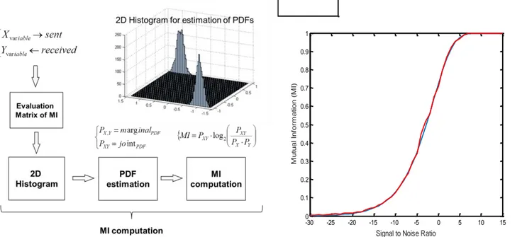
Apart from the transmission issues, there is an original part focused on further ECC performance analysis using a channel coding theory. The approach consists in evaluating the ECC performance by estimating the amount of mutual information (MI) received by the codewords of a given ECC. For varying channels, this method is much more efficient than e.g. average BER estimation at the input of ECC [9]. The use of MI, which basically corresponds to the channel capacity, for the estimation of ECC is not really new [9, 12], but the originality here is more in the method used to compute MI. Indeed, the lack of accurate models for the channel and for the performances of the various mechanisms of amplification, detection or demodulation makes the computation of MI extremely difficult. To compute a MI, several
steps were executed. First, the MI evaluation matrix was drawn. The matrix consists of the two elements that commonly correspond to each other, e.g. bits or symbols sent in respect to signals or symbols received. The matrix elements of sent and received symbols are random variables. For the received variables, the probability density function (PDF) needs to be calculated. In order to estimate this density function, a transmission of a large number of symbols is done. Then, the 2D histogram can be constructed and computed. These steps help to determine final marginal and joint PDF functions corresponded to the matrix variables. All the following steps to reach a final MI and start doing an investigation on ECC are illustrated on Fig. 4-left. Additionally an example of 2D histogram for PDFs estimation is shown. The accuracy of MI estimation with a comparison between theory and proposed estimation is provided on Fig. 4-right.
-30 -25 -20 -15 -10 -5 0 5 10 15 0 0.1 0.2 0.3 0.4 0.5 0.6 0.7 0.8 0.9 1
Signal to Noise Ratio
M u tu a l In fo rm a ti o n (M I)
Figure 4. Step-by-step model to estimate MI (left) with MI proof (right).
Subsequently, based on calculated MIs, ECC performances with included interleaving features are investigated incorporating a channel coding theory.
4. SYSTEM PERFORMANCES
The system proposed to support a transmission of 10 Gb/s with OOK/DBPSK between LEO-OGS is successfully managed to work. Several tests are executed. The tests refer to the system performances of MI and packet error rate (PER) in respect to various turbulence conditions stored in time series provided. The final performances are obtained for the two types of detection of direct (DD) and coherent (COH) taking into account an OPA amplifier gain and reported internal modulations. PINs have been set to catch all highly attenuated optical power. Total time duration of each time series corresponds to 2s. The number of 20000 time sample points refers to the time series duration, however time duration of a single time interval is equal to 0.1ms. These parameters are chosen to make maximally sufficient long term simulations. Based on ECC, the sender properly encodes data in a redundant way where beside data bits, redundant bits for error control are located. Next, for a given rate of ECC, the curves of packet error rate (PER) directly calculated from MIs are implemented. The standardized codes of DVB-S2 of several examples of coding rates e.g. ½, 3/4 or 5/6 are tested. ECC with the two classes of interleaving is pictured. A physical layer interleaving is demonstrated as a potential way to provide diversity to the channel seen by individual codeword of ECC. Thereby, a higher layer interleaving acts as a tool struggling with errors while transmitting across MAC or transport layer. Following the study of MI, prior to the ECC analysis, several tests were made to support the interest of MI.
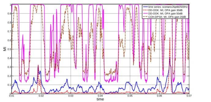
Several types of results obtained by the simulator can be presented. We chose to present in Fig. 5 the behavior in terms of MI of two pairs of detection-modulation schemes (DD-OOK and COH-DPSK) with various OPA gains.
0.010 0.02 0.03 0.04 0.05 0.06 0.07 0.1 0.2 0.3 0.4 0.5 0.6 0.7 0.8 0.9 1 time MI
time series: scenario2tiptilt2500Hz DD-OOK: MI, OPA gain 30dB DD-OOK: MI, OPA gain 50dB COH-DPSK: MI, OPA gain 20dB
Figure 5. MI for OOK-DD and tip-tilt of 2500 Hz for various OPA gains.
Fig. 5 is tested in a zoomed period of time up to 0.07s for a better visualization. The time axis reflects to the assumed length of time series ranging between 0-20000 time intervals. The values of OPA gain have a significant impact on the final MI fluctuations. The channel here is featured by the chosen time series of tip-tilt with a correction frequency of 2.5kHz. MI follows the channel fluctuations in both cases. In case of OOK-DD, the lower (insufficient) the level of gain is, the poorer final performances are. It is noticed that at 30dB of OPA gain, MI oscillates lower or closely to the same level of channel fluctuations that obviously limits the efficient reception. Here, additional dBs added easily improve MI performance and error estimation. Similar conclusions can be admitted for DPSK-COH, where much lower gain of 20dB is added to satisfy similar level of MI oscillations denoted with 50dB for OOK-DD.
0 0.1 0.2 0.3 0.4 0.5 0.6 0.7 0.8 0.9 1 0 0.05 0.1 0.15 0.2 0.25 0.3 0.35 0.4
PL time interleaver [s] (-> PLIL)
P
L
P
E
R
DPSKcoh, no-correction, OPA 40dB, PLCR=1/2 PLCR=3/5
PLCR=2/3 PLCR=3/4 PLCR=4/5 PLCR=5/6
Figure 6. PLPER of DPSK-COH, for various PL coding rates and for PL time interleaver.
Subsequently, the effect of physical layer (PL) and higher layer (HL) interleaving for the chosen case of DPSK-COH is discussed. To do that, physical layer packet error rate (PLPER) and higher layer packet error rate (HLPER) are being computed in a function of PL/HL time interleaver translated to physical laver interleaver length (PLIL) or higher layer
interleaver length (HLIL) respectively. The results affiliated by time series with no-corrections and fixed OPA conditions are featured on Fig. 6 and 7. In terms of no-correction’s time series, the incoming flux entering the telescope is coupled into a SSMF that leads to PIN diode and no specific correction of the wave front is provided.
In case of analysed Fig. 6, a PL interleaver is being tested for various physical layer coding rates (PLCRs) ranging between ½-5/6. The smooth decrease of PLPERs with an increase of interleaver length for each coding rate is noted. The highest PLPER is achieved for the highest PL coding rate of 5/6. Putting attention on Fig. 7, a PL interleaver length is fixed to 20 and HLPERs are exhibited in the function of time. The global coding rate (globCR) is constant and equal to ½. By increasing a PLCR and decreasing higher layer coding rate (HLCR), a drop of HLPER is noticed. The highest HLPER is caught at the highest coding rate of 5/6.
0 0.2 0.4 0.6 0.8 1 1.2 0 0.05 0.1 0.15 0.2
HL time interleaver [s] (-> HLIL)
H
L
P
E
R
DPSKcoh, no-correction, OPA 40dB, globCR=1/2 PLCR=3/5, HLCR=5/6, PLIL=20
PLCR=2/3, HLCR=3/4, PLIL=20 PLCR=3/4, HLCR=2/3, PLIL=20 PLCR=4/5, HLCR=5/8, PLIL=20 PLCR=5/6, HLCR=3/5, PLIL=20
Figure 7. HLPER of DPSK-COH, for various PL coding rates and for HL time interleaver.
5. CONCLUSIONS
The aim of the article was to deliver the functional simulator of physical layer to feature the optical transmission in range of LEO satellite and optical ground station. The coarse evaluation of ECC performances including the two types of interleaving was provided. There are various parameters from both, physical and coding part that have a significant impact on final performances in range of MI and ECC analysis. Among the various parameters, the most crucial are time series, pre-amplifier gain, modulation and detection scenario along with coding rate and interleaver length. MI became an interesting statistic to evaluate an optical transmission over a free space. Despite a number of advantages unlike BER, MI provides a much more efficient estimation at the input of ECC. Physical and higher layer interleaving act a one by one in respect to assumed layer. PERs obtained in the two scenarios of interleaving (Fig. 6-7) give several drops and growths depending on interleaving length and coding rate.
REFERENCES
[1] Ghassemlooy Z., “Optical Wireless Communications,” CRC Press, 2013
[2] Muhammad S. S., et. al, “Channel Modeling for Terrestrial Free Space Optical Links,” in Proc. of International Conference on Transparent Networks (ICTON), pp. 407-410, 2005
[3] Binh L.N. “Optical Fiber Communications Systems,” CRC Press, 2010
[4] Fante R., “Electromagnetic beam propagation in turbulent media,” Proc. of the IEEE, 63(12):1669–1692, 1975 [5] Shaklan S., et. al, “Coupling starlight into single-mode fiber optics,” Appl. Opt. 27, 2334-2338, 1988
[6] Kaufmann J.E., “Performance limits of high-rate space-to-ground optical communications through the turbulent atmospheric channel,” Proc. SPIE 2381, Free-Space Laser Communication Technologies VII, 171, 1995
[7] Fried D.L., “Aperture Averaging of Scintillation,” J. Opt. Soc. Am. 57, 169-172, 1967
[8] “Multiplexing, Modulation and Detection. What is the best mix?,” Submarine White-Paper, XTERA Communications Inc., January 2010
[9] Chauvet W., et. al, “Physical layer DVB-SH performance prediction based on mutual information,” International Journal of Satellite Communications and Networking, Volume 30, Issue 5, pages 193–211, September/October 2012 [10] Fidler F., et. al, “Optical Communications for High-Altitude Platforms,” IEEE Journal of Selected topics in
Quantum Electronics, vol. 16, no. 5, Oct. 2010
[11] Védrenne N. et al., “Turbulence effects on bi-directional ground-to-satellite laser communication systems,” Conference on Space Optical Systems and Applications (ICSOS) 2012, France, October 9-12, 2012
[12] Moision B., et. al, “Fading losses on the LCRD free-space optical link due to channel turbulence,” in Proc. of SPIE 8610, Free-Space Laser Communication and Atmospheric Propagation XXV, 86100Z, vol. 8610, March 2013 [13] Urick V., et. al, “Long-Haul Analog Photonics,” Journal of Lightwave Technology, vol. 29, no. 8, pp. 1182–1205,