HAL Id: pastel-00662744
https://pastel.archives-ouvertes.fr/pastel-00662744
Submitted on 25 Jan 2012
HAL is a multi-disciplinary open access
archive for the deposit and dissemination of sci-entific research documents, whether they are pub-lished or not. The documents may come from teaching and research institutions in France or abroad, or from public or private research centers.
L’archive ouverte pluridisciplinaire HAL, est destinée au dépôt et à la diffusion de documents scientifiques de niveau recherche, publiés ou non, émanant des établissements d’enseignement et de recherche français ou étrangers, des laboratoires publics ou privés.
UML-Based Design Space Exploration, Fast Simulation
and Static Analysis
Daniel Knorreck
To cite this version:
Daniel Knorreck. UML-Based Design Space Exploration, Fast Simulation and Static Analysis. Elec-tronics. Télécom ParisTech, 2011. English. �pastel-00662744�
N°: 2009 ENAM XXXX
2011-TELP-00XX
EDITE de Paris
présentée et soutenue publiquement par
Daniel Knorreck
26/10/2011
UML-Based Design Space Exploration,
Fast Simulation and Static Analysis
Doctorat ParisTech
T H È S E
pour obtenir le grade de docteur délivré par
Télécom ParisTech
Spécialité “ Electronique ”
Directeur de thèse : Ludovic Apvrille Co-encadrement de la thèse : Renaud Pacalet
T
H
È
S
E
JuryMme. Laurence Pierre, Université Joseph Fourier, Grenoble, France Présidente
M. Lothar Thiele, Swiss Federal Institute of Technology, Zürich, Swisse Rapporteurs
M. Frédéric Mallet, Université Nice Sophia Antipolis, Sophia Antipolis, France
Mme. Cécile Belleudy, Université Nice-Sophia Antipolis, Sophia Antipolis, France Examinateurs
M. Jean-Luc Danger, Télécom ParisTech, Paris, France
M. Ludovic Apvrille, Télécom ParisTech, Sophia Antipolis, France Directeurs
UML-B
D S E,
F S S A
Daniel Knorreck
COMELEC, Institut Telecom, Télécom ParisTech
A thesis submitted for the degree of
Doctor of Philosophy from Télécom ParisTech
Reviewers:
Prof. Dr. Lothar Thiele, Swiss Federal Institute of Technology Zürich Prof. Dr. Frédéric Mallet, Université Nice Sophia Antipolis, France
Supervisors:
Prof. Dr. Ludovic Apvrille, Télécom ParisTech Prof. Renaud Pacalet, Télécom ParisTech, France
«Never write anything that does not give you great pleasure. Emotion is easily transferred from the writer to the reader.»
Joseph Joubert
Acknowledgements
All along this work, I had the pleasure to meet inspiring people that encour-aged me, gave me advice, shared their opinion with me, guided me or were simply there when I needed someone to talk to. Without their valuable assis-tance, I wouldn’t have succeeded this thesis. As all these people helped me in their own special way, it would be unfair to put their names in an order. That is why I chose the following way to express my gratitude:
X X R R J I P E J K C L H Z F X L I G A D M C L I K V E T H M A A E B E L L E U D Y N R W J U D S A R A B E A C M D A H F D H E U R E C O M D H R U O G S E B A S T I E N X W I D C A F P M A L L E T O M J K E I B X B Q R R L P I E R R E L N R Z F V T O C H A F I C T R E I D E H T D A N G E R O D E Q E X R A L E X A N D R E Q N T L T I Q L U D O V I C H X A C Z D E B B E R N D P A U L U B S A L C A R I N A C C T E D W R P I N T H I E L E B V M P H
Abstract
Abstract: Design Space Exploration at system level is carried out early in the design flow of embedded systems and Systems-on-Chip. The objective is to identify a suitable hardware/software partitioning that complies to a given set of constraints regarding functionality, performance, silicon area, power consumption, etc. In early design stages, accurate system models, such as RTL models, may not yet be available. Moreover, the complexity of these models comes with the downside of being demanding and slow in verification. It is commonly agreed that the only remedy to that problem is abstraction, which triggered the advent of virtual platforms based on tech-niques like Transaction Level Modeling. Non-functional, approximately timed models go even further by abstracting data to its mere presence or absence and introducing symbolic instructions.
The DIPLODOCUS methodology and its related UML profile realize the aforementioned abstractions. It relies on the y-Chart approach, that treats functionality (called application) and its implementation (called architecture) in an orthogonal way. DIPLODOCUS’ formal semantics paves the way for both simulation and formal verification, which has been shown prior to this work. This thesis proposes enhancements to the methodology that make it amenable to verification of functional and non-functional properties.
At first, we focus on the way functional properties are expressed. As veri-fication of high level models is usually conducted with temporal logic, we suggest a more intuitive way, matching the abstraction level of the model to be verified. The graphical but formal language TEPE is the first contribu-tion of this work. To achieve a high level of confidence in verificacontribu-tion in a reasonable amount of time, the model needs to be executed in an efficient way. The second contribution consists of an execution semantics for DIPLO-DOCUS and a simulation strategy that leverages abstractions. The benefit is that a coarse granularity of the application model directly translates into an increase in simulation speed. As a third contribution, we present a trade-off between the limited coverage of simulation and the exhaustiveness of formal techniques. Especially for large models, the latter may be hampered by the state explosion problem. As a result of data abstraction, DIPLODOCUS ap-plication models embrace non-deterministic operators. Coverage-enhanced simulation aims at exploiting a subset or all valuations of the corresponding random variables. Therefore, the DIPLODOCUS model is statically analyzed
and information characterizing the significant state space of the application is propagated to the simulator.
Finally, we provide evidence for the applicability of contributions by means of a case study in the signal processing domain. It will be shown that com-mon system properties easily translate into TEPE. Moreover fast simulation and coverage-enhanced simulation provide valuable insights that may assist the designer in configuring a Software Defined Radio platform.
Keywords: Embedded Systems, System-on-Chip, Modeling, UML, SysML, Abstraction, Simulation, Verification, Graphical Property Language, System Level, Coverage
Résumé: L’exploration de l’espace de conception au niveau système est
effec-tuée tôt dans le flot de conception des systèmes embarqués et des systèmes sur puce. L’objectif est d’identifier un partitionnement matériel / logiciel approprié qui réponde à un ensemble de contraintes concernant la fonction-nalité, la performance, la surface de silicium, la consommation d’énergie, etc. Lors des étapes de conception précoces, des modèles de système précis, tels que des modèles RTL, peuvent être encore indisponibles. Par ailleurs, la com-plexité de ces modèles présente l’inconvénient d’être exigeant et lent dans la vérification. Il est communément admis que le seul remède à ce problème est l’abstraction, ce qui a engendré l’apparition de plates-formes virtuelles basées sur des techniques telles que la modélisation au niveau transaction-nel. Étant non fonctionnels, les modèles approximately timed vont encore plus loin en faisant l’abstraction de données simplement selon leur présence ou absence et en introduisant des instructions symboliques.
La méthodologie DIPLODOCUS et son profil UML correspondant réalisent les abstractions susmentionnées. La méthodologie s’appuie sur l’approche en Y, qui traite des fonctionnalités (appelées application) et leur réalisation (appelée architecture) de manière orthogonale. La sémantique formelle de DIPLODOCUS ouvre conjointement la voie à la simulation et à la vérifica-tion formelle, ce qui a été démontré préalablement a ce travail. Cette thèse propose des améliorations à la méthodologie qui permettent la vérification des propriétés fonctionnelles et non fonctionnelles.
Au début, nous nous concentrons sur la façon dont les propriétés fonction-nelles sont exprimées. Puisque la vérification des modèles de haut niveau est habituellement réalisée avec la logique temporelle, nous suggérons une façon plus intuitive qui correspond au niveau d’abstraction du modèle qui doit être vérifié. Le langage graphique, mais formel nommé TEPE est la pre-mière contribution de ce travail. Pour atteindre un niveau élevé de confiance en vérification dans un délai raisonnable, le modèle doit être exécuté
effi-cacement. La deuxième contribution vise donc une sémantique d’exécution pour les modèles DIPLODOCUS et une stratégie de simulation qui s’appuie sur l’abstraction. L’avantage est qu’une granularité grossière du modèle d’application se traduit directement par une augmentation de la vitesse de simulation. Comme troisième contribution, nous présentons un compromis entre la couverture limitée de la simulation et l’exhaustivité des techniques formelles. Lorsqu’il s’agit de modèles complexes, l’exhaustivité peut être en-travée par le problème d’explosion combinatoire. En raison de l’abstraction de données, les modèles d’application DIPLODOCUS comportent des opéra-teurs non-déterministes. La simulation à couverture élargie vise à exploiter un sous-ensemble, ou bien l’intégralité, des valeurs des variables aléatoires. Par conséquent, une analyse statique des modèles DIPLODOCUS est effec-tuée et les informations caractérisant la partie significative de l’espace d’état de l’application sont propagées au simulateur.
Enfin, nous fournissons des preuves de l’applicabilité des contributions par le biais d’une étude de cas dans le domaine du traitement du signal. Il sera démontré que les propriétés courantes se traduisent aisément en TEPE. Par ailleurs, la simulation rapide et sa couverture élargie fournissent des indica-tions pertinentes qui sont susceptibles d’aider le développeur à configurer une plate-forme radio logicielle.
Mots clés: Systèmes embarqués, Systèmes sur Puce, Modelisation, UML, SysML, Abstraction, Simulation, Vérification, Langage de propriétés graphique, Niveau Système, Couverture
Contents
Contents vi
List of Figures xi
1 Introduction 1
1.1 Problem Statement . . . 2
1.2 Objectives and Contributions . . . 4
1.3 Outline . . . 5
2 The DIPLODOCUS environment for Design Space Exploration 7 2.1 Introduction . . . 7
2.2 Design Space Exploration . . . 7
2.3 Methodology . . . 9 2.3.1 Application model . . . 10 2.3.2 Architecture model . . . 11 2.3.3 Mapping . . . 13 2.3.4 Nomenclature . . . 13 2.4 A word on MARTE . . . 14 2.5 Model calibration . . . 15
2.6 Putting Contributions into context . . . 17
2.7 Conclusions . . . 18
3 Approaches for System Level DSE and Verification 20 3.1 Introduction . . . 20
3.2 Models of Computation . . . 20
3.2.1 Finite state machines and Statecharts . . . 24
3.2.2 Data Flow Networks . . . 25
3.2.3 Discrete event . . . 26
3.3 Classification . . . 26
3.4 Verification techniques . . . 30
3.4.1 Formal and static methods . . . 30
3.4.1.1 Event Stream Composition . . . 31
3.4.1.2 Operational Analysis . . . 31
3.4.1.3 Symbolic Computation . . . 31
3.4.1.4 Static program analysis . . . 32
3.4.1.5 Symbolic Simulation . . . 32
3.4.1.6 Model Checking . . . 33
3.4.2 MoC-centric methods . . . 34
3.4.3 Simulation centric methods . . . 35
CONTENTS
3.4.3.2 Explicit Control Flow based methods . . . 37
3.4.3.3 Trace based approaches . . . 40
3.4.4 Hybrid Static/Simulation methods . . . 41
3.4.5 Communication centric methods . . . 42
3.4.6 Improving simulation speed . . . 42
3.4.6.1 Timing abstractions . . . 43
3.4.6.2 Simulation techniques . . . 43
3.4.6.3 Towards native execution . . . 44
3.5 Property specification . . . 45
3.5.1 Non-UML approaches . . . 45
3.5.2 UML approaches . . . 46
3.5.3 Tooling . . . 47
3.5.4 Conclusions . . . 47
3.6 Modeling and visualization . . . 48
3.7 Conclusions . . . 48
4 TEPE - A formal, graphical verification language 51 4.1 Introduction . . . 51
4.2 Formal toolbox . . . 52
4.2.1 Metric Temporal Logic (MTL) . . . 52
4.2.2 Fluent Linear Temporal Logic (FLTL) . . . 53
4.3 TEPE: TEmporal Property Expression language . . . 55
4.3.1 Requirements modeling with SysML Requirement Diagrams . . . 55
4.3.2 Parametric Diagrams . . . 55
4.3.2.1 Intuition . . . 55
4.3.2.2 Construction . . . 57
4.3.2.3 Example . . . 58
4.3.3 Links . . . 59
4.3.4 Generic TEPE Constraints . . . 60
4.3.5 Attribute constraints . . . 61
4.3.5.1 Attribute Declaration . . . 61
4.3.5.2 Setting . . . 61
4.3.5.3 Equation . . . 62
4.3.6 TEPE Signal constraints . . . 62
4.3.6.1 Signal declaration . . . 62 4.3.6.2 Signal Alias . . . 63 4.3.6.3 Sequence Constraint . . . 63 4.3.6.4 Logical Constraint . . . 64 4.3.6.5 Temporal Constraint . . . 65 4.3.7 Property Constraints . . . 66 4.3.7.1 Property Logic . . . 66 4.3.7.2 Property Label . . . 67
4.4 TEPE and AVATAR . . . 67
4.4.1 AVATAR Methodology . . . 68
4.4.2 AVATAR Block and State Machine Diagrams . . . 68
4.4.3 Harmonising AVATAR and TEPE . . . 69
4.4.4 System design example . . . 69
4.5 TEPE and DIPLODOCUS . . . 69
4.5.1 Harmonising DIPLODOCUS and TEPE . . . 70
4.5.2 Example . . . 71
CONTENTS
4.5.2.2 Property modeling . . . 72
4.5.3 Implementation Issues . . . 74
4.5.3.1 TEPE Verifier Architecture . . . 74
4.5.3.2 Tree and Path Quantifiers . . . 75
4.5.3.3 TEPE Constraints . . . 76
4.6 Conclusion . . . 78
5 An efficient Simulation Engine 80 5.1 Introduction . . . 80
5.2 Discrete Event MoC revisited . . . 81
5.3 SystemC - Virtues and Vices . . . 82
5.4 DIPLODOCUS’ Simulation Semantics . . . 83
5.4.1 Application . . . 83
5.4.2 Architecture . . . 84
5.4.3 Mapping . . . 86
5.4.4 Abstraction example: CAN bus . . . 87
5.5 Simulation strategy . . . 88
5.5.1 Improvements with respect to conventional DES . . . 88
5.5.2 Basics . . . 89
5.5.3 Transaction passing . . . 90
5.5.4 The simulation kernel . . . 92
5.5.4.1 Example . . . 94
5.6 Implementation Issues . . . 97
5.6.1 Simulator Architecture . . . 97
5.6.1.1 Interfaces . . . 97
5.6.1.2 Task Layer . . . 99
5.6.1.3 Abstract Communication Layer . . . 99
5.6.1.4 Execution HW Layer . . . 100
5.6.1.5 Schedulers . . . 100
5.6.1.6 Communication HW layer . . . 101
5.6.1.7 DE Simulation . . . 101
5.6.2 An exemplary simulation run . . . 102
5.6.3 Simulation event dispatching . . . 103
5.6.4 Experimental results . . . 106
5.7 Conclusions . . . 107
6 Extending Simulation coverage 109 6.1 Introduction . . . 109
6.2 State Space of DIPLODOCUS models . . . 110
6.3 Static Analysis of DIPLODOCUS applications . . . 112
6.3.1 Basic blocks . . . 113
6.3.2 Live Variable Analysis . . . 115
6.3.3 Reaching Definition Analysis and Constant Analysis . . . 115
6.3.4 Local dependence analysis . . . 116
6.3.4.1 Dependence Relations . . . 116
6.3.4.2 Dependence discovery algorithm . . . 117
6.3.5 Putting it all together . . . 118
6.4 Checkpoint identification . . . 119
6.5 Implementation Issues . . . 120
6.5.1 Bit vector representation of dependencies . . . 121
6.5.2 Propagating static analysis results to the simulator . . . 121
CONTENTS
6.5.4 Exhaustive and coverage driven Simulation . . . 122
6.5.5 State hashing . . . 123
6.5.6 Experimental results . . . 125
6.6 From bits and pieces to model checking . . . 126
6.7 Conclusions . . . 127
7 Tooling 128 7.1 Introduction . . . 128
7.2 Design Flow Revisited . . . 128
7.3 Automated model transformation . . . 131
7.4 Interactive Simulation . . . 134
7.5 Frontend-Backend Communication . . . 136
7.6 Conclusions . . . 138
8 Evaluation 139 8.1 Introduction . . . 139
8.2 Case study: An 802.11p receiver . . . 140
8.2.1 The Eurecom ExpressMIMO-Card . . . 140
8.2.2 DIPLODOCUS model . . . 141
8.2.2.1 Identification of functional entities . . . 142
8.2.2.2 Abstracting communication . . . 144 8.2.2.3 Behavioral description . . . 145 8.2.2.4 Architecture . . . 146 8.2.2.5 Discussion . . . 147 8.3 Experimental results . . . 147 8.3.1 Functional properties . . . 147 8.3.1.1 Simulation . . . 147
8.3.1.2 Design Space Exploration . . . 148
8.3.1.3 Discussion . . . 149
8.3.1.4 TEPE diagrams . . . 149
8.3.1.5 Discussion . . . 152
8.3.2 Non-functional properties and coverage enhanced simulation . . . 152
8.3.2.1 Discussion . . . 154
8.4 Conclusions . . . 155
9 Conclusions 156 9.1 Resume of Contributions . . . 156
9.2 And finally. . . - initial claims revisited . . . 158
9.3 Limitations and Future Work . . . 160
9.3.1 Methodological Aspects . . . 160
9.3.2 TEPE semantics . . . 161
9.3.3 Coverage enhanced simulation . . . 162
9.3.4 Practical Aspects and Performance . . . 163
9.4 Publications . . . 164
10 French Summary 165 10.1 Introduction . . . 165
10.2 Problématique . . . 167
10.3 Objectifs et Contributions . . . 168
10.4 Plan de la thèse et résultats . . . 170
10.4.1 TEPE . . . 170
CONTENTS 10.4.3 Couverture . . . 173 10.4.4 Tooling . . . 174 10.4.5 Evaluation . . . 174 10.4.6 Conclusion . . . 175 References 177
List of Figures
2.1 The Y-Chart approach and DIPLODOCUS . . . 10
2.2 DIPLODOCUS design flow . . . 17
3.1 Classification of Models of Computation . . . 21
3.2 Classification of Verification approaches . . . 26
4.1 Fluent example . . . 53
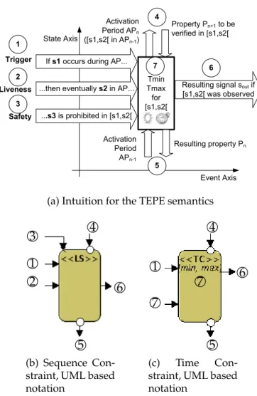
4.2 Intuition and corresponding UML based notations . . . 56
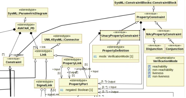
4.3 Excerpt from the TEPE PD Meta Model . . . 57
4.4 Example of a TEPE Parametric Diagram . . . 59
4.5 Temporal Constraint Operator Semantics . . . 66
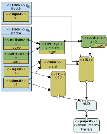
4.6 Microwave oven case study: Block Diagram . . . 70
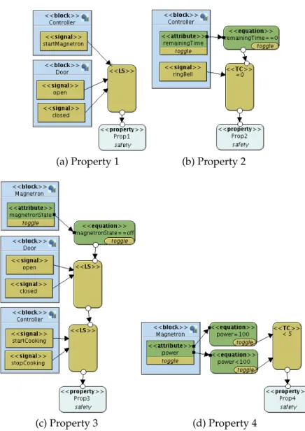
4.7 Microwave oven case study: Properties . . . 73
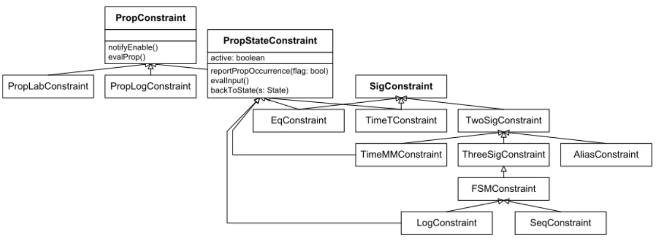
4.8 Architecture of TEPE constraints . . . 74
4.9 Example reachability graph with invoked verifier methods . . . 75
4.10 Functional view of the Sequence constraint . . . 77
5.1 Simulation methodology at a glance . . . 93
5.2 Example of transaction truncation due to synchronization . . . 94
5.3 Transaction truncation inside the DE kernel . . . 95
5.4 Example Scenario: Application . . . 96
5.5 Example Scenario: Architecture . . . 96
5.6 Simulator architecture . . . 98
5.7 Example Scenario: Sequence Diagrams . . . 104
5.8 Completion of the Write Command: Sequence Diagram . . . 105
5.9 Simulation time as a function of the average transaction length . . . 108
6.1 Varying Model Coverage in DIPLODOCUS . . . 109
6.2 State Space Exploration Concept . . . 112
6.3 Running example of an Application Model . . . 112
6.4 Cascaded Static Analysis . . . 118
6.5 Example Tasks for Checkpoint Selection . . . 120
6.6 Illustration of the IndeterminismSource interface . . . 122
6.7 Sequence Diagram for state hashing during simulation . . . 124
6.8 Leveraging presented techniques for model checking . . . 126
7.1 TTool toolchain . . . 129
7.2 The Interactive Simulation Window . . . 134
7.3 Simulation results in the form of a reachability graph . . . 136
LIST OF FIGURES
7.5 Tabulated benchmarks obtained from simulation . . . 137
7.6 Interaction of the Frontend and the Simulator within the TTool Framework . . . 137
8.1 Baseband processing architectural overview . . . 141
8.2 802.11p packet . . . 142
8.3 Excerpt from the DIPLODOCUS application model of the 802.11p receiver . . . 143
8.4 DIPLODOCUS Architecture of the 802.11p receiver . . . 146
8.5 Simulation result for two 64QAM (rate34) packets . . . 148
8.6 TEPE properties to be verified . . . 150
Chapter 1
Introduction
Embedded systems are electronic devices whose computing elements are completely encapsulated in the device they control [109]. As opposed to conventional general pur-pose computers, the range of tasks an embedded system should accomplish is clearly defined. Nowadays, complex embedded systems may be integrated on one single chip and are thus referred to as Systems-on-Chip (SoC). SoC comprise a set of communicating electronic components on the one hand and complex software programmable parts on the other hand. SoCs are highly heterogeneous in nature: digital, analog and mixed sig-nal components may be interconnected to form complex systems ranging from mobile hand sets and set top boxes to automotive controllers and feedback control systems for rail cars. Due to recent advances in the field of semiconductor physics, higher integra-tion densities are achieved so that a given piece of silicon accommodates more and more transistors.
To make use of the available resources, the complexity of embedded systems and
Systems-on-Chip has been rapidly increasing [35; 49]. On the one hand, users are demanding products exhibiting sophisticated features that are reliable, easy to use and affordable. On the other hand, the gap increases between integration and designer effi-ciency due to inadequate tools and methodologies. In addition to the rising demand of functionality, time-to-market is an issue of great concern. Hence, developers are facing significant difficulties due to an exponentially raising complexity. It becomes more and more unlikely that an optimal design represents an intuitive solution, thus the experi-ence of the designer may not lead him/her to optimal designs with respect to functional and non-functional requirements such as performance, size, energy consumption, reli-ability. A whole body of work, including this thesis, is concerned with answering the question how the increasing complexity can be dealt with.
Given a particular functionality and associated requirements, the design space is
con-sidered to encompass functionally equivalent implementation alternatives[40]. Being almost infinitely large at the very beginning of the design flow, the design space should be gradually reduced during the design process by refining the model of the system. The less accurate the specification, the more indeterminism the system model exhibits,
and the larger the design space is. Optimally, a refinement results in a design which optimizes a predefined weight function of requirements.
Although the procedure seems straight forward in theory, pruning the design space
is very difficult to achieve in practice. Experienced designers tend to leverage prior
knowledge and stick to favored designs, which have proved to be well suited for pre-vious products. Thus minor changes on the architecture are applied to derive a new one. While design reuse is a powerful means to cut down development costs of similar products by reducing the design space, it is not that capable when it comes to finding a close to optimal solution for innovative products. Also, platform-oriented design only transfers the problem of pruning the design space from the end-product vendor to the platform supplier. Hence, the essence of the problem remains unchanged and tools that allow for assessing different implementation alternatives for the same functionality are essential.
The analysis of systems at low abstraction levels assures a high degree of accuracy but comes with the downside of being demanding and slow. State-of-the-art simulation techniques operating at RTL, instruction or transaction level are not appropriate for system-level design space exploration for two reasons:
• Only a very limited number of implementation alternatives can be examined due to the high modeling effort and extensive simulation runtime.
• The lack of specification at early design stages may prohibit the construction of detailed models - even if the effort was acceptable.
Thus, the use of abstractions is unavoidable [35] when performing System Level De-sign and should be part of a thoroughly defined modeling methodology. The use of abstractions implies as well that application and architecture concerns are handled in an orthogonal fashion. Indeed, for the sake of reusability, an application model should not need to be rewritten when being experimented on different platforms. This policy is known as the Y-Chart approach [77] and widely used in the landscape of System Level Design Space exploration.
1.1
Problem Statement
The work presented in the scope of this thesis advocates techniques to alleviate design
tasks at early design stages. In that context, the previous section has already pointed out the need for abstractions. We will now have a closer look at the two main types of abstraction, yielding either the functional aspect or the timing aspect of a system. Consequently, two orthogonal views on the system intended for design are prevalent. On the one hand, the designer relies on purely functional, untimed models to examine especially intricate algorithmic parts of the application. For example, if the suitability of a Quadrature amplitude modulation (QAM) decoder is to be looked into, the expected
outcome of the analysis is whether or not the decoder is able to reconstruct the original sequence of samples for arbitrary signals. The availability of the samples at the right time is taken for granted as the provisioning of the decoder with data is abstracted away. Functional correctness is the only concern at this stage. In the domain of signal process-ing and control engineerprocess-ing, mathematical tools such as Matlab have proven their value for fast prototyping.
On the other hand, it is of utmost importance to have a global view of the interplay of system components. Thereby, attention is consequently drawn to timing and perfor-mance allowing functionality to be extensively abstracted. As a consequence, the bird’s eye view on a system aids the developer to arrange and dimension components and communication infrastructure in a way that non-functional constraints are met. To get back to the QAM decoder example, the goal would be to figure out which implemen-tations guarantee that the decoder never runs out of input samples and that the output samples arrive on time at their destination. In that case, the internal computations can be abstracted to symbolic instructions as merely the I/O behavior is of interest in this analysis. This directly leads to the notion of non-functional performance models this work is mainly concerned with.
The contributions of this thesis were made in the context of the DIPLODOCUS frame-work, embracing a UML profile, a methodology and related tooling. It is especially suited for reasoning about abstract (in terms of functionality), control dominated per-formance models of today’s SoC. The framework complements the initially presented fully functional, but untimed models. Also in domains traditionally relying on untimed models, the interplay of various (signal) processing routines is getting more and more sophisticated and needs to be orchestrated by control-centric algorithms. Despite this increasing need for an adequate tooling, state-of-the-art environments of academia and industry are often hampered by the following shortcomings:
• Application (functionality) and architecture (platform) issues are not handled in an orthogonal fashion [60] to speed up HW/SW partitioning.
• Emphasis is exclusively put on either simulation or on formal methods. • A trade-off between these two extreme cases of verification is not provided. • Abstractions are not fully leveraged to perform fast simulation.
• Performance is the only concern; control flow cannot be modeled/verified.
• The methodology does not feature a modeling standard that enforces abstractions (such as UML).
• Details of underlying algorithms must be provided in the form of source code in order to execute the model.
• After model transformation to an executable counterpart, debug information is not back-propagated to the original model.
• The level of abstraction of the language used to express functional properties does not match the level of abstraction of the system model (Example: system model in UML, verification language is CTL).
Some of the aforementioned downsides have been remedied in the context of research prior to this thesis. In the next section, the objectives of this work are surveyed.
1.2
Objectives and Contributions
This thesis is devoted to the enhancement of an existing Design Space Exploration en-vironment which is introduced in Chapter2. Application functionality and architecture are modeled by means of the previously introduced UML profile DIPLODOCUS. The latter is very capable when it comes to modeling complex systems as it introduces data and functional abstractions. DIPLODOCUS is supported by the open source toolkit TTool that, prior to this work, was equipped with modeling features to draw diagrams, a rudimentary simulation engine, and an automated model transformation to the for-mal languages LOTOS and UPPAAL. The main contributions were made in the field of simulation, coverage enhancement of models, expression of functional properties and in the optimization of the design flow:
• An efficient simulation and validation strategy was conceived to complement the formal capabilities of the framework. The novel simulation algorithm takes heavily advantage of the properties of the application model with regards to granularity and abstractions. An execution semantics for DIPLODOCUS operators has been defined which is leveraged in simulation and matches the abstractions inherent to the profile.
• Attention was devoted to finding a compromise between the limited coverage
of conventional simulation and exhaustive formal verification. To extend the coverage of simulation, an algorithm is proposed which statically analyzes DI-PLODOCUS applications and identifies the set of significant state variables at a given point in the application. Methods are presented to exploit results of the static analysis during simulation with the objective to examine several execution branches. In case recurring system states are encountered, simulation of partic-ular branches may be abandoned. With respect to conventional model checking techniques, the coverage of the application model can be varied and constraints of the architecture are taken into account. This considerably limits the state space ex-plosion problem which is encountered when model checking application models alone.
• Verification is often hampered by the obligation to rely on completely different languages than those used for system modeling. For example, verification of a
UML system model should be feasible within the same environment in UML. To address this issue, the verification language TEPE is introduced, a graphical TEmporal Property Expression language based on SysML parametric diagrams. TEPE enriches the expressiveness of other well-established property languages in particular with the notion of physical time, easy to express logical and sequential properties and highly composable operators. Thanks to two dimensional compo-sition, TEPE supports both events and states based formalisms . Besides, TEPE is endowed with a formal semantics which is also part of the contributions of this work.
• The design flow has been optimized in the sense that the user does not need to refer
to the executable model for debugging purposes. Construction, debugging, and verification can henceforth be seamlessly accomplished in the same environment, using the same language, without having to write a single line of code.
• Last but not least, this thesis also comprises an extensive practical part. A prototype has been developed which showcases the above mentioned concepts.
1.3
Outline
This remainder of this thesis is structured in 8 main chapters:
• Chapter2puts this thesis into the context of research carried out at our laboratory. The objective is to make the reader familiar with the DIPLODOCUS framework so as to ease the understanding of subsequent chapters. Furthermore, a clear boundary is drawn between existing elements of the framework prior to this thesis, and enhancements being part of the contributions.
• Chapter3positions the contributions in the landscape of related work on frame-works for System Level Performance Analysis attempts to speed up simulation, verification languages as well as visualization capabilities of development envi-ronments. A classification and a thorough analysisof a considerable body of work motivates efforts and contributions subsequent chapter elaborate on. Finally, an overview of widely used Models Of Computation (MoC) is given to have a frame-work for presenting the DIPLODOCUS MoC in5.4.
• Chapter4presents the verification language TEPE, both intuitively and formally and justifies our decision to build the language upon SysML parametric diagrams. It surveys the SysML AVATAR profile for embedded systems, in the context of which TEPE was initially developed. After exemplifying the use of TEPE with some properties, light is shed on the integration of TEPE into DIPLODOCUS. At
the end of Chapter4,5and6, the interested reader may get some practical insights into implementation issues in the corresponding sections.
• Chapter5covers the simulation semantics of DIPLODOCUS, the algorithm used to simulate DIPLODOCUS models and it elaborates on design decisions such as the use of C++ instead of SystemC. Furthermore, information on the automated model transformation of a UML model to its C++ counterpart are provided. • Chapter6exposes the methodology to enhance coverage of conventional
simula-tion based on static analysis and model checking techniques.
• Chapter 7 is concerned with practical matters regarding the Tooling which are however of importance to make the theoretical contributions applicable in practice. • Chapter8discusses a case study performed in the field of digital signal processing
with the objective to demonstrate the applicability of the concepts.
• Chapter 9 concludes the thesis with an outlook on future research and finally summarizes the contributions and publications.
Chapter 2
The DIPLODOCUS environment for
Design Space Exploration
2.1
Introduction
This Chapter defines the context of this work, which is System Level Design Space Exploration and introduces the methodology developed at our laboratory. As stated in the previous chapter, the contributions highlighted in Chapters4, 5,6, 7were made within the modeling framework called DIPLODOCUS [14; 129]. Section 2.6 clearly distinguishes contributions from existing elements of the framework prior to this thesis. DIPLODOCUS is a UML profile targeting the design of System-on-Chip at a high level of abstraction. A profile customizes UML [91] for a given domain, using UML extension capabilities. This practice has the major advantage that the introduced language does not have to reinvent the wheel in terms of syntax. Instead, predefined UML primitives are reused and are assigned a user defined semantics. Moreover, a UML profile is usually accompanied by a methodology so as to guide the user in his modeling efforts. Recent history has shown that the acceptance of profiles hinges with adequate tool support. Therefore, DIPLODOCUS is supported by a dedicated toolkit called TTool [16]. Section
2.4justifies the usage of DIPLODOCUS with respect to the MARTE [93] profile, which is increasingly gaining attention both from users and tool vendors. Section2.5gives some insight into approaches to fine-tune high level models to improve their accuracy.
2.2
Design Space Exploration
Design Space Exploration (DSE) is the process of assessing viable implementation alter-natives providing a defined set of functions with respect to non-functional metrics such as performance, area, power consumption, heat dissipation, etc. By definition, only solutions complying to functional constraints constitute the design space. That means DSE is linked to the process of further constraining a correct and properly defined set of functions by for example binding them to particular processing units. Throughout
the following chapters, we will be concerned with System Level DSE also referred to as hardware software partitioning (the decision whether to implement a function in hardware or in software). However, it should be emphasized that DSE is of course not limited to that specific domain. DSE is similarly applied in other contexts and at different stages of the design flow of SoCs:
• Evaluation of several pipeline based architectures for Application Specific Inte-grated Processors (ASIPs), most efficiently carried out by means of architecture description languages such as LISA [10;130]
• Analysis of memory hierarchies and caches in particular to match the demand for data accesses [99;118]
• Assessment of bus and interconnect architectures in general with the objective to minimize contention [61;72;73;94;133]
• Trading off delay and area in logic synthesis
Indeed, DSE originates from logic synthesis where the performance of a circuit improves at the expense of an increased silicon area [40], provided that functions exhibit a suf-ficient degree of parallelism. In general, the design parameters span the design space and a variation of design parameters is tantamount to moving through this space. An evaluation of a single design point reveals whether the given requirements are met or the space has to be explored further. Obviously, the whole design space has to be explored in general to spot optimal solutions if no specific knowledge of the problem domain is available. In case an exhaustive search is too costly in terms of execution time or memory consumption, heuristics may be incorporated to prune the design space. Often, covering the whole design space is not feasible due to its sheer size. Nowadays, algorithms are capable of leveraging the knowledge of encountered design points in order to direct the search in an intelligent way. Pareto optimal algorithms for instance yield design points where an improvement of an objective inevitably leads to a degradation of another. However, an automated exploration of the design space is often restricted to a particular family of architectures or is otherwise constrained.
When exploration tasks are performed at system level, abstractions on either data or control flow are necessary to keep complexity within reasonable limits. The Y-Chart approach [60] enables the designer to address separately functionality, architecture and mapping issues. Applications are defined according to an underlying model of compu-tation which captures important properties with respect to a specific problem domain. Architecture models mimic a concrete hardware component or rather stand for a whole family of components. Generic components normally expose parameters to the user which have to be well configured in order to model the desired behavior. A mapping stage binds functional entities to architecture building blocks. The subsequent eval-uation stage may require model transformations (synthesis steps, compilations, code
adaptations) of the inputs models (Kahn Process Networks, Activity Diagrams,...) to executable representations (for example C++, SystemC code). After having carried out simulation, formal verification or static analysis, the designer has to validate the results against the requirements. Further iterations on the involved models may be necessary to obtain acceptable results.
2.3
Methodology
The UML-based DIPLODOCUS methodology for system Design Space Exploration (DSE) is depicted in Figure2.1. It obliges the user to adhere to the Y-Chart approach [60] which has been extensively discussed in literature. In short it states that if application (functional view) and architecture (platform view) are handled in an orthogonal fashion, the burden of experimenting with several design points is considerably alleviated. The Y-Chart approach is thus very capable when it comes to DSE, where an application is to be assessed with different architecture constraints.
The design flow embraces the following three steps:
1. Applications are first described as a network of abstract communicating tasks using a UML class diagram or a component diagram. This is the static view of the application. One behavioral description per task must be supplied in terms of a UML Activity Diagram.
2. Targeted architectures are modeled independently from applications as a set of interconnected generic hardware nodes. A set of parameters permits to calibrate components for their application area. UML nodes were defined to model HW elements (e.g. CPUs, buses, memories, hardware accelerators, bridges).
3. A mapping process defines how application tasks are bound to execution entities and similarly how abstract communication channels between tasks are bound to communication and storage devices.
Within a SoC design flow, DSE is supposed to be carried out at a very early stage. Hence, the main DIPLODOCUS objective is to help designers to spot a suitable hardware architecture even if algorithmic details have not yet been stipulated thoroughly. To achieve this, DIPLODOCUS relies (i) on simulation and formal proof techniques, both at application and mapping level, and (ii) on application models clearly separated from architecture models. Depending on the respective algorithm, simulation speed may benefit from the high abstraction level of both application and architecture models, as compared to simulations usually performed at lower abstraction levels (e.g. TLM level, RTL level, etc.). Additionally, formal analysis techniques may be applied before and after mapping. So far, DSE is not automated in the sense that simulation results and constraints drive modifications on the architecture. However, there have been various efforts in that field [25;42] which could successfully be leveraged for that purpose.
Architecture Application
Mapping
Constraints Simulation Formal verification
Figure 2.1: The Y-Chart approach and DIPLODOCUS
2.3.1
Application model
An application model is the description of functions to be performed by the targeted SoC. Data-dependent decisions are abstracted by means of indeterministic operators. An application model may give rise to several execution traces due to its inherent indeterminism and the potentially undefined partial order of concurrent actions. At ap-plication modeling level, computations and communication transactions are accounted for by abstract cost operators. The time it takes to process the latter can only be resolved with the aid of parameters annotated to the architecture model. Abstract cost operators entail two kinds of abstractions which reflect the degree of uncertainty inherent to early design stages:
• Data abstraction: Only the amount of transferred data is taken into account, not the data itself.
• Functional abstraction: Algorithmic details are abstracted by means of their sym-bolic cost operators.
As stated before, functions are modeled as a set of abstract tasks described within UML class diagrams. Task behavior is expressed using UML activity diagrams that are built upon the following operators: control flow and variable manipulation operators (loops, tests, assignments, etc.), communication operators (reading/writing abstract data samples in channels, sending/receiving events and requests), and computational cost operators. This section briefly describes a subset of the aforementioned operators as well as their semantics and provides definitions for Channels, Events and Requests:
• Channels are characterized by a point-to-point unidirectional communication be-tween two tasks. Three Channel types exist:
– Blocking Read/Non Blocking Write (BR-NBW)
– Non Blocking Read/Non Blocking Write (NBR-NBW)
• Events are characterized by a point-to-point unidirectional asynchronous com-munication between two tasks. Events are stored in an intermediate FIFO queue which may be finite or infinite. In case of an infinite queue, incoming events are never lost. When adding an event to a finite FIFO, the incoming event may be discarded or the event that arrived earliest may be dropped if the FIFO is full. Thus, a single element queue may be used to model hardware interrupts. In tasks, events can be sent (Send Event), received (Wait Event) and tested for their presence in a queue (Notified).
• Requests are characterized by a multi-point to one point unidirectional asyn-chronous communication between tasks. A unique infinite FIFO between senders and the receiver is used to store all incoming requests. Consequently, a request cannot be lost.
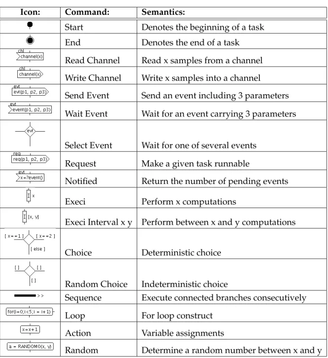
As some of the constituting operators of Activity Diagrams are referred to in later sec-tions, a brief survey is provided which is not meant to be exhaustive (see Table2.1).
2.3.2
Architecture model
A DIPLODOCUS architecture is built upon the following parameterized hardware nodes:
• Computation nodes: Typically, an abstract CPU model merges both the function-ality of the hardware component and its operating system. The behavior of a CPU model can be customized by the following parameters (amongst others): data size, pipeline size, cache miss ratio, number of cores and scheduling algorithm.
• Communication nodes: A communication node is either a bus or a bridge. The bus model exhibits the following parameters: data size, latency, number of channels and scheduling policy. Note that connectors established during the mapping stage are supposed to interconnect a hardware node - except for buses - with a bus. A connector may be annotated by a priority if the respective bus has a priority-based scheduling policy.
• Storage nodes: Memories are parameterized with two measures: latency and data size.
• DMAs: So far, DMAs are represented with an adequately parameterized CPUs and a dedicated task mapped onto it.
A DIPLODOCUS architecture is modeled in terms of a UML deployment diagram where DIPLODOCUS links and nodes have their own UML stereotype.
Icon: Command: Semantics:
Start Denotes the beginning of a task
End Denotes the end of a task
Read Channel Read x samples from a channel
Write Channel Write x samples into a channel
Send Event Send an event including 3 parameters
Wait Event Wait for an event carrying 3 parameters
Select Event Wait for one of several events
Request Make a given task runnable
Notified Return the number of pending events
Execi Perform x computations
Execi Interval x y Perform between x and y computations
Choice Deterministic choice
Random Choice Indeterministic choice
Sequence Execute connected branches consecutively
Loop For loop construct
Action Variable assignments
Random Determine a random number between x and y
2.3.3
Mapping
A DIPLODOCUS mapping describes the association of application elements - i.e. tasks, channels, requests and events - and hardware nodes. Thereby the following rules apply: • Abstract tasks must be mapped on exactly one computation node. This is not
restrictive as the node may support concurrency (e.g. multi-core CPUs).
• Abstract communication entities must be mapped on communication and storage nodes. A channel is usually mapped on n buses, n-1 bridges and exactly one storage element. Furthermore, all connected communication links have to form a continuous path without loops.
Depending on the mapping semantics, additional parameters may be of interest. For example, when mapping a task on a CPU node having a priority-based scheduling pol-icy, task priorities have to be defined.
The mapping stage is carried out based on previously created DIPLODOCUS architec-ture diagrams: artifacts representing tasks and channels are simply bound to hardware components in a drag and drop fashion. Post-mapping specifications contain less traces than pre-mapping specifications since a mapping is intended to resolve shared resource allocations. In contrast, the application model alone does not stipulate any temporal order of concurrent actions, apart from causality constraints due to synchronization. Moreover, traces obtained after mapping are supposed to be a subset of traces obtained before mapping.
2.3.4
Nomenclature
Several notions are used abundantly throughout this thesis and therefore need some closer attention. A formal definition of DIPLODOCUS operators and related notions is out of scope of this work and can be found in [55].
• Command and Operator are used as synonyms and refer to the building blocks of an Activity Diagram. They describe the behavior of DIPLODOCUS tasks. The operators relevant for this work are depicted in Table2.1.
• The execution semantics of DIPLODOCUS tasks implies that commands are not considered as atomic. Commands can be split into smaller portions to satisfy application and architecture semantics. This portion is henceforth referred to as
Transaction. As an example, an Execi 10 command may be broken down into two transactions of length 8 and 2 respectively.
• The separation of concerns demands for different units of measurement for com-plexity and time. At application level, comcom-plexity is specified in terms of Execi units or data samples and is called (virtual) length. As soon as a transaction is bound to HW devices, its physical duration may be computed as a function of its
(virtual) length and device parameters. The latter measure is therefore referred to as duration.
• The notion of ”Channel“ appears in two contexts in this work: first a Channel denotes a means of communication between two DIPLODOCUS tasks. Second, if a bus may handle several data transfers concurrently, it is said to provide several channels. The intended meaning should become clear from the context.
• Unfortunately, the notion of Event is overly stressed in different communities. First, in DIPLODOCUS it stands for a means of synchronization among tasks. Second, it is used in a broader sense to denote a transition from one system state to another. The latter meaning applies in the context of Models of Computation (cf. Section3.2) and the simulation kernel (cf. Section5.6.3).
• In DIPLODOCUS, behavior may be captured with a class diagram or likewise with a component diagram. Classes and components share the same semantics; they are defined as concurrent functional entities with their own control flow. In the following, both notions are referred to as tasks to abstract from the underlying diagram type.
2.4
A word on MARTE
Having gained an insight into DIPLODOCUS, the reader may ask the legitimate ques-tion why we did not rely on the MARTE [93] profile. MARTE constitutes an extension of the UML standard and its major concerns are specification, design, verification and val-idation stages of real time and embedded system development. Packages are devoted to resource modeling, non-functional properties, value constraints, hardware/software resource modeling, allocation modeling and schedulability analysis. The profile thus replaces the UML Profile for Schedulability, Performance and Time. MARTE seeks to establish a common ground for reasoning about systems, by standardizing a particular syntax. This policy enables designer to exchange models internally and between third parties in a standard format. However, MARTE does not stipulate any particular se-mantics or methodology; this is left to the user or a methodology provider respectively. MARTE allows to annotate models with additional information which can be leveraged for performance and schedulability analysis.
Even if the contributions of this thesis are exemplified with the aid of the DIPLODOCUS framework, they apply just as well to any other language exhibiting the same semantics, be it a textual form, MARTE, or others. The syntactical structure of the language has no impact on verification, simulation or coverage procedures presented herein. Nothing prevents the user from modeling the application in terms of MARTE blocks stereotyped as schedulable resources, to make use of the MARTE Hardware Resource Model in archi-tecture diagrams, to bind schedulers (defined with the MARTE GaExecHost stereotype) to components using the MARTE allocate stereotype, etc.
In any case, MARTE Activity Diagrams would have to be enriched with the operators described in2.3.1.
2.5
Model calibration
Regardless of the formalism or UML profile used, the major goal of high level models is to minimize the modeling effort and to reach a high execution speed. However, the obtained performance figures will not lead the designer to the right design decisions if they are too far from the actual system behavior. Therefore, an issue of great concern is to yield sufficiently insightful performance estimations despite the applied abstrac-tions. To achieve this, the parameters exposed by abstract models have to be fine-tuned best possible to the respective circumstances. In that context, two use cases can be discriminated:
• The system itself or a similar one has already been refined so that low level models (source code for software, RTL for hardware) are available. High level modeling in that case constitutes an efficient way to extend the scope of the analysis from component to system level and to improve simulation speed significantly.
• The system under design is novel so that no suitable low level model is at hand. High level modeling is the only way to get some first insights into the performance. In literature [70;103], four approaches for calibration are prevalent:
1. Deducing the number of operations from a purely algorithmic description: there-fore, from a representation in pseudo-code, Matlab, or other high level domain specific languages the number of instructions (different types of operations, mem-ory accesses, etc.) is calculated
2. Extracting data from measurements or traces of similar existing systems: the first step would consist in separating the individual contributions to system load, i.e. the different applications. Thereafter, the utilization of a CPU would be measured separately for each application and the results merged as a function of the particular use-case. The last step aims at differentiating memory accesses from processing instructions based on their assumed probability of occurrence.
3. Inferring the workload from low level models, for instance source code: The simplest approach would just entail cross-compiling an application for the tar-get platform and counting execution and memory access instructions. However, provided that the high level model reflects control flow like DIPLODOCUS, the challenge to match assembly instructions with high level control structures has to be dealt with. In the presence of sophisticated optimization features of today’s compilers, it is obvious that this is not a trivial exercise (cf. [116;128]).
4. Rather than relying on tabulated values for calibration, so called on-line calibra-tion could dynamically compute the exact values at simulacalibra-tion run time. This is tantamount to integrating models of heterogeneous abstraction levels in order to trade off simulation performance against increased accuracy. As this method is currently not foreseen in DIPLODOCUS, it is not elaborated in further detail. All hardware dependent measures obtained with the aforementioned strategies would of course be annotated to the DIPLODOCUS architecture model. To make sure platform-independence is respected, the DIPLODOCUS application model merely comprises fig-ures characterizing the complexity of an algorithm in terms of instructions of particular type (floating point instruction, FFT, etc.). In the further course of this thesis, the devel-oper is assumed to have an adequate strategy for model calibration at hand.
In the following, several questions regarding model calibration and best practices of DIPLODOCUS modeling will be answered in an FAQ manner.
Data abstraction: boon or bane?
It should be reemphasized that data-dependent behavior of the application has to be expressed in terms of random operators. That is, a stochastic model of data hazards has to be embedded into the application model. However, this effort is not particular to our methodology, neither it is to a high level of abstraction. Whenever a system is loaded with data-dependent tasks, the designer is obliged to come up with a statistical model of the data to be processed. Only with that model, it is possible to avoid overdimensioning the system for the worst case. The statistical model gives the designer the confidence that an architectural trade-off delivers an acceptable performance with a known proba-bility.
Which granularity has to be applied for data exchanges (Read/Write operators for channels)?
Basically, all commands manipulating data could in theory entail a Read/Write trans-action on a bus. Even if one considers a simple command such as an assignment, it is not guaranteed that the variables referred to are held in cache. One can discern two main types of data: on the one hand data related to control flow (loop variables, flags, ...) and on the other hand input or output data of an algorithm. The fast discrete cosine transform algorithm for example exhibits two consecutive loops containing the compu-tation of frequency coefficients as a function of the given input samples. Control flow merely relies on the loop variables. Fortunately, the usage of control flow variables often satisfies the temporal and the locality criterion of data caches. Furthermore, the amount of control data is often neglectable as compared to the input and output values. For these reasons, control data transfer is not modeled with DIPLODOCUS channel oper-ators. The model of the DCT algorithm is thus reduced to reading the input samples, executing the main algorithm and writing back the output frequencies to memory.
What about the detailedness of an algorithm?
The algorithmic model should cover branches that differ significantly in terms of pro-cessing time. This means that the model should not reflect if statements spanning only a few cycles. In this case, an average value of cycles should be applied in favor of sim-ulation speed (an Execi Interval operator could be used as well). Adequate statistical models should be provided which guarantee a realistic behavior in spite of the lack of "real input data". DIPLODOCUS Action and Choice commands can be used for the necessary computations of Exec units and to direct the control flow.
Which granularity of partial order to choose for read, execute and write operators?
The most simplistic model of an application would just consist of a read (for input data), an Execi operator and a Write operator (for output data). The other extreme case would be to spread the three operations more or less uniformly across the task, enriched with control flow operators. The simulation algorithm presented in this thesis (Chapter 5) is able to take advantage of long transactions in order to process more clock cycles per time unit. Thus, simulation performance benefits from a coarse grained model to the detriment of simulation accuracy. Consequently, there is no silver bullet to address this problem, as its solution highly depends on the particular simulation objective.
2.6
Putting Contributions into context
Modeling
Formal Code
Generator C++ Code Generator
_______ _______ _______ UPPAAL _______ _______ _______ LOTOS _______ _______ _______ LOTOS _______ _______ _______ Executable Model (C++) Verification Bisimulation
DIPLODOCUS Application DIPLODOCUS Architecture
DIPLODOCUS Mapping Requirement Diagram TEPE-formalized Requirements Formal Code Generator Feedback to UML Models
Static Simulation & Verification Library
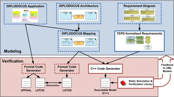
Figure 2.2: DIPLODOCUS design flow
The open-source toolkit TTool [16] supports several UML2/ SysML profiles, in particular DIPLODOCUS [11], AVATAR [65], TURTLE [13], CTTool [8] and Network Calculus [15].
TTool offers UML model editing facilities as well as press-button approaches for formal verification. TTool and its profiles have proven their value in several projects conducted with academic and industrial partners.
Formal verification can be conducted on the application model alone or on the mapped model, embracing an application and an architecture (cf. ”Formal Code Generator“ labels in Figure2.2). TTool is interfaced to verification tools by means of the intermediate formal languages LOTOS and UPPAAL. However, these languages are transparent to the user thanks to automated model transformations. TTool offers a user-friendly interface to check simple properties such as liveness and reachability (e.g., with UPPAAL) of UML operators. A reachability graph may also be transformed into a Labeled Transition System, a structure for which CADP [38] implements minimization techniques based on trace or observational equivalences just to mention a few. Formal techniques may further be leveraged to carry out formal Design Space Exploration of Systems-On-Chip [62].
In Figure2.2, the achievements of this work are marked with a white background and continuous borders, while existing elements are marked with a dashed border. Prior to this thesis, merely liveness and reachability of DIPLODOCUS operators could be checked at the push of a button. To this end, the UPPAAL verifier was invoked with the corresponding CTL formula. When it came to more complicated and user defined properties, they could only be expressed by means of SysML requirement diagrams in an informal way, namely in plain text. The only way to formalize them was to provide CTL formulas to TTool and which were simply forwarded to the model checker. This work eliminates this rupture of the design flow by proposing a UML-based, formal verification language suited for the abstraction level of DIPLODOCUS (see Chapter4). Moreover, a fast simulation engine was developed [63] which provides visual feed-back to UML models [64] (see Chapter 7) and thus allows for debugging and verification directly in the source model. Chapter5elaborates on the simulation algorithm, whereas pivotal techniques permitting the extension of the simulation coverage are discussed in Chapter6.
2.7
Conclusions
In summary, this chapter made the reader familiar with the high level Design Space Exploration Environment DIPLODOCUS, the homonymous profile, its methodology and operators. It is based on the Y-Chart approach acknowledging the need for separate models for application and architecture. That way, the developer may experiment very efficiently with several possible implementations for a given set of functions. It has been stated that the profile MARTE could also be used to express the semantics of DIPLODOCUS, if Activity Diagrams were enriched with some additional operators. The contributions of this thesis are however not impacted by the concrete syntax of the modeling language, as long as the semantics is respected. Lastly, this chapter dealt with the crucial issue of parameterizing high level models so as to improve their accuracy.
Algorithmic descriptions, low level model and knowledge of the field of application may be leveraged for that purpose.
After the existing environment and the intended enhancements have been presented, the next chapter justifies the latter by examining related work in the field of system level modeling, simulation and verification of Systems-on-Chip.
Chapter 3
Approaches for System Level DSE and
Verification
3.1
Introduction
This Chapter surveys efforts to verify non-functional and functional properties of Systems-on-Chip (SoC) early in their design flow. Section3.2 paves the way for the analysis of related work and the DIPLODOCUS simulation semantics (section5.4). The section cov-ers the common ground of all modeling efforts, namely Models of Computation (MoCs). Section3.4focuses on System Level Design Space Exploration (DSE) where models are tailored towards performance aspects and are not necessarily functional. In that context, approaches can be roughly classified into three categories, to which separate sections are devoted: formal/static approaches (Section 3.4.1), simulation centric approaches (Section 3.4.3) and hybrid variants (Section 3.4.4). For a more thorough classification of approaches please refer to section 3.3. Formal and simulation based environments are contrasted with each other as well as approaches targeting whole systems or solely communication architectures (Section3.4.5). Depending on their methodology and the underlying MoC, frameworks may be restricted to a particular range of applications (such as signal processing applications) and attain a different coverage of the design space. Simulation as a verification method plays a pivotal role in this thesis. To that end, methods aiming at speeding up traditional simulation techniques are surveyed as well in Section 3.4.6. Section 3.5 justifies our property expression language TEPE with respect to popular approaches in that domain. To acknowledge the importance of tooling for the acceptance of a methodology, TTool is related to state of the art UML modeling environments embracing visualization features (see Section3.6).
3.2
Models of Computation
As this section demonstrates, Models of Computation play a pivotal role in system modeling and verification. In later sections, related approaches for DSE are compared
Models of Computation Abstraction Level Timing Concurrency Communication Data Structures Synchronicity Synchronous/ Asynchronous Algorithmic Abstractions
Global / Local Timing Process Definition
Partial / Total order Continuous/Discrete
Figure 3.1: Classification of Models of Computation
with respect to the underlying MoC (amongst other criteria such as the capabilities of verification features). For this reason, this section paves the way for the analysis of related work by providing definitions and examples of MoCs. Moreover, general properties of MoCs are related to the DIPLODOCUS profile in particular. DIPLODOCUS semantics of application models was formally defined and justified prior to this work in [11;14]. However, the semantics of hardware components and mapping leaves room for different interpretations. Section5.4intents to clarify simulation semantics and justifies the decisions.
In DIPLODOCUS . . . Engineering as a discipline is heavily tied to the
pro-cess of modeling, which refers to solely taking into ac-count relevant properties and parts of a system under design. Details that do not impact design decisions at the current stage can be abstracted away (com-pare Section3.4.3.1). The art of modeling amounts to discriminating the relevant from the irrelevant with respect to the expected outcomes, be it performance figures, compliance to properties, etc.
. . . data abstraction, indetermin-istic operators and symbolic oper-ations attempt to abstract system behavior while preserving perfor-mance relevant properties to a large extent.
As soon as digital electronic systems come into play, basic atomic operations of the system are referred to as computations.
. . . transactions of length one (1 Execi unit, 1 data sample) are con-sidered as atomic actions.
A MoC specifies the set of allowable operations and may account for their respective costs, the state change provoked in the system, or both. Thereby, MoCs may abstract from the underlying physical de-tails to capture only features relevant to the problem.
. . . there are mainly two allow-able operations: control flow re-lated ones taking no time (Choice, Action, etc.), and operations with which are associated a cost (Execi, Write, Read, etc.)
This suggests that the choice of an adequate MoC highly depends on the nature of the application to be modeled and the aspects to be investigated. For instance, control flow issues of a video player ap-plication could be expressed in terms of Petri nets, whereas the signal processing part is analyzed by means of synchronous dataflow models.
. . . emphasis is placed on per-formance modeling. However, ongoing research investigates to what extent and under which con-ditions functional properties are preserved with respect to more
de-tailed models. DIPLODOCUS
is control flow centric and there-fore less suited for modeling data flow systems which are always as-sumed to be in a (single) steady state.
According to [35] and [74], a MoC can be character-ized by the following elements:
An event comprising a tag (for example the time of occurrence) and a value (for example an ID denot-ing the nature of the event). Timed MoCs impose the order of tags, untimed MoCs may merely estab-lish a causal/partial order. Events often trigger the transition to a new system state.
. . . application models are un-timed and thus merely impose a causal order on events (not to be confused with DIPLODOCUS events). Only after the mapping stage the timing of events can be resolved.
A process is considered as a set of possible behaviors relating input signals to output signals. The MoC determines the character and the building blocks of the processes the application is made of.
. . . the notion of”task“ corre-sponds to a ”process“ in the MoC terminology.
The state of a system makes the system’s history ir-relevant or in other words the system cannot distin-guish between histories which lead to the same state. The state of the system embraces all pieces of infor-mation needed to determine the responses to future inputs.
. . . the state space is spanned by local variables of tasks, the cur-rent position within a task and the state of all synchronization primitives. The architecture can be seen as an instrument to limit the partial order of the application, which does not necessarily extend the state space.