HAL Id: tel-01355188
https://pastel.archives-ouvertes.fr/tel-01355188
Submitted on 22 Aug 2016HAL is a multi-disciplinary open access archive for the deposit and dissemination of sci-entific research documents, whether they are pub-lished or not. The documents may come from teaching and research institutions in France or abroad, or from public or private research centers.
L’archive ouverte pluridisciplinaire HAL, est destinée au dépôt et à la diffusion de documents scientifiques de niveau recherche, publiés ou non, émanant des établissements d’enseignement et de recherche français ou étrangers, des laboratoires publics ou privés.
Raphaël Riquier
To cite this version:
Raphaël Riquier. Magnetic field in laser plasmas : non-local electron transport and reconnection. Plasma Physics [physics.plasm-ph]. Université Paris Saclay (COmUE), 2016. English. �NNT : 2016SACLX004�. �tel-01355188�
T
HÈSE
DE
D
OCTORAT
DE
L
’U
NIVERSITÉ
P
ARIS
-S
ACLAY
PRÉPARÉE
À
L
’É
COLE
P
OLYTECHNIQUE
ÉCOLE DOCTORALE N°572
Ondes et matières
Spécialité de doctorat : Physique des plasmas
Par
M. Raphaël R
IQUIER
Magnetic field in laser plasmas:
non-local electron transport and reconnection
Thèse présentée et soutenue à Palaiseau, le 28 Janvier 2016 : Composition du Jury :
M. Jean-Marcel RAX Professeur, École Polytechnique Président du Jury
M. Stephano ATZENI Professeur, Università di Roma, La Sapienza Rapporteur M. Robert CAUBLE Directeur de JLF, LLNL Rapporteur
M. Xavier RIBEYRE Ingénieur-chercheur, CEA Examinateur
M. Roch SMETS Maître de conférence, UPMC Examinateur
M. Julien FUCHS Directeur de recherche, CNRS Directeur de thèse M. Alain GRISOLLET Ingénieur-chercheur, CEA Encadrant
Contents
Notations 1
Introduction 3
1 Modeling the heat flux in hydro-radiative simulations 13
1.1 FCI2: A Resistive MHD hydro-radiative code (and more) . . . 14
1.1.1 The physics included in FCI2 . . . 14
1.1.2 Hydrodynamics of a solid foil irradiated by a nanosecond laser pulse 16 1.2 The limited Spitzer-Härm heat flux . . . 18
1.2.1 Kinetic equation . . . 19
1.2.2 P1 system (isotropisation) . . . 20
1.2.3 The Spitzer-Härm heat flux (Maxwellianisation) . . . 22
1.2.4 Limited heat flux . . . 23
1.3 The Braginskii heat flux . . . 25
1.3.1 Linear transport . . . 25
1.3.2 Braginskii’s notation . . . 26
1.3.3 The Righi-Leduc effect . . . 28
1.4 The magneto-hydrodynamic framework . . . 28
1.4.1 Momentum equation, the Laplace (Lorentz) force . . . 29
1.4.2 Energy equation . . . 30
1.4.3 Ohm’s law and B-field induction equation . . . 31
1.4.4 Nernst effect . . . 32
1.5 Modeling the non-local heat flux in FCI2 . . . 34
1.5.1 Presentation of the model . . . 37
1.5.2 B-field – Heat flux coupling strategies . . . 42
1.5.3 Comparison with a Fokker-Planck code: ALADIN . . . 44
1.6 Conclusions . . . 54
1.7 Useful equations . . . 58
2 Experiments 61 2.1 Single laser beam experiments . . . 64
2.1.1 LULI2000 (2008) . . . 65
2.2 Comparison integrated measurements – post-processors . . . 69
2.2.1 Interferometry . . . 70
2.2.2 Polarimetry . . . 78
2.2.3 X-ray pinhole . . . 82
2.2.4 Proton-Radiography . . . 84
2.3 Comparison of the heat flux models with the LULI2000 experiment. . . 100
2.4 Conclusions . . . 105
3 Analysis using FCI2 107 3.1 Magnetic field topology . . . 109
3.1.1 Topology of the magnetic field . . . 109
3.1.2 Source and confinement of the magnetic field . . . 111
3.1.3 Transport regimes . . . 114
3.2 Parametric study of the laser parameters . . . 116
3.2.1 Reference and high energy cases . . . 116
3.2.2 Focal spot : Flat-top and high intensity cases . . . 117
3.2.3 Laser wavelength : 3ω case . . . 118
3.3 Effects of the magnetic field on the interaction . . . 120
3.3.1 Effects on the heat flux . . . 121
3.3.2 Effects on the hydrodynamics . . . 126
3.3.3 Energy balance . . . 131
3.4 Extrapolation to ICF conditions . . . 134
3.4.1 Driving laser : LMJ or NIF quad . . . 134
3.4.2 Full scale ICF experiment . . . 135
3.5 Conclusions . . . 137
4 Reconnection of the magnetic field in high energy density plasmas 139 4.1 State of the art of magnetic reconnection . . . 142
4.1.1 The Sweet-Parker model . . . 143
4.1.2 The magnetic field reconnection in various plasma physics contexts 146 4.1.3 Experimental platforms for the study of reconnection . . . 149
4.2 Motivation for the experiments : study using Heckle . . . 154
4.2.1 Different methods to simulate the reconnection . . . 154
4.2.2 Hall component of the magnetic field . . . 156
4.2.3 Effects of an angle between the irradiation spots . . . 157
4.3 Reconnection experiments using laser driven plasmas . . . 161
4.3.1 Phelix . . . 161
4.3.2 LULI2000 . . . 164
4.3.3 Interpretation of the results . . . 171
4.4 Conclusions . . . 178
Conclusion 181
Bibliography 185
List of Figures 198
Role of the author 199
Notations
Notation Description
Ne electron density
Nc critical density
Te,i electron (resp. ion) temperature
Dt Lagrangian derivative ∂t∂ + (u.∇)
ρ mass density
u fluid velocity
Pe,i electron (resp. ion) pressure
Pmag magnetic pressure
Q heat flux
Ee,i electron (resp. ion) internal energy
νei,ee electron-ion (resp. electron-electron) collision frequency
j electron current density
v electron velocity
e elementary charge
me,i electron (resp. ion) mass
Z atomic number
c speed of light
f electron distribution function
f0 scalar distribution function
f1 vectorial distribution function
fm
0 Maxwellian distribution function h correction to the scalar Maxwellian
y correction to the vectorial Maxwellian
E electric field
B magnetic field
b magnetic field’s direction
KSH Spitzer-Härm diffusion coefficient
C0,1 collisional operators E(v), D (v) Rosenbluth coefficients α, β, κ Braginskii’s coefficients
Notation Description
χ thermal electron magnetization (Hall parameter)
χv velocity dependant electron magnetization (Hall parameter)
βth thermal beta parameter P/Pmag
βkin kinetic beta parameter ρu2/2Pmag
σ electric conductivity η electric resistivity
λei,ee electron-ion (resp. electron-electron) collision mean free path
dE electron stopping length in an electric field
I laser intensity
λL Laser wavelength
Δφ Phase difference
N Optical index
ωpe,i electron(resp. ion) plasma frequency
ωce,i electron (resp. ion) cyclotron frequency
RL Larmor radius
Ma Mach number
Kn Knudsen number
Re Reynolds number
Rm magnetic Reynolds number
VA Alfvén velocity
S Lundquist number
Introduction
Basics of inertial confinement fusion
The principle of inertial confinement fusion (ICF) [1] is to maintain a dense fuel, composed of low mass number nuclei, in a compressed state for a time long enough, such that fusion reactions consume the fuel before it disassembles due to its own pressure. Since the reaction rates depend on the cross-sections between the two fusing ion species, most of the efforts are currently toward the fusion of deuterium (D = 2H) and tritium (T = 3H)
as they present the best cross section �σv�DT in an accessible range of temperature. The
first is an abundant isotope of hydrogen, mostly found in water, while tritium can be produced from lithium irradiated by neutrons, themselves produced by the D-T reaction:
D+ T → 4He(3.5MeV ) + n(14.1MeV ). The goals of ICF are multiple:
• From a societal point of view, it could be a source of energy, if the repetition rate and gain G are high enough to compensate for the efficiency ηD of the energy driver (an
array of nanosecond lasers in the most common approach), the thermal to electrical power conversion efficiency ηth and the fraction f of the output power used to run
the driver. Then, with f = 0.25, ηD = 0.1 and ηth = 0.4, and because of the relation
Gf ηDηth= 1, this leads to a required Gain G > 100 for ICF to be an efficient power
source.
• From a scientific point of view, achieving high gains, in accordance with numerical simulations, is the proof of a good understanding of the many physical processes at play and their modeling. Moreover, investigating the physics at play and the properties of matter in such a state of high energy density is of interest for many branches of science, such as laboratory astrophysics [2, 3]. Finally, the research on high gain ICF experiments is a drive for technological progress, yielding applications in various fields (material processing, laser technologies etc.)
The feasibility of a self-sustained heating through nuclear reactions is characterized by the Lawson criteria, nτc, which represents the required conditions on the confinement. For
example, in a tokamak the plasma’s density n is small (∼ 1015cm−3) but the confinement
time τc is long (> 1 s) [4], while in ICF τc is short (< 100 ps) but n is large (1024 −
1026cm−3) . In fact, in ICF, rather than a confinement time, τ
c represents the time taken
Let us consider a sphere of high pressure fuel of homogeneous density ρ and radius R. The confinement time can be estimated as the time required for a rarefaction wave, traveling at the sound velocity Cs, to reach the center [5]. Let τc(r�) = (R − r�)/Cs be the time at
which the fuel at r� starts it outward motion. The global confinement time is found by
mass averaging over the entire sphere:
τc = ˆ R 0 ρ4πr �2[(R − r�) /C s] dr� ρ(4/3) πR3 = R/4Cs. (0.1)
To estimate the fraction fb of the fuel which is burned before the sphere disassembles, let
first denote nD and nT the number density of deuterium and tritium. The rate at which
the deuterium or tritium are burned is then:
dnD,T/dt= −nDnT �σv�DT,
or considering nD = nT = n/2 with n the total fuel number density:
dn/dt= −�n2/2��σv�DT .
Once integrated over τc, we have:
1/n − 1/n0 = (τc/2) �σv�DT .
Considering the burned fraction fb = 1 − (n/n0), τc = R/4Cs (Eq.0.1) and n0 = ρ/mDT
the initial fuel density, where mDT = 2.5 [amu] leads to:
fb = ρR/ [ρR + β(T )] , with β(T ) = 8mDTCs/�σv�DT. (0.2)
In typical burn conditions, a burned fraction of 1/3 requires a fuel surface density ρR = 3 g/cm2, or for an uncompressed DT fuel (ρ = 0.21 g/cm3), a mass of 2.6 kg. Yet, the
problem is that with 17.6 MeV released per fusion reaction, the total energy output is 2.9 × 10¹⁴ J, i.e. 70 kt of TNT, which is commonly admitted to be too much for a
laboratory experiment.
If we want a lower output, we have to compress the target so that the mass is reduced but keeping ρR constant. For example, compressing the target to 190 g/cm3 gives a mass
Indirect drive ICF
Figure 0.1: (Top) Specific energy
varia-tion in the hot-spot as a funcvaria-tion of space. Pα, Prad, Phyd, Pec, Pic and Pn
refer to the contribution of the α par-ticles, radiations, hydrodynamic, elec-tronic conduction, ion conduction and neutrons.
(Bottom) Position of the maximum re-action rate τα and electronic flux Fe.
From [6].
In laser driven ICF, the best way to achieve a high compression is through a spherical im-plosion, as the density will scale as R3. Yet,
as we ultimately want to heat the fuel us-ing the accumulated kinetic pressure, an ini-tially homogeneous solid sphere of fuel is no more possible. Instead of that, the fuel is formed of a plastic capsule filled with the D-T, which, once cooled down to a few Kelvin, forms a layer of ice inside the capsule enclos-ing a low density gas. The in-flight aspect
ratio (IF AR = R/ΔR) is then a
compro-mise between a thin capsule converging at high velocity and a thick capsule resilient to hydrodynamic instabilities.
The mechanism to accelerate the target is the rocket effect: the outer plastic layer of the pellet is quickly heated, becoming a high pressure plasma which expands outward at high velocity and thus pushes the remain-ing capsule inward, just like a rocket for which the exhaust gases accelerate the pay-load (cryogenic D-T in ICF) as well as the remaining fuel (the plastic ablator).
Upon reaching convergence, the kinetic en-ergy of the D-T fuel accumulated by the
P.dV work is converted into internal energy,
heating a point of the low density fuel to a high temperature, initiating nuclear fusion reactions. The electronic conduction and the α particles produced by the fusion reac-tions then ablate the inner face of the solid fuel, forming a hot-spot of increasing mass. Fig. 0.1(top) shows the different transport processes at play in this hot-spot. Know-ing that the temperature has to stay high
(reaction-diffusion) ongoing, the α-heating has to overcome the cooling of the hot-spot by electron conduction. Note that at some point, volumic heating of the dense D-T fuel by the neutrons reduces the stopping power of the suprathermal ions so much, that they heat the shell deeper than the electronic ablation front (see Fig. 0.1,bottom), leading to a supersonic reaction wave and thus a transition from the deflagration into a detonation (reaction-compression) [6].
As we saw, the principle of ICF is based on the very quick deposition of energy on the target, to compress it using the rocket effect. Different methods have been envisioned to do so, but currently, the use of lasers is the most realistic way. Two schemes are heavily studied: the direct drive and the indirect one. In the first case the lasers are directly irradiating the target, depositing energy at the critical electronic density (Nc =
8.9 × 1021cm−3 for a laser with a wavelength of 0.351 µm1). On the opposite, in the
indirect drive scheme, the capsule is placed in a high Z cavity also called hohlraum which acts like a x-ray oven: the lasers heat the inner face of the cavity’s walls, converting the laser light to soft x-rays [7]. These x-rays are then rapidly absorbed and re-emitted, producing a pseudo black body heating the target with a much better homogeneity than in the direct drive scheme.
To illustrate this particular set-up, a 2D simulation of an indirect drive experiment, using the FCI2 code2, is presented in Fig. 0.2. Looking clockwise: the mass density map (upper
left) shows the capsule which outside is being ablated. It is placed in a rugby shaped [8] gold cavity, filled with a gas to prevent the gold plasma ablated by the lasers (upper right) to reach the capsule: this color-map of absorbed laser power density also puts into light the interface between the gold and the gas, as well as the electronic ablation front (supposed close to the critical density where the laser radiation cannot propagate). The laser energy is then converted to x-rays trapped in the enclosure (lower right), producing a very homogeneous radiative flux which drives the capsule. Finally, the kinetic energy density map (lower left) shows, from the center to the outside: the capsule accelerating inward by the radiatively ablated plastic and the steady electronic ablation front. Note that most of the kinetic energy is located in the imploding capsule.
Self-generated magnetic fields in ICF
Up to now, four years of full scale experiments on the National Ignition Facility (NIF) have remained unsuccessful in terms of overall gain [9], proving that something (either technical or physical) is missing in the modeling, since a gain of more than 10 MJ was
1Reducing the laser wavelength from first (1.053 µm) to third (0.351 µm) harmonic allows for a laser
absorption at a higher density, and thus a better absorption (and better conversion into x-rays for indirect drive).
2FCI2 is a 2D hydroradiative code, developed at CEA for the design and interpretation of laser-plasma
���� ���� ���� ���� ���� ���
Figure 0.2: 2D axi-symmetrical FCI2 simulation of a full scale ICF experiment in
indi-rect drive. (All quantities are shown in log scale, normalized to their maximum) Top Left: mass density.
Top Right : absorbed laser power density Lower Left: kinetic energy density. Lower Right: radiative energy density.
predicted [10] based on Lasnex simulations [11]. For the “technical” issues, heavy 3D simulations of capsule implosions [12] have pointed out that geometric effects (the surface roughness of the capsule, the tent holding it, the tube filling the capsule with D-T, etc) drastically deteriorate the implosion. This thesis is part of another approach, namely the study of physical phenomena, supposed to have little effects on the overall interaction and thus previously neglected.
When the lasers irradiate the inner wall of the cavity, the expanding gold plasma self-generates magnetic field loops of the order of the MegaGauss (1 MG = 100 T ) around the irradiation spots, due to thermo-electric effects [13] i.e. the non-collinear electron density and temperature gradients (see. Fig. 0.3). This induces a magnetization of the plasma that was supposed to be of small importance. Nonetheless, as we will see, this magnetic field is strong enough to drastically alter the heat flux by turning it (Righi-Leduc effect [14]) and reducing the effective range of the fast electron population (relocalization), which carries the heat in the plasma. In return, the magnetic field is transported both by
grad Ne Target
Laser
B-field
grad Te
Figure 0.3: Illustration of the self-generation of the magnetic field in laser-solid
interac-tion.
the plasma motion (frozen in field) and the heat flux (Nernst effect [15]).
While the overall hydrodynamics of an indirect drive experiment is driven by radiations, we observe (as will be detailed in this manuscript) that the model used for the heat flux alters the resulting electron temperature of the plasma filling the cavity, and thus the way the lasers propagate from the laser entrance holes (LEH) to the cavity’s wall. Indeed, the modelization of laser-plasma interactions (LPI), filamentation and energy deposition in the cavity relies on an accurately defined electronic temperature of the filling gas [16].
Figure 0.4: Illustration of the laser irradiation in a former LMJ design (cylinder
hohlraum). From [17].
Moreover, the cavity’s wall being irradiated by multiple close-by laser spots (see Fig. 0.4), numerous magnetic field loops are generated, growing in size and amplitude with the expanding gold plasma bubbles. At some point, the field lines of neighboring loops will be compressed toward each other, leading to a strong gradient of magnetic field, as the field lines are anti-parallel. This is the setup for magnetic reconnection events, where the magnetic field energy is converted back to kinetic energy [18]. Thus, if the reconnection is fast and localized enough, this may lead to inhomogeneities in the x-ray emission from the
gold wall and, ultimately, to asymmetries in the capsule implosion. More generally, the magnetic reconnection is of interest in the study of plasma physics, solar physics (coronal mass ejections, heating of the solar corona etc.), space physics (reconnection between the interplanetary magnetic field and the Earth’s magnetosphere) or laboratory discharge plasma physics.
Structure of the thesis
The goal of the thesis will thus be to investigate the growth and evolution of magnetic fields in ICF plasmas, as well as investigate the reconnection processes that could take place between two neighboring magnetic field structures.
The first chapter of this thesis is dedicated to the presentation of different models of heat flux, starting with the most common one: the flux limited Spitzer-Härm (S-H) [19]. It has been used for decades due to its simplicity, but because of its assumption of a local heat flux (diffusion), it relies on an arbitrary parameter to fit experimental results. In the presence of magnetic field, there exists another approach, the Braginskii treatment [20] that provides numerical fits of the conductivity tensors to model the interplay between the local heat flux and the magnetic field transport.
In laser generated plasmas, the validity of the local heat flux fails as, in the electronic con-duction zone, the mean free path of the heat-carrying electrons (traveling at 3-4 times the thermal velocity, while the mean free path is function of v4) is higher than the electronic
temperature gradient length, i.e. the transport is no more diffusive. To correctly calculate the heat flux, a Fokker-Planck code (in which the kinetic equations, discretized over space and velocity, are solved to determine the electron distribution function) would be needed. Yet, its calculation cost is much too important for the simulation of the interactions of our interest: indeed, we would need a millimetric simulation box, with micrometric cells, over nanoseconds. To account “online” for non-local effects in hydro-radiative codes, different methods have been proposed. The convolution over space of the S-H flux by a kernel [21], is affordable in 1D but still too expensive in 2D. Schurtz, Nicolaï and Busquet [22] then proposed a multi-group diffusion model, based on the assumption of an electron distri-bution function with a small deformation from the Maxwellian. We will describe how this model can be coupled to the magneto-hydrodynamic (MHD) approach, in which the equations of evolution of a single fluid are linked with those of electromagnetic fields. To conclude this chapter, we will present comparisons of different coupling strategies with a Fokker-Planck code through a simplified case (without hydrodynamics).
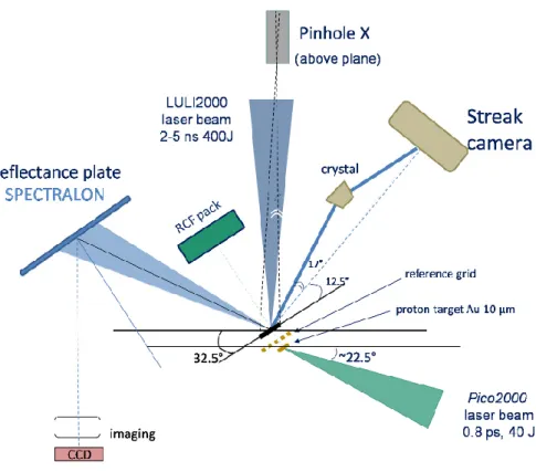
The second chapter is dedicated to the comparison between measurements performed at the JLF-Titan facility (2011) with post-processed results from FCI2 simulations, in order to assess the validity of the code. More specifically, we will discuss the possibility to per-form comparisons on deconvolved measurements with physical quantities. For example,
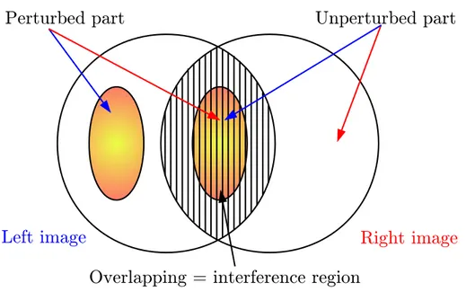
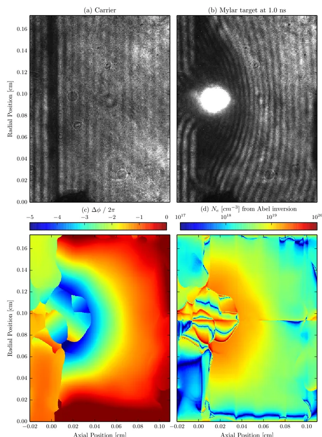
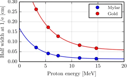
the electron density given by the simulation may be compared with the experimental one after Abel inversion of the measured phase map through interferometry, or one can cal-culate a phase map from the simulated electron density. The most important diagnostic being proton radiography [23] (the only one able to probe the magnetic field deep inside the dense part of the plasma), we will detail how the integrated magnetic field modulates the proton dose on our detector and will study the sensibility of this diagnostic to the proton energy, to the laser energy, to the laser focal spot or to the scattering of the pro-tons through the solid matter. Finally, we will show that the magnetic fields topology calculated by FCI2 using our model gives proton radiography results in agreement with the measurements, for both low and high Z targets, all along the interaction. The chap-ter will be concluded with a comparison of the different models presented in chapchap-ter 1, but this time against an experimental measurement performed on the LULI2000 facility (2008).
The third chapter is dedicated to the study of the growth and transport of the field, and its effects on the overall interaction. Using the FCI2 code, a study of the source and transport of the B-field, as well as the influence of the laser parameters, is performed for both low and high Z targets. The resulting topology of the magnetic field being understood, a study of the feedback of the field over the interaction is performed, showing that the field strongly affects the heat flux due to a strong dependence of the magnetization of the electrons through their velocity. Moreover, the effects on the ion motion (i.e. the hydrodynamics of the plasma) and the energy balance are studied. The chapter will be concluded by an extrapolation to multi-kiloJoule scales (LMJ or NIF quad irradiating a foil3) and full scale ICF experiments.
The last chapter aims at studying the reconnection of the magnetic field in the framework of our collisional laser-generated plasmas. First, a state of the art of the knowledge of the reconnection is presented, as well as the different types of codes (resistive MHD, Particle in Cell and hybrid) that can be used to investigate the physics at play, leading to the HECKLE code from LPP which will be used to design and analyse our experiments in parallel with FCI2. Indeed, a previous numerical study performed with HECKLE pointed out that the quadrupolar structure of the magnetic field in the reconnection zone (called the Hall component) may be a cause and not a consequence of the reconnection [24]. Thus, artificially inhibiting it using bended foils could reduce the reconnection rate. We will then present experiments performed at Phelix (GSI) and LULI2000, which aimed at assessing the reconnection rate in laser generated plasmas, as well as the preliminary interpretation of the experimental results using both FCI2 (simulation of a single irradiation spot) and HECKLE (simulation of the reconnection). The chapter will end with the presentation
3LMJ (Laser MegaJoule, France) and NIF (National Ignition Facility, USA) are the two currently
operating MegaJoule class laser facilities, designed to demonstrate the feasability of high gain ICF experiments. A quadruplet (or quad) is a bunch of 4 co-propagating laser beams, resulting in a 10-20 kJ laser energy in a single focal spot.
1 Modeling the heat flux in
hydro-radiative simulations
Introduction
In Inertial Confinement Fusion (ICF) and High Energy Density Plasmas (HEDP) exper-iments, the typical scales are as follow (in c.g.s.): object size of 10−1 cm, gradient lengths
in the order of 10−4cm and duration ranging from 10−10s to 10−8 s. With a characteristic
fluid velocity of 107− 108 cm/s, this results in a characteristic time around 10−13 s.
Sim-ulating this kind of experiments is thus not affordable with a Fokker-Planck code, which would describe the distribution function of the electrons and ions (or only one of them in the case of a hybrid code). Therefore, the most common method is to assume that the sys-tem is at the Local Thermodynamic Equilibrium (LTE), leading to Maxwell-Boltzmann distribution functions and hence allowing to describe the system through the different momenta of the distribution functions. This is the fluid (or hydrodynamic) framework. While the physics at play in hydro-radiative simulations is very vast, the electron thermal transport plays a major role in laser produced HEDP experiments. In the case of ICF plasmas, electron conduction strongly affects the electronic ablation front (i.e. the limit where the solid target is heated by the electron heat transport and is thus vaporized) in direct drive, as well as the x-ray emission from the high Z materials in indirect drive hohlraum. Moreover, hydrodynamics and parametric instabilities (coupling and energy transfer between electro-magnetic, ionic and electronic waves) are also sensitive to thermal conduction. Hence, an accurate modeling of electron transport in hydro-radiative codes is of great importance, as it may affect both the way laser energy is deposited in ICF experiments and the way internal energy is transported in the target.
Most commonly, the electron conduction model used in this kind of code (i.e. hy-drodynamic) is the Spitzer-Härm (S-H) linear theory, which will be described below. Yet, because the laser energy is deposited in a very small area near the critical density (Nc � 1.1 × 10²¹[cm−3] /λ2laser[µm]), the temperature profile exhibits very sharp
temper-ature gradients, leading to an overestimated heat flux due to the non-validity of the linear theory in this area. Thus, in order to correctly reproduce experimental measurements, the S-H heat flux has to be artificially limited to a maximum value [21]. This method,
while allowing to fit the results of the various observables that can be recorded indepen-dently in HEDP experiments (e.g. x-ray emission, electron temperature, hydro-motion
etc.), does not allow to match every measurements of an experiment with a single value
of the flux limiter. Furthermore, it turns out that the limitation has to be adjusted from an experiment to the other, depending on the laser parameters.
In this chapter, we will describe the different electron conduction models which can be used in our FCI2 code, starting from the Spitzer-Härm model, which depends only on the local hydrodynamics parameters. Then, we will present the various approaches aiming at improving the treatment of the heat flux : artificial limitation, linear theory in the case of a magnetized plasma, and finally, non-local models coupled with a MHD module.
1.1 FCI2: A Resistive MHD hydro-radiative code (and
more)
The physics studied in this thesis takes place in the framework of the interaction of high-power laser beams on either the wall of a high Z (such as gold) cavity in indirect drive ICF (ID-ICF), or a low Z (such as plastic) ablator of a direct drive ICF (DD-ICF) target. To be more synthetic, we have reduced the field of the first part of our study to the interaction of a single laser beam with solid foils of different atomic number. The targets, based on experimental constrains, will be presented in details in chapter 2.
1.1.1 The physics included in FCI2
The numerical simulations of the interaction of a single laser beam with a foil, that we are going to present and discuss here, were all performed with FCI2 (in French: code de
Fusion par Confinement Inertiel), an hydro-radiative code [25] developed at CEA (French
Commission for Alternate Energy and Atomic Energy), used routinely to design ICF experiments. FCI2 is a 2D axi-symmetrical hydrodynamic code (r-z cylindrical geometry), solving the equations of the classical (for laser studies) two temperature-one fluid model of the plasma [26, 27]. Indeed, because the laser deposits its energy on the electrons, this leads to a system where electrons and ions are co-moving (such as to keep the quasi-neutrality of the system), but have different temperatures. Once the laser is turned off, removing the large energy source on the electrons, the two temperatures eventually equilibrate by the action of electron-ions collisions. The FCI2 code uses the Lagrangian
formalism where Dt =
∂
∂t + (u.∇) is the Lagrangian derivative: Dtr = u
Dtρ+ ρ∇.u = 0 Mass conservation,
ρDtu + ∇P = 0 Momentum conservation,
DtEe+ Pe∇.u + ∇.Qe= Se− νei(Te− Ti) + Hrad Energy conservation (electrons),
DtEi+ Pi∇.u + ∇.Qi = Si+ νei(Te− Ti) Energy conservation (ions), (1.1)
where u is the fluid velocity, ρ is its mass density and P = Pi+Peis its total scalar pressure.
Ei,e is the internal energy of the ions (respectively electrons), Qi,e is the heat flux, Si,e is
the external energy source, Hrad represents the electron-photon energy exchange (through
a radiative equation), Ti,e is the ion (resp. electron) temperature and νei the electron-ion
collision frequency.
Because in ICF, and more generally in laser-solid interaction, the fluid is rapidly expanding or contracting, it is convenient to use the Lagrangian description, for which the reference frame moves with the flow velocity of the fluid. Indeed, in this co-moving frame, Dt
reduces to ∂
∂t, allowing to get rid of the advection terms (u.∇) of the Eulerian formalism.
Nonetheless, because in the Lagrangian description the mesh is embedded with the fluid, shear flows or vortices will lead to highly deformed meshes preventing the continuation of the simulation. In the “simple” case of a laser irradiated foil, the large variation of density at the ablation front results in highly elongated meshes and thus a small spatial resolution in the ablated part of the plasma. To solve this problem, FCI2 uses an ALE (Arbitrary Lagrangian-Eulerian) module, to transform the deformed mesh into a more regularized one.
Furthermore, to close the system (Eqs. 1.1), one needs equations of state (EOS) to calculate Pi,e(ρ, Ti,e) and Ei,e(ρ, Ti,e), which, in FCI2, are interpolated from tabulated
calculations. The difficulty comes again from the various states of the matter in this kind of experiment, from the (possibly) degenerated dense cold plasma to the hot one, having a low collisionality.
The heat transport in the system (∇.Qe in the energy equation of 1.1) can use either a
flux-limited Spitzer-Härm, Braginskii or a non-local multi-group diffusion model coupled to the self-generated magnetic field. This part will be developed afterwards in this chapter. Note that because the ionic heat flux is much smaller than the electronic one, it is treated as a linear diffusion: Qi = −κi∇Ti.
In the case of high Z materials, the transport of energy through radiation becomes dom-inant in the equation of energy. This is a long lasting subject of research and many different models have been proposed, starting, in the approximation of an optically thick
plasma, with the simplest grey diffusion , in which a mean frequency is used.
How-ever, in our case, there is a continuous transition from the optically thick solid part of the target to the optically thin low density corona. Hence, FCI2 contains a multi-group Monte-Carlo transport module [28], using tabulated opacities, corrected to account for
Non-Local Thermodynamic Equilibrium (NLTE) [29]. Note that the transport of energy
in hydro-radiative simulations is a particularly complex subject (especially in 2D), as both the electronic and radiative transports may have a long range, leading to a set of non-linear equations to solve in order to calculate the energy of the system. To be exhaustive, note that the photonic module may be coupled to an atomic physics one, in order to improve the accuracy of the opacities and ionization states.
The laser energy deposition (Se,Laser) is simulated through a 3D geometric optics
ray-tracing package, modeling absorption through inverse bremsstrahlung. Finally, in the case of full scale ICF simulations, one has to use packages for nuclear reactions, supra-thermal ions and neutron transport.
1.1.2 Hydrodynamics of a solid foil irradiated by a nanosecond laser
pulse
Before looking further in details into the issue of heat transport, we will present here the dynamics of a solid foil irradiated by a ∼ 1014W/cm2nanosecond laser pulse. The heating
from the laser launches a thermal wave in the target, heating and ionizing it, resulting in an ablation of the foil.
Fig. 1.1 illustrates in one dimension the laser which deposits its energy through inverse bremsstrahlung up to the critical density (the electron density at which the electron plasma frequency is higher than that of the laser). The thermal energy is transported toward the dense target by electron conduction until the electronic ablation front, and deeper inside the target by radiation conduction, up to the radiative ablation front [30, 31]. The resulting ablation pressure launches a shock through the target, which, upon reaching its rear face, accelerates it. Because of the fast and localized laser heating, the temperature gradient in the electron conduction zone may be very steep, resulting in electrons carrying the heat with a mean free path longer than the corresponding gradient length. This leads to the delocalization of the heat flux.
Fig. 1.2 to Fig. 1.5 present 2D FCI2 simulations with non-local electron conduction and MHD for typical HEDP parameters: 23 µm thick Mylar or 5 µm thick gold targets, ir-radiated by a 400 J, 2 ns, 300 µm FWHM focal spot and λ = 1 µm (1 ω) laser pulse,
1A grey diffusion corresponds to a diffusion mechanism for an equilibrated population (e.g. Planckian
for a population of photons or Maxwellian for a population of electrons) for which a fine description of the distribution function is not necessary.
Te
Tr
Ne
sh
o
ck
corona
electron
conduction
radiative
conduction
Nc
Laser
Space
10
21cm
-310
23-10
24cm
-3keV
100 eV
cold
Figure 1.1: 1D scheme of the irradiation of a solid foil by a ∼ 1014W/cm2 nanosecond laser pulse.
giving an intensity of ∼ 3 × 10¹⁴W/cm2. It illustrates the dynamics of the foil from
the hydrodynamics point of view. First of all, because of the lower inertia of the plastic target, thus characterized by a faster plasma motion, the electron conduction length (see Fig. 1.2 at 2.0 ns) is much longer than for the gold target. Secondly, one can see the gold target being ablated deeply by radiative energy transport (see the large region of plasma at 0.1 − 1 g/cm3). Note also the decreasing temperature in the corona, a typical result
given by non-local electron conduction models, opposed to the classical isothermal corona of the flux-limited conduction model.
Fig. 1.3 and Fig. 1.5 exhibit the repartition of energy in the system (upper/lower is the internal/kinetic energy), as it governs its evolution. It shows that in overall, the energy is lower for the gold target, as a significant fraction of the energy is lost through radiations, because of the “open” geometry of the foil (opposed to an ICF cavity). Moreover, it is important to understand that despite the high temperature of the corona, its low density implies a low internal energy. In fact, most of the system’s energy is split between internal energy at the ablation front, and kinetic energy in the accelerated foil. Most of the hydrodynamics of the foil is then determined by the dense part of the plasma. The solid iso-line represents Ma = 1 (Ma�
� � �
�[Kinetic energy]
[Internal energy]being the Mach number), i.e. the separation between compressible and incompressible fluids.
To conclude this basic introduction concerning the hydrodynamics of a laser irradiated foil, we point out that one significant peculiarity of high Z targets is the apparition of a radiative ablation front, ahead of the electronic one, resulting in a double ablation front (DAF) structure [32]: this results in an area of almost constant density and temperature,
���� ���� ���� ���� ������������������� ����� ����� ����� ����� ���� ���� ���� ���� ���� �������������������� ������� ����������� ������ ���� ���� ���� ���� ������������������� ������ ���� ���� ���� ���� ������������������� ������ ���� ���� ���� ���� ������������������� ������ ����������������� ���� ���� ���� ���� ���� ��� ��� ��������������� ��� ��� �������������������� ��� ���
Figure 1.2: Density [g/cm3] (up) and electron temperature [keV] (down) for a 23 µm thick Mylar target irradiated by a 400 J, 2 ns, 300 µm FWHM focal spot and 1 µm wavelength laser pulse. From left to right : 0.5, 1.0, 1.5 and 2.0 ns. The dotted line represents the critical density.
between the two fronts2. Because an ablation front marks a separation between the
accelerated foil (moving toward x < 0) and the ablated plasma (moving toward x > 0), it appears as a local minimum of the kinetic energy. On Fig. 1.3 one can clearly see a single ablation front, while on Fig. 1.5 there are two.
1.2 The limited Spitzer-Härm heat flux
As we saw above in (Eqs. 1.1), solving the equation of energy requires to calculate a heat flux Q, for which different assumptions may be made. First of all, because of the high mobility of electrons, we will here neglect the ions’ contribution in the heat transport. Next, for simplicity, one could assume that the transport is much faster than the system’s evolution (i.e. infinite heat flux), leading to an homogeneous temperature (isothermal assumption) or, on the opposite, that the heat transport is much slower than the system’s evolution (i.e. null heat flux, adiabatic assumption). Both assumptions strongly simplify the resolution of the electron energy’s equation, but are too restrictive for our kind of
2n.b. Because, in our case, the electron temperature is lower than 200 eV in this region, it is hardly
���� ���� ���� ���� ������������������� ����� ����� ����� ����� ���� ���� ���� ���� ���� �������������������� �������� ������� ������ ���� ���� ���� ���� ������������������� ������ ���� ���� ���� ���� ������������������� ������ ���� ���� ���� ���� ������������������� ������ ���� ���� ���� ���� ������������������������� ���� ���� ���� ���� ������������������������
Figure 1.3: Internal (up) and kinetic (down) energy density [erg/cm3] for a 23 µm thick Mylar target irradiated by a 400 J, 2 ns, 300 µm FWHM focal spot and 1 µm wavelength laser pulse, with isolines for the critical density (dashed) and Ma = 1 (solid). From left
to right : 0.5, 1.0, 1.5 and 2.0 ns.
experiments in which the heat flux ranges from one extreme to the other, depending on time and space. We thus have to calculate a finite heat flux.
1.2.1 Kinetic equation
Let us start with f(x, v, t) the electron distribution function (as said above the ion con-tribution is negligible). Its velocity moments, from which the plasma’s characteristics can be evaluated, are:
Ne=
ˆ
f d3v 0th moment : Electron density,
j = −eˆ fvd3v 1st moment : Electron current,
E = m2e ˆ fv2d3v 2nd moment : Energy, Q = me 2 ˆ
fv3d3v 3rdmoment : Heat flux, (1.2)
���� ���� ���� ���� ������������������� ����� ����� ����� ����� ���� ���� ���� ���� ���� �������������������� ������� ����������� ������ ���� ���� ���� ���� ������������������� ������ ���� ���� ���� ���� ������������������� ������ ���� ���� ���� ���� ������������������� ������ ���� ���� ���� ���� ���� ��� ��� ��������������� ��� ��� �������������������� ��� ��� ���
Figure 1.4: Density [g/cm3] (up) and electron temperature [keV] (down) for a 5 µm thick gold target irradiated by a 400 J, 2 ns, 300 µm FWHM focal spot and 1 µm wavelength laser pulse. From left to right : 0.5, 1.0, 1.5 and 2.0 ns. The dotted line represents the critical density.
f(x, v, t) is solution of the Vlasov-Fokker-Planck-Landau equation:
∂f ∂t + v · ∇xf − e me � E + v c × B � · ∇vf = Qee(f, f) + Qei(f, fi), (1.3)
where ∇xand ∇v represent respectively the gradients over the spatial and velocity
dimen-sions, −e is the electron charge, me the electron mass, (E, B) the electromagnetic field,
c the speed of light and Qee(f, f) + Qei(f, fi) are the electron-electron and electron-ion
collision operators.
1.2.2 P1 system (isotropisation)
Assuming that the distribution function is close to isotropy, we expand the distribution function in spherical harmonics [33] up to the first order [34], with v = �v� and Ω = v
v:
f(x, v, t) = f0(x, v, t)
4π + 3Ω · f1
(x, v, t)
���� ���� ���� ���� ������������������� ����� ����� ����� ����� ���� ���� ���� ���� ���� �������������������� �������� ������� ������ ���� ���� ���� ���� ������������������� ������ ���� ���� ���� ���� ������������������� ������ ���� ���� ���� ���� ������������������� ������ ��������� �������������� ���������� �������������� ���� ���� ���� ���� ������������������������� ���� ���� ���� ���� ������������������������
Figure 1.5: Internal (up) and kinetic (down) energy density [erg/cm3] for a 5 µm thick gold target irradiated by a 400 J, 2 ns, 300 µm FWHM focal spot and 1 µm wavelength laser pulse, with isolines for the critical density (dashed) and Ma = 1 (solid). From left
to right : 0.5, 1.0, 1.5 and 2.0 ns.
f0 represents the isotropic part of the distribution function (even moments : density,
energy, etc.), while f1 represents the anisotropic part (odd moments : velocity/current,
heat flux, etc.). Therefore, with d3v = v2dvdΩ, the moments of f (Eq. 1.2) become: Ne= ˆ f0v2dv, E =m2e ˆ f0v4dv, j =−eˆ f1v3dv, Q =m2e ˆ f1v5dv. (1.5)
Substituting the distribution function (Eq. 1.4), expanded up to the first order, in the VFPL equation (Eq. 1.3), directs to:
∂f0 ∂t + v∇x· f1− eE me · 1 v2 ∂ ∂v � v2f1 � = C0, (1.6) ∂f1 ∂t + v 3∇xf0− eE 3me ∂f0 ∂v − e me B c × f1 = C1. (1.7)
model) collisional operators [35, 36]: C0 =C0(f0) = νee Ne ∂ ∂v � vf0(v)E(v) + D(v)∂f0(v) ∂v � , (1.8) C1 =C1(f1) = −νei∗f1, (1.9) where νee= 4πNe e4ln Λee v3m2e and νei = 4πNie4Z2ln Λei
v3m2e are respectively the electron-electron
(ee) and electron-ion (ei) collision frequencies with Neand Nithe electron and ion density,
Z the ions’ charge state and Λee,Λei the Coulomb logarithms corresponding to e-e and
e-i collisions. Note that νei is valid only in the limit of high Z [37]. For an arbitrary Z,
νei is corrected as νei∗ = ανei =
Z+ 4.2
Z + 0.24νei. E(v) and D(v) are the isotropic Rosenbluth
coefficients [38]: E(v) = 4π ˆ v 0 f0(v �)v�2dv�, (1.10) D(v) =4π 3 v3 �ˆ v 0 f0(v �)v�4dv� + ˆ ∞ v f0(v�)v�dv� � . (1.11)
1.2.3 The Spitzer-Härm heat flux (Maxwellianisation)
Next, we assume that f0 varies slowly in space, i.e. the mean free path (mfp) of the
electrons λ(v) = v/ν(v) is smaller than a characteristic length. In other words, one can define a small parameter � = λ(v)/Lth, with Lth = Te/|∇Te| the temperature gradient
scale length. This allows us to replace f0 by the Maxwellian distribution, function of the
momenta Ne and Te (the fluid velocity is neglected, being much lower than the thermal
velocity): f0 = f0m = 4πNe � m e 2πkbTe �3 2 e−(mev2/2kbTe). (1.12)
Using (Eq. 1.7) and (Eq. 1.9) under stationary conditions (f1 is slowly varying compared
to the hydrodynamics time scale, ∂f1
∂t = 0) and null magnetic field hypothesis, leads to:
v 3∇xf0m−3meE e ∂fm 0 ∂v = −ν ∗ eif1. (1.13)
At this point, the electric field E is the only remaining unknown we need to calculate the heat flux (3rd order moment of f
1). To do so, assuming a null electric current (j = �0, 1st
in (Eq. 1.5) and keeping in mind that ν∗ ei∝ v−3: jnull= ˆ ∞ 0 � v∇xf0m− emE e ∂fm 0 ∂v � v6dv= �0 (1.14)
and therefore, after integration:
ESH = − kbTe e �∇N e Ne +5 2∇TTee � . (1.15)
Using this “Spitzer-Härm electric field” ESH in (Eq. 1.7), still without magnetic field,
gives access to fm 1 : fm 1 = −3νv∗ ei � mev2 2kbTe − 4 � f0m∇Te Te (1.16) and finally, to the Spitzer-Härm heat flux [19]:
QSH = −KSH∇ (kbTe) = −64 Y∗ ei � 2 π � kbTe me �5 2 ∇ (kbTe) , (1.17) with Y∗ ei = α � 4πe4Z2ln Λ ei m2e � .
1.2.4 Limited heat flux
As one can note, the Spitzer-Härm model leads to an implementation in the codes of a “grey diffusion”, i.e. the electrons are supposed to be at equilibrium (Maxwellian distribution function), and the transport coefficient KSH(r) depends only on the local
thermodynamics variables Te(r) and ∇Te(r). This treatment is the simplest and easiest
thermal conduction model to implement in codes. This explains why the Spitzer-Härm heat flux has been, in hydro-radiative codes, the most commonly used model for decades. Yet, it appeared very early that simulations using this model could not reproduce all the experimental measurements [39], proving that at least one of the assumptions used above is not justified. The first one which is made is that the vectorial part of the electron distribution function is a perturbation of the isotropic one : �3Ω · fm
1 � � f0m.
Let us introduce β = mev2
2kbTe
the reduced energy, Lth =
Te
∇Te
the temperature gradient length, and λth
ei =
(kbTe)2
4πe4N
eln Λei
the mean free path for an electron moving at the thermal velocity. From the expression of fm
1 (Eq. 1.16) we have: Ω · fm 1 (v) = − λ th ei 3Lth β2(β − 4) f0m(v), (1.18)
which implies:
λth ei
Lth
β2|β − 4| � 1. (1.19)
Clearly, this condition is doomed to fail with increasing β, i.e. v2. Nevertheless, one
could question the contribution of the high energy part of the distribution function to the heat flux, because of its small value. Let q(v) be the differential heat flux, defined from
Q=
ˆ
q(v)dv. From (Eq. 1.16) in (Eq. 1.5) and with ν∗
ei ∝ v−3, it comes: q(v) ∝ � mev2 2kbTe − 4 � v9fm 0 . (1.20) 0 1 2 3 4 5 6 7 v/vth −0.4 −0.2 0.0 0.2 0.4 0.6 0.8 1.0 q( v ) 3.71vth
Figure 1.6: Normalized differential heat flux q(v) from (Eq. 1.20).
Plotting q(v) from (Eq. 1.20) shows a maximum at 3.71vth(see Fig. 1.6). Using this value
of v/vth for β in (Eq. 1.19) gives us the condition:
λth ei
Lth
<2 × 10⁻³. (1.21)
While this could seem very low compared to the condition λei < Lth , one has to keep in
mind that the mean free path is function of v4, and thus λ
ei(3.71vth) � 200λthei.
Because of the very steep temperature gradients encountered in laser generated plasmas (mostly in the electron conduction area, between the ablation front and the critical density, as seen in sec. 1.1.2), this condition fails. As such, the Spitzer-Härm may result in an unphysical, over-estimated heat flux, even larger than the free-streaming heat flux:
Hence, as often with diffusive processes, the Spitzer-Härm heat flux may be limited to a fraction f of the free streaming flux, either, for example, by a sharp cut-off, or an harmonic
limitation (see Fig. 1.7):
Q= min (QSH, f.QF S) or 1 Q = 1 QSH + 1 f.QF S .
Note that there is no precise rule to determine the value of f in the simulations. It is chosen depending on the target’s material and the laser’s intensity and wavelength, such as to fit experimental data and is typically low, around 0.05 − 0.1 for a sharp cut-off [40, 41, 42]. This shows that the limited Spitzer-Härm heat flux, while convenient from a numerical point of view, cannot be predictive as the parameter f has to be adjusted a-posteriori.
10−2 10−1 100 101 102 QSH/f.QF S 10−2 10−1 100 101 Q/f .Q F S
Figure 1.7: Sharp (solid) and harmonic (dashed) cut-off.
1.3 The Braginskii heat flux
1.3.1 Linear transport
As we saw in (Eq. 1.17), the Spitzer-Härm heat flux is a linear transport model: it is proportional to ∇Te through a transport coefficient KSH. In this section we will present
the so-called Braginskii heat flux, which in fact describes the heat flux within the linear theory when the plasma is magnetized.
First, we start from the kinetic equation under the assumption of a small anisotropy (P1 system, Eq. 1.6 and 1.7). Because we are in the framework of a close to local thermodynamic equilibrium (LTE), f0 is set to the Maxwellian, and thus the 0th and 2nd
order moment (density and energy) are known. The principle of the linear theory is then to express the electric and thermal currents as linear functions of (magneto-)hydrodynamics quantities such as the electric field E, the electron temperature gradient ∇Te or the
electron density gradient ∇Ne.
The difficult part is to solve the equation for f1(Eq. 1.7) as it depends on Z, the ionization
of the plasma, and on χ ≡ ωceτei, its magnetization, where ωce =
e|B| mec
is the electron gyro-frequency and τei = 1/νei the mean collision time. To do so, the equation is solved
for given (Z, χ) couples to fill a table, which is then interpolated to give an approximated continuous expression of the coefficients, e.g. the α = Z+ 4.2
Z + 0.24, in the KSH of the
Spitzer-Härm heat flux (Eq. 1.17).
1.3.2 Braginskii’s notation
As said above, we keep the small anisotropy assumption with the scalar part of the electron distribution function set to the Maxwellian:
fBr =
fm
0
4π + 3Ω · f4π 1. (1.23) Then, the equation for f1 from the Spitzer-Härm model (Eq. 1.13), but accounting for
the magnetic field through the − e
me B c × f1 term reads: f1 = −τei � v 3∇f0m− 3meE e ∂fm 0 ∂v � − χ (b × f1) . (1.24)
Following, just like in the S-H case, one needs to calculate the electric field, which this time comes from the generalized Ohm’s law [20]:
eNeEBr = −∇Pe− eNeu × B c + j × B c + α · j Ne − Ne kbβ· ∇Te, (1.25)
while the heat flux is expressed as a function of ∇Te and j:
QBr = −
kbTe
e β· j − κ · ∇Te. (1.26)
The transport coefficients are : • α the electrical resistivity,
• β the thermo-electric conductivity tensor, • κ the thermal conductivity tensor,
• χ the plasma’s magnetization (also called Hall parameter), function of the thermal velocity vth in the linear theory.
Using Braginskii vectorial notation [20], the components of these tensors are given for any vector s and b = B
�B� as:
ψ· s = ψ�b(b · s) + ψ⊥b× (s × b) + ψ∧b × s, (1.27) i.e. � is the direction of b, ⊥ is the direction perpendicular to b but collinear to s, and
∧ is the direction perpendicular to both vectors. For example, in an axi-symmetrical geometry, with b being on the (Oθ) axis and ∇Te in the (Oz, Or) plane, Q⊥ denotes
the heat flux in the direction of ∇Te, while Q∧ denotes the heat flux in the direction
perpendicular to ∇Te (see Fig. 1.8).
B
ψ
ψ⊥ ψ||
ψ^
Figure 1.8: Braginskii’s vectorial notations.
Solving equations (Eq. 1.24 – 1.26) requires to calculate the set of coefficients�α, β, κ�for
fixed (Z, χ) couples. In order to do so, different methods have been proposed. Some are analytical, involving an expansion of f1 in polynomials with a truncation after a number
of terms [43, 44]. Others [45] computed the solution through finite differences. Once a table of coefficients is filled for discrete Z and χ, one can fit the results to estimate a continuous ci(Z, χ) (ci representing one of any coefficient listed above). Note that the
resulting coefficients can only be used in a validity domain restricted by the hypothesis made to solve f1. One could cite for example the Hubbard thermal conductivity [46] valid
for fully degenerated plasmas (Te < TF ≡ �
2 3me � 3π2N e �2/3
) in the limit Z → ∞, or Lee and More who calculated a set of coefficients for the liquid and solid phases within an arbitrary magnetic field [47].
1.3.3 The Righi-Leduc effect
In this subsection we will introduce the so-called Righi-Leduc (R-L) effect. As we saw, when the plasma is magnetized, the thermal conductivity coefficient becomes a tensor
KSH → κ, i.e. the conduction is anisotropic. This tensor can be expressed as a function
of the Spitzer-Härm conductivity: κ = KSHX, and thus, the Braginskii heat flux (Eq.
1.26) can be rewritten as a function of the Spitzer-Härm one:
QBr = − kbTe e β· j + X · QSH = � −kbTe e β⊥j + X⊥QSH � + b × � −kbTe e β∧j + X∧QSH � . (1.28)
Fig. 1.9 is plotting, in the limit Z → ∞ (Lorentz model) and under a null electrical current hypothesis, both the components and the module of QBr normalized to �QSH� as
a function of the Hall parameter (magnetization, see page 26) χ(Ne, Te, B). It illustrates
the behavior of the heat flux in the presence of a magnetic field : • In the limit χ → 0, QBr → QSH.
• For 0.01 < χ < 0.1 (weakly magnetized plasma), the module of the heat flux stays close to the non-magnetized case, but its direction is rotated toward b × ∇Te, up
to ∼ 45°.
• For χ > 0.1 (magnetized plasma), the heat flux is even more rotated toward b×∇Te,
but it starts to be inhibited due to ωce � νei.
• In the limit χ → ∞, �QBr� → 0, the thermal transport is completely inhibited as
the electrons are trapped by the magnetic field (ωce > νei): even if the collisions are
still at play, the electrons don’t have enough mobility to transport the heat. Righi-Leduc effect
In the regime of a weakly magnetized plasma, the heat flux is rotated in the b × ∇Te direction, without a significant loss in strength.
1.4 The magneto-hydrodynamic framework
In the last section we saw that the behavior of the electron conduction in the plasma is strongly modified in the presence of a magnetic field. Yet, it only appeared in the equations in the form of a magnetization χ and a direction b. In this section we will look in more details at the magnetic field induction ∂B/∂t, i.e. which are the physical mechanisms that are at the source of the field, its transport and its relaxation.
10−3 10−2 10−1 100 101 χ 0.0 0.2 0.4 0.6 0.8 1.0 X X∧ X⊥ � X2 ⊥+ X∧2
Figure 1.9: X⊥, X∧ and �X⊥2 + X∧2 as a function of the magnetization χ, for Z → ∞ and j = −→0 .
Taking into account the electro-magnetic field in the fluid equations leads to the
Magneto-Hydrodynamic (MHD) framework, i.e. a single fluid (and two temperatures in our case)
model in which the thermodynamic and electro-magnetic quantities (ρ, P, u, j, B, E) are determined via the simultaneous resolution of the equations of mass conservation, momen-tum conservation, generalized Ohm’s law, Ampere’s law and Faraday’s law, completed by a set of equations of state.
1.4.1 Momentum equation, the Laplace (Lorentz) force
Let us start with the momentum equations for the ions and electrons which are affected by the pressure of the other total ion population Pi (respectively electron population Pe),
the Lorentz force and Rie the electron-ion collision term:
NimiDtui = −∇Pi+ eZNi � E + ui c × B � − Rie, (1.29) NemeDtue = −∇Pe− eNe � E + ue c × B � + Rie, (1.30) with Dt = ∂
∂t + (u.∇) the Lagrangian derivative. Adding (Eq. 1.29) to (Eq. 1.30) when me/mi → 0 (hence u = ui) and eNe(ui− ue) = j, gives the fluid’s momentum equation:
ρDtu = −∇P +
1
where on the right hand side of the equation, the “−4π (j.∇) j/ωpe” term has been
ne-glected3 (ω2
pe = 4πNee2/me is the plasma frequency).
The fluid’s motion is then governed not only by the fluid pressure but also by the Laplace (Lorentz) force. Note that using Ampère’s law, the Laplace force may be written :
FLaplace =
1
cj × B
= 4π1 (∇ × B) × B
= 4π1 (B · ∇) × B − ∇�B�8π2.
The second term corresponds to the magnetic pressure Pmag = �B�
2
8π , while the first cor-responds to a magnetic tension. Because of the cylindrical geometry (�B� = B.eθ),
the magnetic tension may be rewritten Tmag = −
2Pmag
r er, with r = r.er [48, 49]. The
momentum equation then reads:
ρDtu = −∇P − ∇Pmag+ Tmag. (1.32)
1.4.2 Energy equation
The presence of magnetic fields in the system also implies a modification in the en-ergy equation(s). Indeed, some enen-ergy is taken from the hydrodynamics to build up the magnetic field (see the magnetic pressure term in the momentum equation), and on the opposite side, the magnetic field releases some energy back to the hydrodynamics. The evolution of the magnetic energy then reads:
DtPmag = Dt B2 8π = 8π1 � ∂B2 ∂t + u.∇B 2+ B2∇.u�= 1 8π � ∂B2 ∂t + ∇. � B2u� � .
Using Ohm’s law (Eq. 1.25), one may write the equations for the internal, kinetic and magnetic energies. (For visibility, only the exchange terms are shown, not the transport
3If L is a characteristic length of the system then, with Ampere’s law j = c
4π ∇ ×B, the 1
c j × B term
has the dimension �B2/L�, while the −4π (j.∇)j/ω2pe term has the dimension �c2B2/L3ω2pe�. The
ratio of the two gives the dimension�L2ωpe2 /c2�, yet L � c/ωpe= δnc, where δncis the non-collisional skin depth.