HAL Id: hal-01828789
https://hal-imt-atlantique.archives-ouvertes.fr/hal-01828789
Submitted on 3 Jul 2018
HAL is a multi-disciplinary open access
archive for the deposit and dissemination of
sci-entific research documents, whether they are
pub-lished or not. The documents may come from
teaching and research institutions in France or
abroad, or from public or private research centers.
L’archive ouverte pluridisciplinaire HAL, est
destinée au dépôt et à la diffusion de documents
scientifiques de niveau recherche, publiés ou non,
émanant des établissements d’enseignement et de
recherche français ou étrangers, des laboratoires
publics ou privés.
Volume diffraction gratings for optical
telecommunications applications: design study for a
spectral equalizer
T Loukina, S Massenot, R Chevallier, Kevin Heggarty, N Shigapova, A
Skochilov
To cite this version:
T Loukina, S Massenot, R Chevallier, Kevin Heggarty, N Shigapova, et al.. Volume diffraction gratings
for optical telecommunications applications: design study for a spectral equalizer. Optical Engineering,
SPIE, 2004, �10.1117/1.1803848]�. �hal-01828789�
C O M M U N I C A T I O N S
Volume diffraction gratings for
optical telecommunications
applications: design study
for a spectral equalizer
T. Loukina
GET/ENST Bretagne Technopole Brest Iroise CS 83818
29238 Brest Cedex 3, France and
State Institute of Applied Optics (GIPO) 420075, Kazan, Russia E-mail: [email protected] S. Massenot R. Chevallier K. Heggarty GET/ENST Bretagne Technopole Brest Iroise CS 83818
29238 Brest Cedex 3, France
N. M. Shigapova A. F. Skochilov
State Institute of Applied Optics (GIPO) 420075, Kazan., Russia
[DOI: 10.1117/1.1803848]
Subject terms: spectral equalization; surface relief gratings; volume-phase holographic gratings; dichromated gelatin; packag-ing; optical telecommunications.
Paper 431108 received Dec. 1, 2003; revised manuscript received Jun. 30, 2004; accepted for publication Jul. 27, 2004. © 2004 Society of Photo-Optical Instrumentation Engineers.
The main characteristics required for a diffraction grat-ing used for共de兲multiplexing functions in spectral equaliz-ing systems are investigated, both theoretically and experi-mentally. We show that volume-phase holographic 共VPH兲 gratings can be used as dispersive elements instead of clas-sic reflection surface-relief gratings presently employed in most optical telecommunications devices. A design method for this type of diffraction grating and experimental results are presented, confirming that VPH gratings are well suited to such applications.
1 Introduction
Optical telecommunications networks have improved con-siderably over the last ten years, in order to constantly sat-isfy the growth of bit rate, mainly due to the internet traffic increase and the multiplication of multimedia services.
The main technological advances that have permitted this evolution are the introduction of the optical amplifier at the end of the 1980s and the use of wavelength division multiplexing 共WDM兲 in the middle of the 1990s. These advances have led to a need for specific components and subsystems, particularly spectrally selective components to assure filtering functions or those with a high dispersive power for wavelength multiplexing functions.
In WDM systems, several wavelengths共often referred to as channels, each corresponding to an optical carrier兲 propagate simultaneously. These optical carriers are defined by the so-called ITU grid. The spectral bandwidth currently used in optical links is the C band共C for conventional兲 and is defined for channels going from ⫽1530.33 nm to
⫽1569.59 nm with a spacing of around 0.8 nm 共which
corresponds to a frequency spacing of 100 GHz; the ITU grid is defined in frequency兲.
When designing a diffraction grating for use in a tele-communications system, the technical constraints are strongly linked to the application domain. Diffraction grat-ings can be used for example as filters, demultiplexers, or dispersive elements in spectral equalizers. The constraints will not be the same for these three applications, in particu-lar spectral selectivity and dispersive power will not be optimized in the same way.
The aim of this paper is to present a design method for a diffraction grating destined for optical telecommunications. A universally applicable component does not exist, so the method presented here will be tailored for a specific appli-cation. We will illustrate this with a concrete example: the design of a dispersive element used in a spectral equalizer. First we review the main characteristics of diffraction gratings共either surface-relief or volume-phase holographic gratings兲. Then we present the telecommunications applica-tion and the constraints the diffracapplica-tion grating has to satisfy in order to guarantee optimal performance of the final com-ponent.
We will show the link between the gratings’ properties and the constraints imposed by the desired application in order to extract the engineering rules and trade-offs in-volved in the design of such gratings.
Finally, experimental results will be presented where we show that the present approach is validated since it fullfils all specifications required by this specific telecommunica-tions application.
2 General Characteristics Required for a Diffraction Grating Used in
Telecommunications Systems
2.1 Main Diffraction Grating Characteristics
We recall here the main physical characteristics of diffrac-tion gratings, which are pertinent for our applicadiffrac-tion.
Diffraction efficiency. The diffraction efficiency共DE兲 in a given diffracted order m is defined by the ratio between
the diffracted intensity in this order and the incident beam intensity: DEm⫽Idi f m/Iinc. It is wavelength, angle, and
polarization dependent.
Polarization sensitivity. For gratings with high spatial frequencies共grating period ⌳ is the same order as the op-erating wavelength兲, the diffraction efficiency can be dif-ferent for two orthogonal polarizations共TE when the elec-tric field is parallel to the grooves of the grating and TM when it is perpendicular to the grooves兲. The grating is defined to be polarization insensitive if the difference be-tween corresponding diffraction efficiencies is less than a few percent.
Spectral uniformity. We mentioned above that the dif-fraction efficiency is wavelength dependent. The need for a spectral uniformity of diffraction efficiency depends strongly on the application. For example, for spectral equal-izing it is desirable to have a spectral response as flat as possible共this is not the case if we are interested in filtering functions兲.
Angular dispersion. The classical grating equation is given by:
m⫽⌳共sin␣⫹sinm兲 共1兲
where␣ is the angle of incidence, m is the angle of the
m’th diffracted order 共the angles are measured from the
grating normal兲, and ⌳ is the period of the grating 共⌳⫽1/, where is the spatial frequency given in mm⫺1兲.
The angular dispersion of the grating is the angular sepa-ration between different wavelengths in the same diffracted order:
D⫽m
⫽ m
⌳ cosm 共2兲
The angular dispersion for a given spatial frequency can be improved by increasing the anglem共grazing incidence兲 or
by using asymmetric fringes for a volume-phase holo-graphic grating. For an optical system, we are more inter-ested in the spatial dispersion, which is the product of the angular dispersion D 关see Eq. 共2兲兴 and the focal length of the system f.
2.2 Telecommunications Viewpoint
2.2.1 Focused application: a spectral equalizer
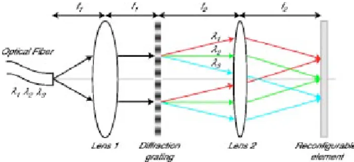
In optical telecommunications, a spectral equalizer is a component able to modify the spectrum of a signal by in-troducing selective losses using a reconfigurable element over a wavelength range. This equalizer is said to be dy-namic if it is reconfigurable. The main functions that this component can provide to optical networks are gain equal-ization共the wavelength dependence of an optical amplifier gain has to be corrected in order to have the same signal quality over the C band兲 and wavelength routing 共mainly destined to the next generation of optical networks兲. A basic schematic of a spectral equalizer is shown in Fig. 1.
Concerning the diffraction grating, the retained architec-ture for the spectral equalizer imposes some requirements
on this diffraction grating. In this configuration, the grating has to work at a fixed incidence, in a non-Littrow mount and has to work in a double-pass scheme共hence the need for a high diffraction efficiency兲.
2.2.2 Critical parameters for diffraction gratings used as dispersive elements in a
telecommunications system
When a new component is introduced in an optical link, it generally degrades the signal quality. This leads to system penalties, principally the following.
Insertion loss (IL). This corresponds to the optical power loss generated by the component. It is defined as the ratio between the output and input powers. In telecommunica-tions, the typical unit is the decibel 共dB兲, so the insertion loss in dB corresponds to the difference of the output and input powers in dBm共logarithmic optical power relative to 1 mW兲.
IL共dB)⫽Pout共dBm兲⫺Pinc共dBm兲 共3兲
Polarization dependent loss (PDL). Another character-istic is the loss due to the components’ polarization sensi-tivity. Since, the polarization state of a beam at the output of a fiber is generally unknown, the response of a compo-nent used in telecommunications has to be the same 共with as little variation possible兲 whatever the polarization state. The quantity that measures this polarization sensitivity is called polarization dependent loss 共PDL兲. It is defined as the ratio between the maximum and minimum powers at the output for all possible input polarization states. In tele-communications, it is defined in dB by the difference of these two optical powers 共maximum and minimum兲 in dBm. For a diffraction grating, it is given by the logarithm of the ratio between diffraction efficiencies DE for the TE and TM polarization states:
PDL⫽10
冏
log冉
DETEDET M
冊
冏
共4兲Wavelength dependent loss (WDL). This penalty is linked to the wavelength dependence of the insertion loss
共IL兲, and it defines the uniformity of IL on the considered
spectral bandwidth. It is defined as the difference in dB between the maximum and minimum values of loss due to the variation of the wavelength and given by:
Fig. 1 Example of a spectral equalizer architecture. COMMUNICATIONS
2659 Optical Engineering, Vol. 43 No. 11, November 2004
WDL共dB)⫽ILmax共dBm兲⫺ILmin共dBm兲 共5兲 where ILmaxand ILmin are the maximum and minimum in-sertion loss of the grating over the whole spectral band-width.
Another important parameter is the system resolution. It is not considered as a penalty but it is linked directly to the focused application and the design of the component de-pends on this parameter. For a system using a dispersive element the resolution is linked to the angular dispersion. For a classical multiplexing function, all channels have to be separated by the diameter of an optical fiber 共125
m兲.1,2 Also, to reduce overall system size, the grating should be highly dispersive. For spectral equalizing sys-tems, the constraints are not the same, in particular the required resolution is lower than for multiplexers/ demultiplexers. The behavior of the grating will be differ-ent and specific engineering rules in the design have to be used. Hence, the value of spatial dispersion defines a couple共focal length f/spatial frequency兲 for which we can satisfy the specifications of the system.
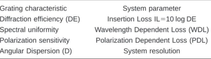
2.3 Equivalences between Grating Characteristics and Telecommunications Parameters
The equivalences between grating characteristics and tele-communications systems parameters are defined in Table 1. For a grating used as dispersive element in a spectral equalizer, typical specifications are:
IL⬍1.0 dB 共diffraction efficiency more than 80%兲 PDL⬍0.1 dB 共diffraction efficiency variations with po-larization state less than 2%兲
WDL⬍0.1 dB 共diffraction efficiency variations with wavelength less than 2%兲
The system resolution depends strongly on the applica-tion and the packaging constraints共nearly 0.02 deg/nm in our case兲.
2.4 Industrial Constraints
This section addresses mass-production and packaging con-straints. Like all optical components used in telecommuni-cations systems, diffraction gratings must be inexpensive in mass production. A good reproducibility and stability of technological process are required to maintain systems specifications. The diffraction grating should also be easy to manipulate and present a highly protected surface.
Telecommunications equipment must withstand rigorous environmental constraints. They can be used either in sub-sea links or in terrestrial networks in different climates. Diffraction gratings used in such equipment contribute to the reliability of the component. These constraints are
specified by standardization organisms. For example, Tel-cordia’s assessments indicate that the IL and PDL varia-tions must be less than 0.1 dB when the grating is submit-ted to severe thermal constraints. Devices must also pass the high-temperature storage test 共⫹85°C兲, low-temperature storage test 共⫺40°C兲, and thermal operating cycles from ⫺5°C to ⫹70°C. The number of hours and cycles is specified by standards共full details are given in the Telcordia specification GR-1221-CORE concerning passive optical components兲.
Although the angular selectivity is a physical character-istic, we treat it in this section because it is directly related to the mechanical precision of the system. If we have a flat diffraction efficiency versus the incidence angle over the desired spectral bandwidth, angular tolerances of mechani-cal alignment can be relaxed. This can lead to cost reduc-tions for the manufacturer.
3 Choice of Grating
3.1 Which Types of Grating Can Be Used?
Among the diverse family of diffraction gratings, we have to choose those which satisfy the required physical param-eters 共high diffraction efficiency, high spectral uniformity over the C band, low PDL, low angular selectivity, etc兲.
If we retain the diffraction efficiency value as a criteria, we have to orient our choice to phase gratings, which are more efficient than amplitude gratings. Then, we have to choose between thick transmission volume-phase gratings and reflection surface relief gratings. Thick reflection volume-phase gratings are more suitable for filtering func-tions.
3.2 Surface Relief Grating
Reflective surface relief gratings in the Littrow configura-tion are probably the most used diffractive elements in spectrometry and telecommunications. They have already proved their efficiency for standard multiplexing operations.2 With a suitable blaze angle, a high reflective diffraction efficiency in a fixed order can be obtained.
Another parameter to take into account is the presence of Wood anomalies for TE polarization, which produce un-desirable brutal changes in the diffraction efficiency re-sponse of the grating. These are often present for this type of grating. That is why it is impossible to provide polariza-tion independence for arbitrary spatial frequencies.
One solution is to use this grating with optimal polariza-tion. For such a solution, we have to split the input signal into its two principal states and use a polarization diversity system. The two beams共having the same polarization state兲 are then recombined after passing through the grating. A disadvantage of this solution is that it can introduce an optical path difference between the two principal states of polarization, which leads to a pulse spreading. This phe-nomena is called polarization mode dispersion in telecommunications3and leads to a degradation of the sig-nal quality. Another major disadvantage is the increase in the number of components and hence the cost.
An alternative solution is to manufacture gratings with nonstandard profiles in order to obtain the same efficiency for both polarizations. Among these solutions, we can cite:
Table 1 Main physical characteristics and requirements of a diffrac-tion grating and the corresponding telecommunicadiffrac-tions system pa-rameters.
Grating characteristic System parameter Diffraction efficiency (DE) Insertion Loss IL⫽10 log DE Spectral uniformity Wavelength Dependent Loss (WDL) Polarization sensitivity Polarization Dependent Loss (PDL) Angular Dispersion (D) System resolution
the corners of the grating profile are rounded4
the superposition of different etch depths5 or grating periods6,7
a wise choice of the incident medium8 provides good results for some restricted applications.
A major disadvantage lies in the fact that such profiles are difficult to manufacture. In addition, the optimization for polarization independence is available only for certain values of grating periods or wavelengths, which restricts the field of applications.
A major advantage of a classical surface relief grating is the ability to produce many replicas with a single master grating, greatly reducing the costs. On the other hand, sur-face relief gratings are considered to be fragile. Perfor-mance degradations occur if the surface is contaminated during assembly or during operation.
3.3 Volume-Phase Holographic Gratings
3.3.1 Introduction
Volume-phase holographic gratings are starting to find industrial applications, for example in astronomy and spectroscopy9–11 and wavelength division multi-plexing.12–14
It is theoretically possible to obtain a 100% diffraction efficiency in the first order for a thick volume-phase grating working under Bragg conditions. A hologram can be con-sidered as ‘‘thick’’ if the Klein factor Q, which is deter-mined by
Q⫽ 2T n
¯⌳2cos, 共6兲
is higher than 10. Here T is the thickness of the grating, n¯
is the average refractive index,is the incident angle inside the grating, and⌳ is the grating period.
In this case, the classical theory of Kogelnik15gives ex-cellent results. Very good agreement was obtained by com-paring this theory with results given by the rigorous coupled-wave theory of Moharam and Gaylord16 共a stable implementation was used17 in order to avoid numerical contaminations due to the high thickness of the volume phase grating兲.
Under Bragg conditions, the maximum of diffraction ef-ficiency for transmission gratings is defined by:
DE⫽sin2v 共7兲
where v depends on the polarization of the incident beam:
再
vTE⫽⌬nT cos
vT M⫽vTEcos共2兲
. 共8兲
Hereis the Bragg angle inside the grating.
In addition, this theory enables us to express the spectral bandwidth for transmission VPH gratings by15:
⌬⯝⌳
T cot. 共9兲
The polarization sensitivity is proportional to the cos(2B)关see Eq. 共8兲兴 term, which means that if we have a
maximum for the TE polarization, the maximum for the TM polarization will be shifted to shorter wavelengths
共both polarizations can reach 100% diffraction efficiency兲.
In the following, we will see that the polarization sensitiv-ity can be reduced by adjusting parameters such as grating thickness T and refractive index modulation⌬n.
The principal benefits of VPH gratings in comparison with surface relief共SR兲 gratings are the following:
theoretical diffraction efficiency up to 100%
VPH gratings lack many of the grating anomalies appar-ent in SR gratings
VPH gratings can be produced with arbitrary spatial fre-quencies
low polarization sensitivities are possible with low and high dispersion transmission VPH gratings
VPH gratings can be tuned to shift the diffraction effi-ciency peak to a desired wavelength.
Both gratings 共VPH and SR兲 can have their surfaces protected from impurities but VPH gratings are encapsu-lated between two glass substrates, hence their optical sur-faces are naturally protected. Antireflection coatings can be applied to the outer surfaces to minimize Fresnel reflections and maximize throughput.
VPH gratings have disadvantages concerning the repro-ducibility of the process; all the recording parameters must be controlled precisely 共humidity if we use dichromated gelatin, for example兲. In addition, there are few manufac-turers of suitable photosensisitive materials.
We can see that both surface relief and volume-phase holographic gratings are suitable for multiplexing func-tions. The choice between these two gratings is not clear: both have advantages and disadvantages. Generally, surface relief gratings are used for such applications, and they have been widely studied.1,2We will show in the following that a volume-phase grating can also satisfy telecommunications requirements.
3.3.2 Design rules
The design of a VPH grating destined for telecommunica-tions has to satisfy the following trade-offs in order to sat-isfy the physical and industrial constraints:
Diffraction efficiency/WDL. The spectral uniformity over a working spectral band for a given spatial frequency and for transmission VPH gratings can be improved to the detriment of the maximum diffraction efficiency 共see, for example, Ref. 14兲.
WDL/hologram thickness. Equation共9兲 shows that the spectral bandwidth共and consequently the spectral flatness兲 and the hologram thickness are inversely proportional.
Hologram thickness/refractive index modulation. For fixed wavelength and spatial frequency, these two param-eters determine the maximum achievable diffraction effi-ciency关DE⫽100% if vTE⫽/2 into Eq.共8兲兴.
Angular dispersion/polarization sensitivity
or PDL. Both parameters depend on Bragg angle. The grating’s PDL is minimal if cos共2兲⬃1.
COMMUNICATIONS
2661 Optical Engineering, Vol. 43 No. 11, November 2004
Angular selectivity/mechanical precision. The holo-graphic material must be chosen to satisfy the volume con-dition and to provide a sufficiently high refractive index modulation. The designer must allow for diverse changes in the material caused by the process 共recording and development兲18 共this aspect is described in more detail in Sec. 4.2兲.
4 Volume Phase Holographic Grating Used for Spectral Equalization Systems
As explained above, we selected the transmission volume-phase holographic grating for our application, and we now present simulation results that show the behavior of such a grating. We will be able to check that such gratings satisfy the requirements described in Sec. 2.
For a spectral equalizer application, taking into account the architecture, the tunability required, and that the typical WDM channel spacing is 0.8 nm, the required spatial dis-persion共product f D) is of the order of 0.02 mm/nm.
4.1 Spatial Frequency Design
For different focal lengths f of the system and for a given spatial dispersion, we will derive first the appropriate grat-ing spatial frequency. Then usgrat-ing Kogelnik’s theory as a modeling tool, we will determine which of these gratings is the most likely to give the best physical parameters.
The determination of the spatial frequencyis achieved by solving the system:
再
D f⫽ fcos
sin⫽
冉
0⫾2⌬ 2冊
共10兲
where 0⫽1550 nm is the central wavelength for the C
band and⌬⫽20 nm is the half spectral bandwidth. The focal length of the system depends strongly on the architecture and packaging constraints. We will give simu-lation results with focal lengths suitable for our spectral equalization application. As an example, we take values of 100 mm, 75 mm, 50 mm, and 25 mm. The corresponding spatial frequencies are: 1⫽230 mm⫺1, 2⫽300 mm⫺1, 3⫽440 mm⫺1, and4⫽750 mm⫺1.
4.2 Symmetric or Asymmetric Grating
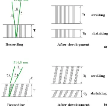
The easiest way to use a grating and a component in gen-eral is at normal incidence, which makes the packaging easier. As shown in Fig. 2共a兲, a grating with tilted 共asym-metric兲 fringes is able to work at normal incidence unlike an untilted共symmetric兲 transmission grating Fig. 2共b兲.
However, using a tilted holographic grating presents some disadvantages from a technical viewpoint. Volume-phase gratings are recorded optically in an appropriate ho-lographic material such as dichromated gelatin 共DCG兲 or photopolymers. Both of these materials are capable of pro-viding sufficient refractive index modulation to give high diffraction efficiencies. But these materials have defects due to the recording and development processes. DCG and photopolymers undergo respectively a swelling and a shrinkage, which change the angle of the fringes共and
con-Fig. 2 Grating configuration: (a) asymmetric and (b) symmetric.
Fig. 3 Illustration of swelling and shrinkage effects into holographic materials for (a) symmetric and (b) asymmetric gratings.
Fig. 4 Grism configuration: (a) inline or (b) with angular deviation.
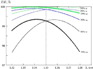
Fig. 5 Diffraction efficiency versus wavelength for four different gratings. The grating thickness for each grating spatial frequency is different to satisfy the volume grating conditionQ⫽10: 2.5m for 750 mm⫺1; 7.7m for 440 mm⫺1; 21.7m for 300 mm⫺1; and 28.0
sequently the period兲 of the grating if it is asymmetric 共see Fig. 3兲. As a result, the diffraction efficiency maximum will not be centered on the spectral bandwidth for normal inci-dence. These effects are not easy to control in an industri-alization situation, hence our choice of a symmetric grating, whose period is not affected by the development process and for which Bragg angle is constant.
It is possible to work inline with an untilted transmission grating by using a grism configuration19,20共see Fig. 4兲. The angles of the prisms are calculated in order to be at Bragg incidence for the center wavelength of the spectral band-width. Prism dispersion 共traditionally made of standard glasses like BK-7兲 can be neglected inside the relatively narrow operating spectral bandwidth共only 40 nm兲.
4.3 Simulation Results
To maximize the diffraction efficiency of a VPH grating, we have to optimize two parameters, which are the thick-ness T of the holographic material and the refractive index modulation⌬n 关according to Eq. 共8兲兴. These values have to be realistic compared to values obtainable with holographic materials. On the other hand, for a given spatial frequency, low values of grating thickness关according to Eq. 共10兲兴 al-low optimization of spectral flatness and WDL.
In Fig. 5, we present spectral curves for four different gratings; the thickness for each grating has been calculated in order to satisfy the volume condition (Q⫽10): 2.5 m for 750 mm⫺1; 7.7 m for 440 mm⫺1; 21.7 m for 300 mm⫺1; and 28.0m for 230 mm⫺1. We can see that for the 750 mm⫺1 grating the difference in diffraction efficiency between two polarization states and corresponding PDL is too high共about 20% or 1 dB at 1.55m兲.
In addition, its spectral uniformity over the band 1.5–1.6
m is insufficient. This grating was therefore rejected. For the three remaining gratings, Fig. 6 shows the varia-tion of diffracvaria-tion efficiency for the TE polarizavaria-tion with index modulation under Bragg conditions for fixed gratings thicknesses.
We know that a higher spatial frequency and a low thickness give a good trade-off between diffraction effi-ciency and spectral bandwidth, but the required value of
⌬n has to be realistic. For example, in the case where the
thickness T just satisfies the Q⬇10 condition, the refractive index modulation required for spatial frequency 440 mm⫺1 is equal to 0.08 关Fig. 6共a兲兴. This value is very high for traditional holographic phase materials. It can be reached only with dichromated gelatin with extremely well con-trolled process parameters, which complicates industrial
Fig. 6 Diffraction efficiency as a function of index modulation: (a) grating thickness varies with spatial frequency: 10 m for 440 mm⫺1, 25m for 300 mm⫺1, and 30m for 230 mm⫺1; (b) grating
thickness is constant (25m).
Fig. 7 Improved spectral diffraction efficiency for three VPH grat-ings with the same grating thickness (25m) and a refractive index modulation of nearly 0.03 for each grating.
Fig. 8 Insertion loss for the 230 mm⫺1grating at the Bragg angle for
both polarization states.
COMMUNICATIONS
2663 Optical Engineering, Vol. 43 No. 11, November 2004
production. According to the second set of curves 关Fig. 6共b兲兴, a thickness of 25 m requires modulations of the order of 0.03, which are easier to reach.
Figures 5 and 6 show that for both polarizations, the diffraction efficiency 共DE兲 can reach 100% but the TM polarization’s maximum is shifted to short wavelengths compared to TE polarization and the refractive index modulation needed for DE optimization is not the same. Consequently, there is a simple technique to improve sig-nificantly the spectral uniformity and polarization depen-dent loss for transmission VPH gratings, if for the central wavelength the refractive index modulation is chosen to have the same values of DE for both polarization states.
Figure 7 illustrates this possibility. It shows the spectral response of these three gratings over the C band with a constant thickness of 25m, which is a standard thickness for DCG layers共PFG-04 from ‘‘Slavich’’兲 used in grating production. The refractive index modulation for each grat-ing was calculated to give the same diffraction efficiency for both polarizations at the central wavelength共1.55m兲. We can see clearly that the three parameters 共IL, PDL, and WDL兲 are best for⫽300 mm⫺1and⫽230 mm⫺1.
5 Experimental Results with Volume-Phase Holographic Gratings
Despite the fact that the development process is complex, dichromated gelatin共DCG兲 is the most commonly used ma-terial for industrial applications of volume-phase gratings. We present here experimental results obtained for three volume-phase holographic gratings recorded in standard dichromated gelatin layers with a thickness T of 25 m
共with spatial frequencies of 230, 300, and 500 mm⫺1兲.
Despite the simulation results, a spatial frequency of 500 mm⫺1was chosen to illustrate in practice the importance of the trade-offs given in Sec. 3.3.2. This spatial frequency is
at the limit of the required characteristics if we refer to the simulation results. We will see in the following that such a choice would have degraded considerably the performance of the system.
All gratings were studied over the C band for both TE and TM polarizations. We give spectral curves in the tele-communications context 共insertion loss instead of diffrac-tion efficiency and PDL for polarizadiffrac-tion sensitivity兲. The 230 mm⫺1 共Fig. 8兲 and 300 mm⫺1共Fig. 9兲 gratings show high diffraction efficiency 共close to 90%兲, high spectral flatness, and low PDL. However, for the 500 mm⫺1grating
共Fig. 10兲 all required characteristics are slightly increased.
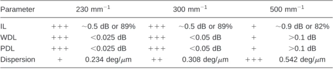
For example, average diffraction efficiency for this grating varies between 79.5% and 82%, which gives us insertion loss of about 1 dB. Table 2 shows the main characteristics for each grating.
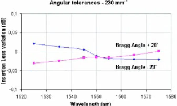
These gratings were tested not only for Bragg incidence but also for small mismatches of the Bragg condition共Figs. 11, 12, and 13兲 to estimate angular tolerances. We can see that angular tolerances for the 500 mm⫺1grating are con-siderably reduced.
As a conclusion, the 300 mm⫺1grating seems to give a better trade-off over the parameters IL, WDL, and PDL as well as dispersion. Such a grating would be entirely suit-able for a DSE application. This grating was tested under thermal Telcordia tests. Figure 14 shows the variations in average insertion loss for different temperatures.
6 Conclusion
Design of a diffraction grating destined for dynamic spec-tral equalization functions in telecommunication has been presented. The configuration of the system defines the type of grating to be used. In addition, the grating has to satisfy telecommunications criteria such as low insertion loss共IL兲, wavelength dependent loss共WDL兲, polarization dependent
Fig. 9 Insertion loss for the 300 mm⫺1grating at the Bragg angle for both polarization states.
Fig. 10 Insertion loss for the 500 mm⫺1grating at the Bragg angle
for both polarization states.
Table 2 Grating characteristics from a telecommunications viewpoint and performance comparisons.
Parameter 230 mm⫺1 300 mm⫺1 500 mm⫺1
IL ⫹⫹⫹ ⬃0.5 dB or 89% ⫹⫹⫹ ⬃0.5 dB or 89% ⫹ ⬃0.9 dB or 82%
WDL ⫹⫹⫹ ⬍0.025 dB ⫹⫹⫹ ⬍0.05 dB ⫹ ⬎0.1 dB
PDL ⫹⫹⫹ ⬍0.025 dB ⫹⫹⫹ ⬍0.05 dB ⫹ ⬎0.1 dB
loss 共PDL兲, and dispersion constraints. Other parameters such as the angular selectivity allow the designer to flag mechanical constraints.
Generally, surface relief gratings are chosen for such applications. We have shown in this paper that a volume-phase holographic grating can satisfy all of the telecommu-nications requirements. The first task was to identify the different trade-offs involved for such a grating in the given application context. The simulation results allowed us to underline these trade-offs and to optimize them by choos-ing a suitable gratchoos-ing.
The method described here was then validated by ex-perimental results, which show that volume-phase holo-graphic gratings with a pertinent design are suitable for use as dispersive elements in a telecommunications spectral equalizer. System constraints 共insertion loss, polarization dependent loss, etc.兲 as well as industrial constraints such as thermal tests are satisfied.
References
1. J. P. Laude, DWDM Fundamentals, Components, and Applications, Artech House, New York共2002兲.
2. J. P. Laude et al., ‘‘Wavelength-selective multiplexer-demultiplexer,’’ U.S. Pat. No. 4622662共1986兲.
3. R. Ramaswami and K. N. Sivarajan, Optical Networks: A Practical Perspective, 2nd ed., Morgan Kaufmann, San Francisco共2002兲. 4. D. Q. Chowdhury, ‘‘Diffraction grating with reduced polarization
sen-sivity,’’ U.S. Pat. No. 6097863共2000兲.
5. J. Hoose, ‘‘Optical diffraction grating structure with reduced polariza-tion sensivity,’’ U.S. Pat. No. 2001/0046087 A1共2001兲.
6. A. D. Sappey and B. W. Bach, ‘‘Apparatus and method for the reduc-tion of polarizareduc-tion sensitivity in diffracreduc-tion gratings used in fiber optic communications devices,’’ U.S. Pat. No. 6,400,509共2002兲. 7. L. Fabiny, T. Sarto, L. Muller, K. E. Arnett, and K. S. Jo Pister,
‘‘Diffraction grating with reduced polarization-dependent loss,’’ Int. Pat. No. WO 02/06860共2002兲.
8. M. N. Sokolskiy, R. H. Dueck, and G. G. Capiello, ‘‘Diffraction grat-ing for wavelength division multiplexgrat-ing/demultiplexgrat-ing devices,’’ Int. Pat. No. WO 019499共2001兲.
9. S. C. Barden, J. A. Arns, W. S. Colburn, and J. B. Williams, ‘‘Volume-phase holographic gratings and the efficiency of three simple volume-phase holographic gratings,’’ Astron. Soc. Pac. Conf. Ser. 112, 809– 820共2000兲.
10. A. Bianco, P. Molinari, G. Crimi, E. Giro, F. P. Pernechele, and C. Zerbi, ‘‘VPHG in the cold,’’ Proc. SPIE 4842, 22–30共2003兲. 11. G. M. Bernstein, A. E. Athey, R. Bernstein, S. M. Gunnels, D. O.
Richstone, and S. A. Shectman, ‘‘Volume-phase holographic spec-trograph for the magellan telescopes,’’ Proc. SPIE 4485, 453– 459
共2002兲.
12. W. Yang and S. Zhang, ‘‘Compact double-pass wavelength multiplexer-demultiplexer having an increased number of channels,’’ U.S. Pat. No. 6,108,471共2000兲.
13. W. Yang and S. Zhang, ‘‘Compact double-pass wavelength multiplexer-demultiplexer,’’ U.S. Pat. No. 6,275,630共2001兲. 14. J. A. Arns and W. S. Colburn, ‘‘Polarization insensitive, high
disper-sion optical element,’’ U.S. Pat. No. 6,449,066 B1共2002兲.
15. H. Kogelnik, ‘‘Coupled wave theory for thick hologram gratings,’’ Bell Syst. Tech. J. 48共9兲, 2909–2947 共1969兲.
16. M. G. Moharam and T. K. Gaylord, ‘‘Three-dimensional vector coupled-wave analysis of planar grating diffraction,’’ J. Opt. Soc. Am. A 73共9兲, 1105–1112 共1983兲.
17. M. G. Moharam, E. B. Grann, D. A. Pommet, and T. K. Gaylord, ‘‘Formulation for stable and efficient implementation of the rigorous coupled-wave analysis of binary gratings,’’ J. Opt. Soc. Am. A 12共5兲, 1068 –1076共1995兲.
18. C. G. Stojanoff, H. Schuette, and P. Froening, ‘‘Evaluation of holog-raphis materials from an applications point of view,’’ Proc. SPIE 3294, 2–13共1998兲.
19. C. W. Chen and E. W. Gossett, ‘‘Grism共grating-prism combination兲,’’ U.S. Pat. No. 5,652,681共1997兲.
20. C. W. Chen, ‘‘Achromatic and apochromatic prism element employ-ing prisms and gratemploy-ings,’’ U.S. Pat. No. 5,625,499共1997兲.
Fig. 11 Average insertion loss variation for the 230 mm⫺1grating when detuned from the Bragg condition.
Fig. 12 Average insertion loss variation for the 300 mm⫺1grating
when detuned from the Bragg condition.
Fig. 13 Average insertion loss variation for the 500 mm⫺1grating
when detuned from the Bragg condition.
Fig. 14 Thermal tests realized over the C band for the 300 mm⫺1
grating.
COMMUNICATIONS
2665 Optical Engineering, Vol. 43 No. 11, November 2004