HAL Id: hal-01599440
https://hal.archives-ouvertes.fr/hal-01599440
Submitted on 17 Oct 2017HAL is a multi-disciplinary open access archive for the deposit and dissemination of sci-entific research documents, whether they are pub-lished or not. The documents may come from teaching and research institutions in France or abroad, or from public or private research centers.
L’archive ouverte pluridisciplinaire HAL, est destinée au dépôt et à la diffusion de documents scientifiques de niveau recherche, publiés ou non, émanant des établissements d’enseignement et de recherche français ou étrangers, des laboratoires publics ou privés.
Framework: First Models and Processes
Joël Abeille, T. Coudert, Élise Vareilles, L. Geneste, Michel Aldanondo, T.
Roux
To cite this version:
Joël Abeille, T. Coudert, Élise Vareilles, L. Geneste, Michel Aldanondo, et al.. Formalization of an Integrated System/Project Design Framework: First Models and Processes. COMPLEX SYSTEMS DESIGN AND MANAGEMENT, 2010, Paris, France. p. 207-217, �10.1007/978-3-642-15654-0_15�. �hal-01599440�
Design Framework: First Models and Processes
J. Abeille, T. Coudert, E. Vareilles, L. Geneste, M. Aldanondo, and T. Roux*
Abstract. This paper proposes first integrated models dealing with the
manage-ment of the coupling between system design environmanage-ment and project planning one. A benchmark done with fifteen companies belonging to the world competi-tiveness cluster Aerospace Valley has highlighted a lack of models, processes and tools for aiding the interactions between the two environments. An integrated model taking into account design and planning requirements as well as manage-ment of coupling is proposed in compliance with existing project and design stan-dards. A process of coupling, carrying out design and project management in case of innovative design is presented. It is based on the generic formalization of the interactions and the propagation of decisions taken within an environment to an-other one.
1 Introduction
This article presents the first integrated models about the coupling of system de-sign environment and project planning environment. System dede-sign and project planning are two well-defined processes and many studies have been done on these topics leading to adapted and complete computer aided design and computer aided planning methods and tools. However, few studies are interested in interac-tion between these two processes as in integrated tools. Nevertheless, a decision made in the system design environment can have important effects on project planning environment, e.g. choosing a technology can require a more important delay, or particular and not available resources). Reciprocally, a decision made in project planning can have a strong influence on system design, e.g. a short delay or lack of resources do not allow to adapt a component to a specific function.
*J. Abeille · T. Roux
Pulsar Innovation SARL – 31000 Toulouse France J. Abeille · T. Coudert · L. Geneste
Université de Toulouse – ENIT – Laboratoire Génie Production – 65016 Tarbes France J. Abeille · E. Vareilles · M. Aldanondo
Therefore, the coupling between these two processes concerns the ability to propagate decisions made within one environment into the other one. The formal-ization of this problem has been done interviewing fifteen companies of the world competitiveness cluster Aerospace Valley (Abeille et al. 2009). This task is a part of the ATLAS project that involves five academic institutions and two companies, funded by the French Government (ANR project).
The most important results of this benchmark can be summarized as follow: all the interviewed companies are confronted to this coupling problem but they have not implemented specific tools in order to support this process. Most of the time, the coupling is performed by means of non-formalized human interactions even some companies use procedures or make decisions based on human experience. However, only 18% of companies use softwares or collaborative tools. The major-ity of companies (50%) makes integrated decisions during meeting involving the different stakeholders. The use of standards or reference scenarios is also used by the most advanced of them. It concerns the use of generic models for designing different categories of systems or the reusing of capitalized design solutions into databases. Furthermore, complexity of systems and projects is increasing. Indeed, in a distributed multi-national context, the design of a system is often realized in several sites with several partners. So, the use of adapted and integrated tools to manage these complex design projects is becoming a requirement for them. These tools have to be adapted to multi-responsibilities projects.
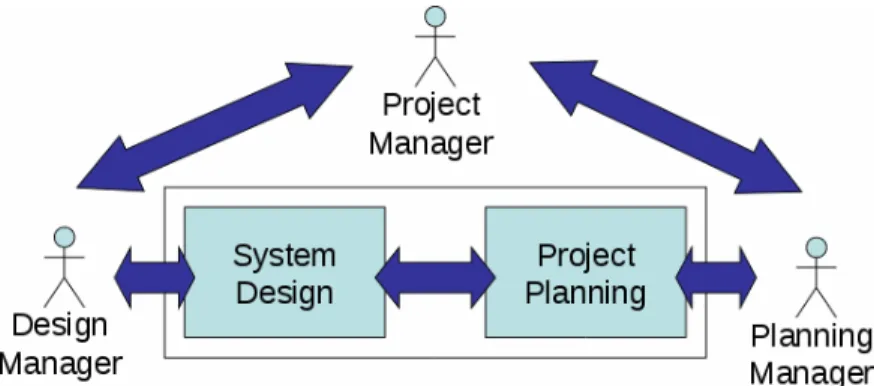
In order to state the global context of our study, it is considered that a project (associated to a system to design) is on the responsibility of a project manager, i.e. the highest person in the hierarchy, as shown in Fig. 1. The project manager inter-acts with (i) a design manager who works within a design system environment and (ii) a planning manager who works within a project planning environment. The difficulty to design the system as well as the complexity of the associated project leads to decompose them linearly and hierarchically. In such case, systems can be decomposed into sub-systems leading to decompose associated development pro-jects into associated (more exactly coupled) sub-propro-jects. The corollary is that complex projects can be decomposed into sub-projects leading to decompose the coupled system in the same manner. Therefore, at each level of the hierarchy, the interactions illustrated on figure 1 can be observed. In this context, the project manager, at his level, can be seen as a “coupling manager” who gives orientations, makes decisions and defines decision frames for the two other parts, taking into account integrated information on dashboards.
The objective of this article is to present, on one hand, the integrated model that supports coupling between system design and project planning environments and, on the other hand, to formalize an adapted process dedicated to this coupling. In the second section, the background of this study is presented according to existing methods and standards. In the third section, the proposed integrated model able to support coupling is exposed and in the fourth section, the generic process for sys-tem design is illustrated by considering an innovative design context.
2 Background
2.1 Definition of Design and Planning Processes
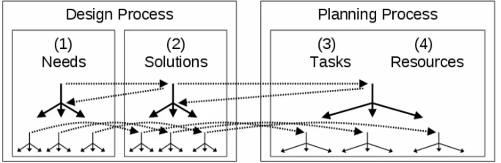
The “design process” proposed in this article is structured following four parts: (i) the definition and\or the specification of the requirements, ii) the identification of the technical solutions which can fill these requirements, iii) the associations re-quirements / solution and, (iv) according to the complexity, the decomposition of the design process until a certain level of abstraction (as shown in the left part of Fig. 2). According to the level of detail of these activities, the proposed design process is compliant to the typology of (Pahl and Beitz 1996), in a "Conceptual / Embodiment / Detailed” design context. The recursive decomposition of the de-sign process complies with a top-down cycle that "zigzag" between requirements and solutions in compliance with the recommendations of "axiomatic design" pro-posed by (Suh 2001). The result of the design process is then considered as a set of associations (i.e. specified requirements coupled to technological solutions) structured in a hierarchical way. Indeed, specifications of requirements lead to some technological solutions and, when a system is decomposed into many sub-systems, a technological solution for a system leads to the specifications of re-quirements for its sub-systems.
Considering the project planning side, a project is considered as a set of activi-ties or tasks made by resources (technological, human). The different tasks start from the first stages of the design process (specification of the requirements at the beginning of preliminary design) until the last tasks of realization of the product. These last ones differ as the product is a unitary one (tasks of supply of compo-nent, production and delivery to the customer for example) or made in series (tasks of production of the first validated series for example).
A planning process is composed of the following activities: (i) the definition of the tasks of the design project, (ii) the estimation of durations and resource needs, (iii) the organization of these tasks and their monitoring (iv) the recursive decompo-sition of some tasks into sub tasks until a certain level of abstraction (as shown in the right part of Fig. 2). The proposed planning process (see section 3.2) is directly in-spired by the “Project Time Management” one defined by the "Project Management Institute" (PMI 2004) which gathers six activities: identification, sequencing, estima-tion of resources and duraestima-tions, organizaestima-tion or elaboraestima-tion of the schedule, followed by the studies or the updating of the schedule. It is also based on engineering system standards and more particularly on the EIA-632 standard (AFIS 2005). This stan-dard identifies five major processes and a top-down approach of the refining design in a recursive way using "building blocks" corresponding to the association of re-quirements and solutions. The result of the planning process can be considered as a set of associations (tasks, resources) structured in a hierarchical way. Indeed, a task can be decomposed into many sub-tasks.
2.2 Interaction between Design and Planning Processes
The axiomatic design and the previous standards allow identifying four interacting domains: (i) the requirements or specifications, (ii) the solutions, (iii) the tasks or ac-tivities and, (iv) the resources. The first two domains are relative to the system de-sign process and the last two domains to the project planning process. Although there are few studies about this coupling problem, one can mention: (i) the studies initialized at M.I.T (Eppinger et al. 1991) about the use of methods and techniques used on product design in order to facilitate the project design. They are at the origin of scientific developments around DSM (Design Structure Matrix), as those of (Lin-demann 2007). The interactions between the four identified domains are defined; (ii) in the same way, the axiomatic design, proposed by (Suh 2001), identifies various domains (Customer Needs, Functional Requirements, Design Parameters and Proc-ess Variables) and makes them interacting. An example of implementation is pre-sented in (Goncalves-Coelho 2004). The interactions between domains are clearly defined: design towards planning but also planning towards design; (iii) another ap-proach, introduced by (Gero 1990), proposes models based on three domains: Func-tion, Behavior and Structure (FBS). The aim of this study is to take into account the product behavior (expected and effective) and to inventory in a formal way eight sub-processes of design. However, tools for interactions between processes are not considered explicitly; (iv) a study very close to the problem addressed has been pro-posed by (Stewart and Tate 2000) who were interested in the coupling of axiomatic design with project planning in the case of the software engineering. Their idea was to associate design variables with tasks of the development process. This approach was implemented with an ad hoc development coupled with Microsoft Project soft-ware package and tested in the case of softsoft-ware engineering.
All these studies indeed confirm the four reserved domains (requirements, solu-tions, tasks and resources) and the existence of causal links that involve interac-tions between these four domains. On the other hand, except in (Stew-art and Tate 2000), there is a lack of tools to support or aid interactions between both design and planning processes.
3 Proposition of an Integrated Model
The integrated (meta-)model proposed in this section is inspired by the EIA-632 engineering standard (AFIS 2005). It is proposed with the objective to develop an integrated computer aided design/planning tool (EIA-632 meta-model is further a high level model describing processes and entities). It consists of three modules: a system design module, a project planning module and a coupling and monitoring module. In order to simplify links between system design entities and project planning entities, we consider that an entity from the system design module is linked, via the coupling module, to one and only one entity from the project plan-ning module and vice versa. The three modules are described in the three follow-ing sections usfollow-ing UML formalism.
3.1 System Design Module
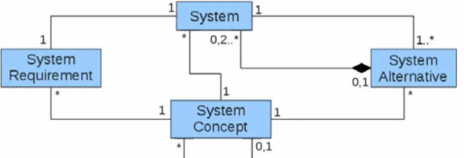
The main entity of the system design module is the system that is associated to a
system concept. A system is associated to (at least) two entities: (i) the system
re-quirement and (ii) one (or many) system alternative(s) as shown in Fig. 3.
A system concept permits to characterize a system. A set of system concepts permits to build the domain ontology, i.e. a hierarchical classification of concepts. The most general concept is the "Universal" one. The ontology is defined using a tree of system concepts. The lowest concepts of the hierarchy are the most special-ized ones and the highest the most general. A concept of the ontology is described by a set of variables used to characterize a system. A concept is associated to its own variables and it also inherits those of its ascendants. The association of a con-cept to a system permits to associate automatically appropriate design variables to this system in order to: (i) define the requirements and (ii) characterize the solu-tions. Therefore, a concept is also associated to a system alternative entity.
The system requirement entity gathers all the technical requirements declined from needs (the expression by means of text of the stakeholders’ requirements or the specifications stemming from the upper level if it exists). A technical
require-ment is defined by a variable, either coming from the concept or defined by the designer, and a unary constraint. For instance, the need corresponding to “the
component C must be as light as possible” can be translated into the system
re-quirement R1: weight of C in [10gr, 20gr].
A system alternative represents one solution for filling the system requirements. It is composed of a logical solution and a physical solution. The logical solution allows to describe the principles of functioning of the associated system and per-mits the hierarchical decomposition if needed. When decomposition is required, a logical solution (then, an alternative) is composed of, at least, two sub-systems. When the difficulty to design is considered as acceptable, the decomposition is stopped (no sub-systems). The physical solution allows the description of the physical components needed for the alternative. It is defined by a list of pairs (de-sign variable, value) describing the solution and a list of physical components that can be built, supplied or sub-contracted. The variables come from the concept of the alternative and from the system requirements. The values given to these vari-ables can be either singleton value, if the solution is certain and totally known or intervals if the solution is not complete or uncertain. For instance, if the material chosen for the component C is carbon, its weight will be between 10gr and 12gr depending of its shape S1: weight of C in [10rg, 12 gr].
3.2 Project Planning Module
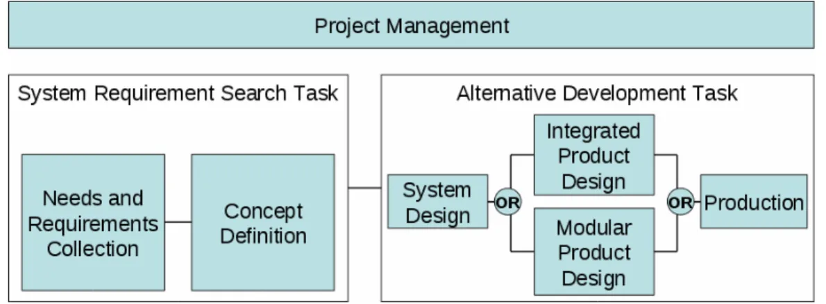
A generic project process (as shown in Fig. 4a) has been extracted from the EIA-632 standard (AFIS 2005) that is going to be defined and planned.
Fig. 4a Generic design project process
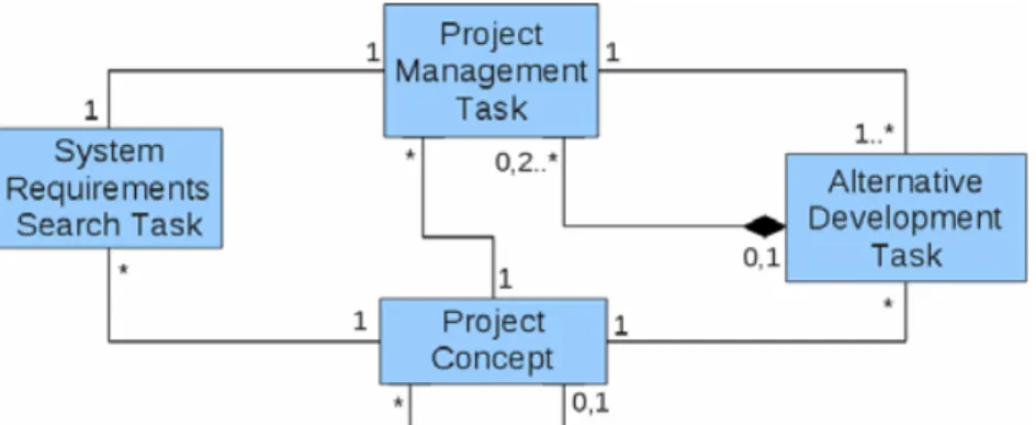
The main entity of this generic project is the project management task that is associated to a project concept. This task is associated to (i) a System
Require-ments Search task (SRS) and (ii) one or many alternative development task(s), as
shown in Fig. 4b. The project management task is driven by the project manager and corresponds to the definition of the objectives and constraints, and to the man-agement of the whole design project. It is then active all along the design process.
The project concepts are similar to the system concepts. A project concept per-mits to characterize a same kind of projects (plane design project for instance) by a same set of variables, such as the duration of the task, its cost and the associated risk. The project concepts are gathered into an ontology of hierarchical project concepts defining the project domain. Each concept in the hierarchy inherits the variables of its ascendants. Therefore, each project requirement is defined using a
unary constraint (one variable and its upper and lower bounds). Then, as the pro-ject planning is performed, propro-ject variables get numeric values corresponding to the progress of the project.
The System Requirement Search task (SRS) corresponds to the selection of the system concept, to the record of the needs and requirements and to the search of the different design alternatives. This task is associated to a project concept in or-der to be characterized with specific indicators.
Fig. 4b Simplified project planning model
One alternative development task corresponds to the management of the design of one system alternative. For the same reason, it is also associated to a project
concept. That task can be carried out in two different ways depending on the
com-plexity of the corresponding system: if the system is simple enough and does not need to be split into sub-systems, the integrated system design path is chosen, oth-erwise, the modular system design path is chosen. In this second case, the modular system design task becomes a macro-task that is decomposed into at least two sub-projects according to the same decomposition of the system into sub-systems. When all the components are designed, their integration has to be done, followed by the validation of the whole system.
3.3 Coupling and Monitoring Module
The coupling and monitoring module has been created in order to facilitate interactions between the system design and the project planning modules. These interactions are directly associated to the level of available knowledge. In this paper, only methodological knowledge, based in our case on PMI and EIA-632 standard, is available: we place ourselves in a case of innovative design where neither information nor knowledge concerning the design project exist.
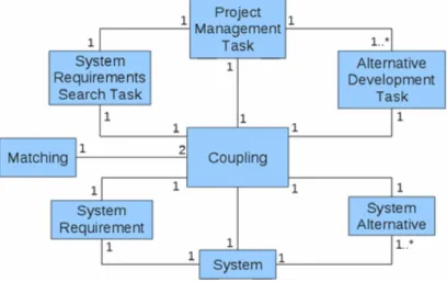
The first goal of the coupling and monitoring module is to insure coupling of design and planning entities. In this article, we make the assumption that, a system entity is associated to one and only one planning entity and reciprocally, and that a system alternative has its own alternative development task and vice-versa. These assumptions permit us to automate the creation of an entity when another is cre-ated in the other environment (e.g. a system is automatically crecre-ated when a pro-ject is created and reciprocally). This coupling module creates specific IDs for each entity and matches them: (i) a system id with a project management task id,
(ii) a system requirement id with a SRS task id and, (iii) a system alternative id with an alternative development task id as shown in Fig. 5a.
Fig. 5a Coupling module
These links between system and project entities allow, in case of innovative de-sign, to memorize the different associations in order to facilitate the monitoring of design processes. When the project has been realized and the design is ended, eve-rything is capitalized in the database and it can be reused for a new design project. When many designs have been performed, it can be possible to get generic rules about a specific type of project and design. A representation by constraints satis-faction problem is proposed in case of routine design in (Aldanondo et al. 2009) and (Vareilles et al. 2008).
The monitoring concerns three kinds of variables: (i) system variables, (cf. sec-tion 4.1) corresponding to the variables of the system ontology, (ii) project
vari-ables (cf. section 4.2) corresponding to the variables of the project ontology and,
(iii) monitoring variables that permit to monitor the system design and the project planning by giving an idea on the progress of the both side.
Fig. 5b Instance of a coupling dashboard
These variables and their values (expected or obtained) can be used to build a coupling dashboard that gathers system design and planning information, as shown in Fig. 5b. This dashboard can be used by the three actors in a verification way (Checking the compliance against requirements: have you done the job
right?), in a validation way (Check the satisfaction of stakeholders: have you done
the right job?), in a controlling way (What are the progress reports in design and
planning?) and in a selecting way in case of system alternatives or alternative de-velopment tasks (Which alternative is the best according to me and to the other side?).
4 Proposition of a Simple System Creation Process
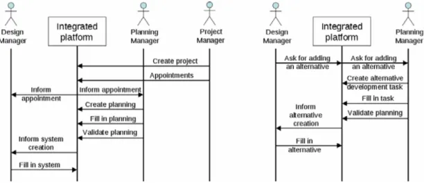
This section illustrates our propositions of methodological coupling. In the case of an ex nihilo system creation (see Fig. 6a), there is no information available about the design project. First of all, a project manager has to be appointed and he has to appoint the design manager and the planning manager. (A) He has to give them the orientations of the project and to define their decisions frames, for instance the global budgets (design and project ones), the delay to conduct the global project and the quantity of resources available. (B) Then, the planning manager instanti-ates a planning from the generic one by giving a delay, affecting the resources to each task and by planning his project. When the planning matches all his project constraints, he has to inform the designer, via the coupling module that his staff can start working. A system (including system requirements and a system
alterna-tive) is then automatically created and the design manager is informed about this creation.
Fig. 6a System creation and Alternative creation sequence diagrams
(C) At this moment, the design manager can choose to investigate different so-lutions or system alternatives (see Fig. 6b): (i) the design manager informs the planning manager that he wants to explore another design alternative, (ii) the planning manager validate (or invalidate) it by creating a new alternative devel-opment task, defines it, plans it and confirms that it fulfills project requirements (delay and availability of resources). After the confirmation, a system alternative is added to the system module and the design job for the investigated solution can start.
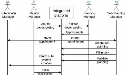
Fig. 6b Sub-system creation sequence diagram
(D) Sometimes, it appears that a system alternative is too complex to be de-signed, so the design manager has to split it into several sub-systems. In this case, (i) the design manager informs the planning manager that he wants to decompose his system into x sub-systems, (ii) the planning manager validates or not this re-quest by the analyze of his project constraints (time and availability of resources). A discussion between project and design managers and the use of the coupling dashboard can be helpful for this kind of decision. If it is possible to create projects, the planning manager becomes the project manager for these sub-projects: he has to appoint all the sub-planning and sub-design managers (as many as sub-systems) and to give them all orientations and their decisions frames for this new level as previously explained in the (A) sub-section. A complete coupling process (instantiating the project, planning it, investigating different solutions, adding system alternatives) can restart.
5 Conclusion and Further Studies
The aim of this article has been to propose an architecture able to support a cou-pling between design process and planning process. We have firstly presented the context of our study, and secondly the background of this study. We have defined what we mean by design process and planning process and we have highlighted the first studies about the coupling of design process and project planning.
On these studies and some standards, we have proposed our definitions of sys-tem design and project planning by the use of ontologies. We have then presented a way of coupling these two processes by making the assumption of a complete bi-jection between the design entities and the project entities. We have also intro-duced the notion of coupling dashboard which gathers information from the de-sign and the project sides in order to help both parts to make the better decision. The support coupling model is finally presented and one of the way of using our
tool is illustrated on a simple example where only a methodological coupling knowledge is available.
The development of the tool based on these assumptions is going to start in few months. The complete tool will be able to link system design and project planning by using different types of knowledge: methodological knowledge as presented here, contextualized knowledge stored in a data base and usable via a Case-Base Reasoning tool and formalized knowledge stored as a Constraint Based model (Aldanondo et al. 2009).
Acknowledgments
The authors wish like to thank their partners in the ATLAS project, the French National Research Agency (ANR) and the 7th Strategic Activity Domain (Archi-tecture and Integration) of Aerospace Valley for their involvement in this project.
References
AFIS, Processes for engineering a system EIA-632 (2005), http://www.afis.fr/doc/normes.normes3.htm
Aldanondo, M., Vareilles, E., Djefel, M., Gaborit, P., Abeille, J.: Coupling product configuration and process planning with constraints. In: INCOM 2009 (2009) Brown, D.C., Chandrasekaran, B.: Expert systems for a class of mechanical design activity.
Knowledge Engineering in Computer-Aided Design, pp. 259–282. North-Holland, Am-sterdam (1985)
Eppinger, S., Whitney, D., Smith, R., et al.: Organizing the tasks in complex design pro-jects. In: MIT Workshop on CAOPD. Springer, New York (1991)
Gero, J.S.: Design prototypes: a knowledge representation schema for design. AI Maga-zine 11(4) (1990)
Goncalves-Coelho, A.: Axiomatic Design and the Concurrent Engineering Paradigm. In: Proc. of COSME, Brasov Roumanie (2004)
Lindemann, U.: A vision to overcome “chaotic” design for X processes in early phases. In: Int. Proc. of Conference on Engineering Design (ICED), Paris France (2007)
Pahl, G., Beitz, W.: Engineering Design A Systematic Approach. Springer, Heidelberg (1996)
PMI Corporate Author. A Guide to the Project Management Body of Knowledge: (Pmbok Guide). Project Management Institute (2004)
Stewart, D., Tate, D.: Integration of Axiomatic design and project planning. In: Proc. of first Int. Conference on Axiomatic Design, Cambridge, USA (2000)