HAL Id: hal-01168667
https://hal.archives-ouvertes.fr/hal-01168667
Submitted on 26 Jun 2015
HAL is a multi-disciplinary open access
archive for the deposit and dissemination of
sci-entific research documents, whether they are
pub-lished or not. The documents may come from
teaching and research institutions in France or
abroad, or from public or private research centers.
L’archive ouverte pluridisciplinaire HAL, est
destinée au dépôt et à la diffusion de documents
scientifiques de niveau recherche, publiés ou non,
émanant des établissements d’enseignement et de
recherche français ou étrangers, des laboratoires
publics ou privés.
A Novel Dynamic Inter-Cell Interference Coordination
Technique for LTE Networks
Mohamad Yassin, Youssef Dirani, Marc Ibrahim, Samer Lahoud, Dany
Mezher, Bernard Cousin
To cite this version:
Mohamad Yassin, Youssef Dirani, Marc Ibrahim, Samer Lahoud, Dany Mezher, et al.. A Novel
Dynamic Inter-Cell Interference Coordination Technique for LTE Networks. IEEE 26th Annual Int.
Symp. Personal, Indoor, and Mobile Radio Communications, Aug 2015, Hong Kong, China. pp.1380
- 1385, �10.1109/PIMRC.2015.7343514�. �hal-01168667�
A Novel Dynamic Inter-Cell Interference
Coordination Technique for LTE Networks
Mohamad Yassin
∗‡, Youssef Dirani
∗§, Marc Ibrahim
∗, Samer Lahoud
‡, Dany Mezher
∗, Bernard Cousin
‡∗Saint Joseph University of Beirut, ESIB, Campus des Sciences et Technologies, Mar Roukoz, Lebanon ‡University of Rennes 1, IRISA, Campus de Beaulieu, 35042 Rennes, France
§Lebanese University, EDST, Faculty of Engineering, Hadath, Lebanon
Abstract—Inter-cell interference problems arise in dense frequency reuse networks such as Long Term Evolution (LTE). They have harmful impact on system performance, especially for cell-edge users or users having bad radio con-ditions. Inter-Cell Interference Coordination (ICIC) schemes aim at mitigating the interference produced by nearby cells to enhance the performance of cell-edge users. ICIC techniques include static frequency reuse schemes and cell-coordinated schemes. In this paper, we propose a semi-static frequency allocation algorithm that exploits evolved-NodeBs communications via X2 interface to mitigate inter-cell interference. Each inter-cell is divided into two zones: inter- cell-center and cell-edge. Cell zone satisfaction is tracked, and the unsatisfied zone gets more frequency resource blocks in a distributed manner. The scope of this work is on the downlink of LTE networks using frequency division duplex transmission mode. An LTE downlink system level simulator is chosen to compare the performance of the proposed technique with the frequency reuse-1 model and the fractional frequency reuse technique. Simulation results show that our technique improves throughput cumulative distribution function, achieves a better throughput fairness, and reduces the percentage of unsatisfied users. It is a dynamic technique able to adapt with non-uniform user distributions and traffic demands.
Index Terms—Inter-cell interference coordination, LTE, fractional frequency reuse, X2 interface, fairness.
I. INTRODUCTION
The motivation behind Long Term Evolution (LTE) of universal mobile terrestrial radio access system is to satisfy User Equipment (UE) demands for higher data rates and Quality of Service (QoS) according to the mobile broad-band standard of the Third Generation Partnership Project (3GPP) [1]. QoS for cell-edge UEs is degraded when the signals transmitted by the neighboring evolved-NodeBs (eNodeBs) interfere with the useful signal transmitted by the serving cell. Thus, the Signal to Interference and Noise Ratio (SINR) is reduced. To avoid the negative impact of Inter-Cell Interference (ICI) on system performance, mitigation techniques are introduced. These techniques in-clude: ICI randomization, ICI cancellation, and Inter-Cell Interference Coordination (ICIC) [2], in addition to beam-forming antenna solutions at the base station. ICI random-ization suppresses ICI at the UE in line with the processing gain. Randomization includes cell specific scrambling, interleaving, and different kinds of frequency hopping. ICI cancellation suppresses the interference spatially by having multiple antennas or by detection/subtraction of the ICI. ICIC, though, is a restriction to the scheduled resources (time, frequency, and power) in order to optimize SINR and cell-edge data rates in the corresponding cell, as well
as to minimize the consumed transmission power, and increase the overall throughput. Literature contains static schemes where frequency and power allocation are fixed on a time scale corresponding to days [2] in a manner that decreases interference. Contrarily to static schemes, cells communicate together in coordinated [3] dynamic schemes, in order to achieve ICI mitigation. Resources are reallocated amongst cells because traffic demands vary in time and space. Many conventional dynamic ICIC schedul-ing schemes focus on fairness and data rate maximization. They are based on maximum SINR which targets the best system throughput, or proportional fairness which targets significant data rates and fairness improvement [4]. In [5], an unsatisfied UE can be the reason for a cell to coordinate resource usage with its neighboring cells. Therefore, indi-vidual UE satisfaction is considered, instead of mean cell zone satisfaction. Downlink power allocation is used in [6] where authors propose a distributed technique to adjust downlink transmission power according to received chan-nel quality indication feedbacks. The proposed technique reduces system power consumption and ICI without any cooperation between network base stations. In [7], authors introduce a decentralized ICIC technique using inter-eNodeB communications via X2 interface. The objective is to optimize Fractional Frequency Reuse (FFR) parameters, in order to increase system throughput. However, only uniform UE distributions are considered when evaluating the performance of the proposed technique.
In this paper, we introduce an ICIC algorithm that adjusts Resource Blocks (RBs) allocation between LTE cells in order to reduce ICI. It also modifies restrictions on RB usage between the different zones of the same cell to fulfill QoS requirements, and to increase throughput fairness. The algorithm, in its essence, is implemented within a scheduler that is meant to work as a super-layer above the LTE scheduler regardless of what that scheduler is (round robin, proportional fair or any other). Algorithm interventions occur when a cell zone is unsat-isfied, or when it needs additional RBs to improve UE satisfaction. Restrictions made on spectrum usage between cell zones guarantee that adjacent cell-edge zones operate on disjoint portions of the available spectrum. System level simulations are used to compare the performance of our technique with the frequency reuse-1 model and the traditional FFR technique.
The rest of the paper is organized as follows. Section II contains a description of existing interference mitigation techniques. Section III introduces the system model and
our novel ICIC algorithm. Section IV describes the LTE downlink system level simulator used, and simulation results are reported in section V. Conclusion is given in section VI.
II. STATICICIC SCHEMES
In this section, we describe the traditional techniques used to mitigate ICI in cellular networks.
A. Reuse-3 Scheme
Global System for Mobile communications (GSM) uses the cellular concept along with frequency reuse-N model to reduce ICI. For each cluster of N adjacent cells, the available spectrum is divided into N portions, where each portion is used only once within the same cluster. For instance, in a system made of three-cell clusters, a set of frequencies used in a cell is not used in the two neighboring cells.
The main disadvantage of such schemes is that spectral efficiency is largely reduced. In fact, only N1 of the available spectrum is used in each cell.
B. Partial Frequency Reuse (PFR)
The whole LTE spectrum, which can be 1.25, 2.5, 5, 10, or 20 MHz [8], is shared among a cluster of three cells. This results in a poor performance for cell-edge UEs. The inner zone of each cell uses the same set of frequencies, and the outer zone of each cell uses a unique set of frequencies, as shown in Fig. 1. We differentiate between the traditional FFR [9], which uses homogeneous power allocation for both inner and outer zones, and the PFR where high transmission power is allocated to the outer zone and low power to the inner zone [3].
Fig. 1: FFR scheme
C. Soft Frequency Reuse (SFR)
Contrarily to FFR [10] and PFR techniques, SFR per-manently uses all the available spectrum in each cell. How-ever, a set of frequencies is allocated a higher transmission power to serve cell-edge UEs in its outer zone. The same spectrum is also used in the inner zone of the neighboring cells, but with a lower downlink power.
TABLE I: Cell States
State Inner Zone Outer Zone 1 Satisfied Satisfied 2 Satisfied Unsatisfied 3 Unsatisfied Satisfied 4 Unsatisfied Unsatisfied
Reuse-3 model guarantees the lowest interference among the mentioned schemes, while SFR shows the high-est interference. However, SFR offers the highhigh-est spectral efficiency, since all the available spectrum is used in each cell [11]. Moreover, reuse-3 scheme is more suitable for low traffic scenarios.
III. ALGORITHMDESCRIPTION ANDSYSTEMMODEL In order to avoid the negative impact of ICI on system performance, we introduce a dynamic ICIC technique that adjusts RB allocation between cell zones, according to UE throughput demands in each zone. It operates in a distributed manner on the downlink of LTE networks. For each cell zone i, we define the satisfaction ratio Qi, as the average ratio of the achieved throughput over the predefined target throughput for active UEs in this zone. When Qi is smaller than one, cell zone i is considered as
unsatisfied, since the achieved throughput is lower than the predefined target throughput. Otherwise, it is considered as satisfied. The following equation shows the satisfaction ratio for cell zone i:
Qi= 1 T × T X t=1 PK(t) k=1 R ef f k PK(t) k=1R target k , (1)
where K(t) is the number of active UEs in the considered zone during the Transmit Time Interval (TTI) t. Ref fk refers to the effective throughput achieved by UE k on the downlink, while Rtargetk (the target throughput of UE k) is the minimum throughput required by this UE. T is the number of TTIs over which the satisfaction ratio is calculated.
Our purpose is to minimize ICI. If the outer zone of a cell is unsatisfied, the concerned eNodeB uses a RB that is not used in the outer zones of the six neighboring cells, if any. Otherwise, the eNodeB orders its neighboring eNodeB(s) to stop using a particular RB, so that it can use it in its outer zone.
An outer zone, originally allocating a particular RB, can deliver it to the requesting cell if it remains satisfied after delivering it. Based on equation (1), our algorithm aims at improving throughput fairness between UEs. A minimum target throughput is given for UEs of the inner and the outer zones. Cell zone satisfaction is monitored every TTI by the eNodeB. Four different cell states exist, and they are listed in Table I. An eNodeB needs to act if any of its zones is unsatisfied e.g., in states 2, 3, and 4. However, when the satisfaction ratio of its inner and outer zones is higher than one, it does not need any additional RB.
When a cell decides to use a new RB, it requests information about RB allocation and satisfaction ratio from its six neighboring cells. Our proposed algorithm
Fig. 2: ICIC flow chart
is distributed, and it operates according to the following communication flow:
1) A cell, having its inner or outer zone unsatisfied, sends an Information Request Message to its six neighboring cells asking them to reply back. 2) Each cell replies back with the RB allocation and the
satisfaction ratio of its inner and outer zones. 3) The middle cell, receiving the information from its
neighbors, performs a computation to decide: a) which RB(s) to take?
b) which cells will be delivering this or these RBs? It might even find out that it cannot use any additional RB.
4) It sends a Done message to its neighbors. In case it decided to use additional RBs, it attaches to the Done message an order to the concerned cells to stop using the RBs in theirs outer zones.
5) The six cells obey the order if any, and the signaling ends.
We note that from the time the six cells receive the information request message at step 1 until step 5, none of them is allowed to initiate a communication. After step 5, any cell can initiate another communication flow if any of its zones is unsatisfied. To prevent oscillation, it is a good practice to forbid a cell that started using additional RBs, or that has just asked for RBs from initiating another communication before a given period of time. This delay allows the considered cell to update the satisfaction ratio of its unsatisfied zone, before generating another communication flow.
In step 3, the unsatisfied cell searches for RBs that are not used in the neighboring zones. Nevertheless, if it has to use RBs that are already used in the neighboring cells, it should make sure that the delivering zones are more satisfied than the cell zone that initiated the communi-cation flow. It is up to the middle cell to estimate the satisfaction ratio of the delivering cell i after delivering one RB (Qdeli), using the information it receives from its neighbors in step 3. Qdeli is calculated as shown in the following equation:
Qdeli= Qi×ni− 1 ni
, (2)
where Qiand niare the satisfaction ratio of the cell zone i
and the number of RBs used by this zone before delivering any RB, respectively. If Qdeli ≥ 1, the middle cell is allowed to use the RB in question.
The middle cell can even request more than one RB from its neighboring cells. Let m be the number of RBs to borrow. In this case, the estimated satisfaction ratio of the neighboring cell i is given by:
Qdeli= Qi×ni− m ni
. (3)
The estimated satisfaction ratio of a cell zone i that uses m additional RBs is given by:
Qacqmi = Q i ×ni+ m ni , (4) where Qiand n
iare the satisfaction ratio of the cell zone i
additional m RBs, respectively.
The ICIC flow chart of our proposed algorithm is given in Fig. 2. Communication flow initiated by an eNodeB is driven either by the inner zone or by the cell-outer zone. When the cell-outer zone of a cell initiates a communication flow, and when there are several candidate RBs to be acquired from the outer zones of the neighboring cells, the eNodeB calculates the willingness ratio QWj of
each RB j to be delivered by the neighboring cells. When the number of cell-outer zones using the candidate RB increases, the willingness of the eNodeB to allocate this RB to its outer zone decreases. The willingness ratio is given by: QWj = 1 PI i=1θij × PJ j=1 PI i=1θ i j J , (5a) θji = (
1, if RB j is used by cell zone i
0, otherwise , (5b) J is the total number of candidate RBs, and I is the number of delivering outer zones. We note that the inner zone of the middle cell may be considered along with the outer zones of the neighboring cells in case it also uses the candidate RB.
A cell zone might need to use an additional RB j among several RBs that are already used in the cell-outer zones of the neighboring cells. In this case, the choice of the most adequate RB depends on the satisfaction ratio of the neighboring cell zones that are using this RB. For a cell zone i, we define Qij as the ability to stop using RB j.
It depends on the satisfaction ratio Qi of cell zone i, and on the maximum satisfaction ratio of the neighboring cell zones that are using RB j. The higher the ratio Qij is, the
more the cell zone i is willing to deliver the RB j. It is given by: Qij = Q i− Qacq max I (Q i) − Qacq, (6)
where Qacq is the satisfaction ratio of the middle cell outer zone that initiates the communication flow, and I is the set of cell-outer zones that are using the RB j. In addition, the more the cell zone remains satisfied after it stops using a given RB, the more it has willingness to do it, in comparison with the other cell zones in the set I. This can be seen through the following expression:
π 2− arctan( Qi ni) max I ( π 2− arctan( Qi ni)) ,
where ni is the number of RBs used in the cell zone i.
This term refers to the slope of the function given in equation (3).
The willingness Wji, del of cell zone i to stop using a RB j is therefore given by:
Wji, del = γ.Qij+ (1 − γ). π 2− arctan( Qi ni) max I ( π 2− arctan( Qi ni)) , (7)
where γ is a weight factor > 0.5, since the willingness of a cell zone to stop using one or more RBs strongly relies on its satisfaction ratio. For each candidate RB j, we define Wdelj as the arithmetic mean of the willingness for all the cell zones that are using this RB. It is given by:
Wdelj = PI i=1W i, del j I . (8)
The willingness Wjacq to use an additional RB j by the outer zone of the cell that initiates a communication flow is therefore given by:
Wjacq = QWj× W
del
j . (9)
Now we determine the time period over which the satisfaction ratio Qi is calculated, which is T × TTI.
This value could be initially any random number in the order of a one way communication delay via X2 interface between adjacent eNodeBs e.g., 10 ms. If Qi is close to
one, this might have a negative impact on the algorithm. T should be increased to avoid generating meaningless communication flows. For instance, if the satisfaction level of a particular zone becomes greater than one after three communication delays (which is the necessary time for the communication flow to take place), then T should be increased, in order to optimize inter-eNodeB communi-cations. We note that at the communication initiation, a neighboring cell may also initiate another communication simultaneously. To resolve the contention caused by com-munication delay, a backoff is required for both cells. Each cell waits for a randomly chosen time before initiating another communication flow. Meanwhile, a cancel request message is sent to the neighboring cells, in order to remove the restrictions made on communication initiation after receiving the information request message.
IV. SIMULATIONENVIRONMENT
An LTE downlink system level simulator [12] devel-oped by Vienna University of Technology is chosen to perform our simulations. ICI mainly affects cell-edge UEs, since their downlink useful signals receive higher path loss, and they receive important interfering signals from the neighboring cells. Our objective is to compare the performance of the proposed dynamic ICIC technique with that of the frequency reuse-1 model and the static FFR technique. Frequency reuse-1 model is used, since LTE allows the utilization of all the available spectrum in each cell. We integrated our proposed ICIC algorithm as well as a dynamic power allocation strategy, since only homogeneous power allocation was supported for reuse-1 and traditional FFR techniques. Simulation parameters are given in Table II.
Operating bandwidth equals 5 MHz. Thus, 25 RBs are available in each cell. Path loss model is TS 25.814, which is the same as in High Speed Downlink Packet Access (HSDPA) networks. Feedback delay is the average time required to transmit feedbacks about wideband downlink channel state form UEs to their serving eNodeB. Rtargetj is the target throughput or the minimum throughput required for UE j. Two different values are defined for cell-center and cell-edge UEs. Adaptive modulation and coding
TABLE II: Simulation Parameters Parameter Value Cell geometry Hexagonal Inter-eNodeB distance 500 m
Operating bandwidth 5 MHz Number of RBs 25 Transmission frequency 2 GHz
Bandwidth per RB 180 kHz Transmit time interval 1 ms
Pathloss model TS 25.814 Thermal noise density -174 dBm/Hz
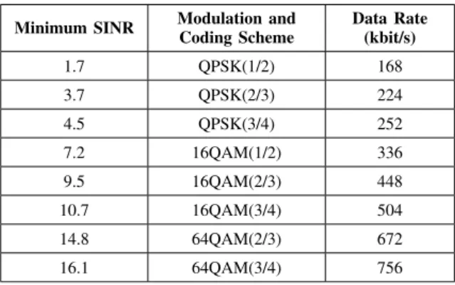
Feedback delay 3 ms Scheduler Round Robin Traffic model Full buffer eNodeB maximum power 20 W Target throughput (Rtargetj ) 400 kbit/s, 500 kbit/s TABLE III: SINR-Data Rate Mapping Table Minimum SINR Modulation andCoding Scheme Data Rate(kbit/s)
1.7 QPSK(1/2) 168 3.7 QPSK(2/3) 224 4.5 QPSK(3/4) 252 7.2 16QAM(1/2) 336 9.5 16QAM(2/3) 448 10.7 16QAM(3/4) 504 14.8 64QAM(2/3) 672 16.1 64QAM(3/4) 756
function that maps SINR to achievable data rate per RB is given in Table III.
We use Jain’s fairness index [13] to evaluate the fairness of UEs throughputs. It is given by:
J (x1, x2, ..., xK) = ( K P k=1 xk)2 K. K P k=1 x2 k , (10)
where J rates the fairness of a set of throughput values; K is the number of UEs; xk is the throughput of UE k.
Jain’s fairness index ranges from K1 (worst case) to 1 (best case). It reaches its maximum value when all UEs receive the same throughput.
V. SIMULATIONRESULTS ANDDISCUSSION Extensive simulations are made to compare the perfor-mance of our ICIC technique with the frequency reuse-1 model and the FFR scheme. Results concerning through-put cumulative distribution function, throughthrough-put fairness index, and UE satisfaction are reported in the following. A. Throughput Cumulative Distribution Function
The simulated network consists of 19 adjacent LTE cells, where 188 UEs are randomly placed within the entire network. Simulation time is 1000 TTIs for our
dynamic ICIC technique, and a new communication flow is launched when at least one zone of an LTE cell is unsatisfied. Simulations are repeated 100 times, where UE positions and radio conditions are randomly gener-ated each time, and the obtained throughput Cumulative Distribution Function (CDF) is illustrated in Fig. 3.
0 1 2 3 4 5 6 0 0.2 0.4 0.6 0.8 1 Throughput [Mbit/s] CDF Reuse−1 FFR Dynamic ICIC
Fig. 3: Throughput cumulative distribution function For a given throughput value, CDF represents the prob-ability to find a UE characterized by a lower throughput. The lower the CDF is, the better the QoS is. Our dy-namic ICIC technique shows a lower throughput CDF for throughput values less than 0.75 Mbit/s when compared to the frequency reuse-1 model. It also shows a lower CDF for throughput values less than 1.25 Mbit/s when compared to FFR. Therefore, our proposed scheme suc-ceeds in reducing the number of UEs characterized by low throughputs. The percentage of UEs having throughputs higher than 1 Mbit/s is decreased in comparison with the frequency reuse-1 model, since RB allocation is adjusted to the benefit of unsatisfied UEs.
B. Fairness Index
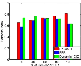
We also simulate a network of 19 adjacent hexagonal LTE cells with 188 UEs randomly placed across the different cells. We generate UEs with uniform and non-uniform distributions between inner and outer zones. The percentage of cell-inner UEs designates the percentage of UEs in the cell-center zone. For each UE distribution, simulations are repeated 100 times, and results are shown in Fig. 4.
It is shown that when the majority of active UEs are located in the outer zone, our dynamic ICIC technique outperforms the reuse-1 model and the FFR scheme. Thus, it improves throughput fairness for the entire network when the majority of UEs are facing ICI problems. How-ever, when the majority of UEs are having good radio conditions, reuse-1 model guarantees the highest through-put fairness. In this case, cell zones are satisfied, since the majority of the UEs are characterized by high SINR values. Restrictions on RB usage and power allocation, imposed by ICIC techniques to mitigate interference are no longer useful in comparison with reuse-1 model that allows using all the spectrum at the maximum available transmission power. Nevertheless, Jain’s fairness index of
20 40 60 80 100 0 0.2 0.4 0.6 0.8 1 Fairness Index % of Cell−Inner UEs Reuse−1 FFR Dynamic ICIC
Fig. 4: Fairness index versus percentage of cell-inner UEs
our dynamic ICIC technique is permanently higher than or equal to that of FFR, since it is able to adapt with uniform and non-uniform UE distributions.
C. UE Satisfaction
We define the percentage of unsatisfied UEs as the percentage of active UEs with mean throughputs less than 512 kbit/s. We assume that this is the minimum through-put required to guarantee an acceptable QoS. The same scenario as in the previous paragraph is simulated, and the average results showing the percentage of unsatisfied UEs versus UE distribution are reported in Fig. 5.
20 40 60 0 5 10 15 20 25 30 % of Unsatisfied UEs % of Cell−Inner UEs Reuse−1 FFR Dynamic ICIC
Fig. 5: UE satisfaction versus UE distribution
According to these results, we notice that our technique always shows the lowest percentage of unsatisfied UEs in comparison with the frequency reuse-1 model and the FFR technique. In fact, it adjusts RB allocation not only between cell zones, but also between network cells in order to satisfy UE demands in each zone. The main disadvantage of FFR lies in its static aspect for RB allocation. Although a portion of the available spectrum is exclusively allocated for the cell-outer zone, FFR does not adjust RB allocation to satisfy throughput demands in this zone, especially when throughput demand increases.
We note that the percentage of unsatisfied UEs equals zero for all the compared techniques when the majority of the active UEs are cell-inner UEs.
VI. CONCLUSION
In dense frequency reuse networks, such as LTE, inter-cell interference problems have a negative impact on UE throughput and system performance. ICIC techniques are required to increase UE throughput, and to improve quality of service especially for cell-edge UEs. For instance, FFR adjusts RB distribution between cell zones in order to reduce ICI. SFR scheme mitigates ICI without reducing the spectral efficiency.
In this paper, we proposed a dynamic ICIC algorithm that adjusts RB allocation between cell zones according to throughput demands in each zone. Our algorithm targets minimum QoS to UEs within the inner and the outer zones of a cell. RB allocation between LTE cells or even between cell zones, is performed dynamically in order to satisfy UE demands and QoS requirements. Simulation results show that our technique improves throughput CDF and reduces the percentage of unsatisfied UEs in the network. It also increases throughput fairness among active UEs when the majority of them are located in the cell-outer zone.
REFERENCES
[1] 3GPP. Third Generation Partnership Project. [Online]. Available: http://www.3gpp.org/technologies/keywords-acronyms/98-lte [2] ——, “Physical Layer Aspects for Evolved Universal Terrestrial
Radio Access (UTRA) (Release 7),” 3GPP TR 25.814 version 7.1.0, Tech. Rep., 2006.
[3] A. Hamza, S. Khalifa, H. Hamza, and K. Elsayed, “A Survey on Inter-Cell Interference Coordination Techniques in OFDMA-Based Cellular Networks,” IEEE Commun. Surveys Tutorials, vol. 15, no. 4, pp. 1642–1670, 2013.
[4] H. S. Kim and D. H. Kim, “Dynamic Inter-Cell Interference Coor-dination and Dynamic Resource Allocation Scheduling Schemes for Inter-Cell Interference Mitigation in 3GPP LTE,” Int. J. Innovative Computing, Information and Control, vol. 7, no. 1, pp. 335–344, January 2011.
[5] S. Zheng, H. Tian, Z. Hu, L. Chen, and J. Zhu, “QoS-Guaranteed Radio Resource Allocation with Distributed Inter-Cell Interference Coordination for Multi-Cell OFDMA Systems,” in IEEE 71st Vehicular Technology Conf., May 2010, pp. 1–5.
[6] M. Yassin, S. Lahoud, M. Ibrahim, and K. Khawam, “A Downlink Power Control Heuristic Algorithm for LTE Networks,” in 21st Int. Conf. Telecommunications, May 2014, pp. 323–327.
[7] D. Kimura, Y. Harada, and H. Seki, “De-Centralized Dynamic ICIC Using X2 Interfaces for Downlink LTE Systems,” in IEEE 73rd Vehicular Technology Conf., May 2011, pp. 1–5.
[8] 3GPP, “LTE Evolved Universal Terrestrial Radio Access (E-UTRA) Radio Frequency (RF) System Scenarios,” ETSI 3GPP TR 36.942, version 11.0.0, Sophia Antipolis, France, Tech. Rep., 2012. [9] M. Rahman and H. Yanikomeroglu, “Enhancing Cell-Edge
Perfor-mance: A Downlink Dynamic Interference Avoidance Scheme with Inter-Cell Coordination,” IEEE Trans. Wireless Commun., vol. 9, no. 4, pp. 1414–1425, April 2010.
[10] N. Hassan and M. Assaad, “Optimal Fractional Frequency Reuse (FFR) and Resource Allocation in Multiuser OFDMA System,” in Int. Conf. Information and Communication Technologies, Aug 2009, pp. 88–92.
[11] A. Hamza, S. Khalifa, H. Hamza, and K. Elsayed, “A Survey on Inter-Cell Interference Coordination Techniques in OFDMA-Based Cellular Networks,” IEEE Commun. Surveys Tutorials, vol. 15, no. 4, pp. 1642–1670, 2013.
[12] J. Ikuno, M. Wrulich, and M. Rupp, “System Level Simulation of LTE Networks,” in IEEE 71st Vehicular Technology Conf., May 2010, pp. 1–5.
[13] R. K. Jain, D. W. Chiu, and W. R. Hawe, “A Quantitative Measure of Fairness and Discrimination for Resource Allocation and Shared Computer System,” Digital Equipment Corporation, Tech. Rep., 1984.