HAL Id: hal-01006892
https://hal.archives-ouvertes.fr/hal-01006892
Submitted on 3 May 2018
HAL is a multi-disciplinary open access
archive for the deposit and dissemination of
sci-entific research documents, whether they are
pub-lished or not. The documents may come from
teaching and research institutions in France or
abroad, or from public or private research centers.
L’archive ouverte pluridisciplinaire HAL, est
destinée au dépôt et à la diffusion de documents
scientifiques de niveau recherche, publiés ou non,
émanant des établissements d’enseignement et de
recherche français ou étrangers, des laboratoires
publics ou privés.
Face stability analysis of circular tunnels driven by a
pressurized shield
Guilhem Mollon, Daniel Dias, Abdul-Hamid Soubra
To cite this version:
Guilhem Mollon, Daniel Dias, Abdul-Hamid Soubra. Face stability analysis of circular tunnels driven
by a pressurized shield. Journal of Geotechnical and Geoenvironmental Engineering, American
So-ciety of Civil Engineers, 2010, 136 (1), pp.215-229. �10.1061/(ASCE)GT.1943-5606.0000194�.
�hal-01006892�
Face
Stability Analysis of Circular Tunnels Driven
by
a Pressurized Shield
Guilhem Mollon
1; Daniel Dias
2; and Abdul-Hamid Soubra
3Abstract: The aim of this paper is to determine the face collapse pressure of a circular tunnel driven by a pressurized shield. The analysis is performed in the framework of the kinematical approach of limit analysis theory. It is based on a translational three-dimensional multiblock failure mechanism. The present failure mechanism has a significant advantage with respect to the existing limit analysis mechanisms developed in the case of a frictional soil: it takes into account the entire circular tunnel face and not only an inscribed ellipse to this circular area. This was made possible by the use of a spatial discretization technique. Hence, the three-dimensional failure surface was generated “point by point” instead of simple use of existing standard geometric shapes such as cones or cylinders. The numerical results have shown that a multiblock mechanism composed of three blocks is a good compromise between computation time and results accuracy. The present method significantly improves the best available solutions of the collapse pressure given by other kinematical approaches. Design charts are given in the case of a frictional and cohesive soil for practical use in geotechnical engineering.
Keywords: Tunnel; Limit analysis; Tunnel face stability; Pressurized shield; Upper-bound method.
Introduction
The stability analysis and the assessment of ground surface settle-ment of a pressurized shield tunneling are of major importance in real shield tunneling projects. The aim of the stability analysis is to ensure safety against soil collapse in front of the tunnel face. This requires the determination of the minimal pressure 共air, slurry, or earth兲 required to prevent the collapse of the tunnel face. On the other hand, the deformation analysis deals with the deter-mination of the pattern of ground deformation that will result from the construction works. These ground deformations should be within a tolerable threshold to prevent damage to surface or subsurface structures. This paper is limited to the first problem, i.e., the face stability analysis of a shallow circular tunnel driven by a pressurized shield. Tunneling under compressed air is con-sidered in the analysis.
The study of the face stability of circular tunnels driven by pressurized shields has been investigated by several writers in literature. Some writers have considered a purely cohesive soil 共Broms and Bennermark 1967; Mair 1979; Davis et al. 1980;
Kimura and Mair 1981; Ellstein 1986; Augarde et al. 2003; Klar et al. 2007; among others兲. In this case, the stability of a tunnel face is governed by the so-called load factor N defined as N =共s+␥H−t兲/cu where s⫽surcharge loading on the ground surface; t⫽uniform pressure applied on the tunnel face; H⫽depth of the tunnel axis; and cu⫽soil undrained cohesion. Broms and Bennermark共1967兲 stated from an experimental ap-proach that the stability is maintained as long as N⬍6–7. Kimura and Mair共1981兲 conducted centrifuge tests and proposed a limit value of N between 5 and 10 depending on the tunnel cover. Later on, Ellstein共1986兲 gave an analytical expression of N for homo-geneous cohesive soils based on a limit equilibrium analytical approach. His results are in good agreement with those by Kimura and Mair 共1981兲. More recently, an interesting numerical ap-proach was proposed by Augarde et al. 共2003兲 using a finite-element limit analysis method based on classical plasticity theory. This promising approach is currently limited to a two-dimen-sional analysis. Finally, Klar et al.共2007兲 have suggested a new kinematical approach in limit analysis theory for the 2D and 3D stability analysis of circular tunnels in a purely cohesive soil. Their method is based on an admissible continuous velocity field. A velocity field that is proportional to a displacement field based on elasticity theory 共e.g., Verruijt and Booker 1996; Sagaseta 1987兲 was suggested by these writers. For the 3D face stability analysis, their numerical results were better than the values pub-lished by Davis et al. 共1980兲 for great values of C/D where C⫽tunnel cover and D⫽tunnel diameter. A somewhat similar ap-proach has been undertaken previously by Osman et al.共2006兲 for the 2D stability analysis of circular tunnels in a cohesive soil. However, the velocity field was based on the empirical Gaussian settlement trough near the ground surface instead of the analytical elasticity equations. For the case of a frictional soil, some writers have performed experimental tests共cf., Chambon and Corté 1994; Takano et al. 2006兲. Others 共Horn 1961; Leca and Dormieux 1990; Eisenstein and Ezzeldine 1994; Anagnostou and Kovari
1
Ph.D. Student, INSA Lyon, LGCIE Site Coulomb 3, Géotechnique, Bât. J.C.A. Coulomb, Domaine scientifique de la Doua, 69621 Villeur-banne cedex, France. E-mail: guilhem.mollon@insa-lyon.fr
2
Associate Professor, INSA Lyon, LGCIE Site Coulomb 3, Géotech-nique, Bât. J.C.A. Coulomb, Domaine scientifique de la Doua, 69621 Villeurbanne cedex, France. E-mail: daniel.dias@insa-lyon.fr
3
Professor, Dept. of Civil Engineering, Univ. of Nantes, Bd. de l’université, BP 152, 44603 Saint-Nazaire cedex, France共corresponding author兲. E-mail: abed.soubra@univ-nantes.fr
1996; Broere 1998; Mollon et al. 2009兲 have performed analytical or numerical approaches. The aim of the centrifuge tests by Chambon and Corté共1994兲 was to visualize the collapse pattern and to determine the value of the critical face pressure. Chambon and Corté共1994兲 showed that the failure soil mass resembles to a chimney that does not necessarily outcrop at the ground surface. An arch effect that takes place above the tunnel face was pointed out by these writers to explain this phenomenon. On the other hand, Takano et al.共2006兲 have performed 1g experimental tests using X-ray computed tomography scanner in order to visualize the three-dimensional shape of the failure mechanism. As in Chambon and Corté共1994兲, a soil failure in the form of a chim-ney that does not necessarily attain the ground surface was pointed out by these writers. Finally, it was suggested that the shape of the failure zone can be simulated with logarithmic spi-rals in the vertical cross sections and elliptical shapes in the hori-zontal cross sections. Concerning the analytical models of a frictional soil, Anagnostou and Kovari共1996兲 and Broere 共1998兲 have used the failure pattern proposed by Horn 共1961兲 to deter-mine the expression of the critical face pressure using the limit equilibrium method. They concluded that this method is quite simple to use but it is based on a priori assumptions concerning the shape of the failure mechanism and the normal stress distri-bution applied to the faces of the moving blocks. A more rigorous model based on the kinematical method of limit analysis was proposed by Leca and Dormieux 共1990兲. This model was then improved by Mollon et al.共2009兲. On the other hand, Eisenstein and Ezzeldine 共1994兲 have performed a numerical study for the stability analysis of a tunnel face using two models共axisymetric and three dimensional兲. They stated that an axisymetric model is not enough accurate and underestimates the value of the critical collapse pressure.
As a conclusion, the kinematical limit analysis models by Leca and Dormieux 共1990兲 and Mollon et al. 共2009兲 are among the most recent and significant approaches. It should be mentioned here that the upper-bound theorem 共kinematical approach兲 states that if a work calculation is performed for a kinematically admis-sible collapse mechanism, then the loads thus deduced will be higher than共or equal to兲 those for collapse. Since the tunnel col-lapse pressure resists the colcol-lapse of soil into the tunnel, it is a negative load in the sense discussed earlier. Thus, the kinematical approach will provide an unsafe estimate of the tunnel pressure required to maintain stability共i.e., smaller or equal to that actually required兲. The aim of this paper is to improve the existing solu-tions given by Leca and Dormieux 共1990兲 and Mollon et al. 共2009兲 in the framework of the kinematical approach. The soil considered in the analysis is assumed to be frictional and/or co-hesive. The main originality of the present work is that the failure mechanism presented herein includes the whole circular tunnel face while the existing mechanisms 关except that developed by Klar et al. 共2007兲 in the case of a purely cohesive soil兴 only involve an elliptical area inscribed to the circular face. This im-provement required numerical generation “point by point” of complex shapes of failure surfaces instead of simple use of exist-ing standard geometric shapes共such as cones or cylinders兲 as it was made in Davis et al.共1980兲, Leca and Dormieux 共1990兲, and Mollon et al.共2009兲. After a short overview of the existing limit analysis failure mechanisms by Leca and Dormieux 共1990兲 and Mollon et al. 共2009兲, the proposed mechanism and the corre-sponding numerical results are presented and discussed.
Overview of Previous Kinematical Limit Analysis Approaches
The problem of computation of the tunnel face collapse pressure c can be idealized as shown in Fig. 1 by considering a circular rigid tunnel of diameter D driven under a depth of cover C. Ac-tive collapse of the tunnel is triggered by application of surcharge s and self-weight, with the tunnel face pressure c providing resistance against failure. Under passive conditions, these roles are reversed, and blow-out of the soil mass in front of the tunnel face is caused by the tunnel pressure with resistance being pro-vided by the surcharge and self-weight. The assumption of a uni-form pressure at the tunnel face may be justified in the present paper where shield tunneling under compressed air is considered in the analysis. In this paper, only the active collapse of the tunnel face is considered in the analysis; the blow-out of the soil in front of the tunnel face being likely of less practical interest. As men-tioned before, several theoretical models have been presented in literature for the computation of the tunnel face collapse pres-sures. The most recent and significant approaches are the ones presented by Leca and Dormieux共1990兲 and Mollon et al. 共2009兲 who considered three-dimensional failure mechanisms in the framework of the kinematical method in limit analysis. The mechanism by Mollon et al.共2009兲 constitutes an improvement of the failure mechanism by Leca and Dormieux 共1990兲 since it allows the three-dimensional slip surface to develop more freely in comparison with the available two-block mechanism given by Leca and Dormieux共1990兲. Both failure mechanisms are briefly described in the following sections in order to facilitate the un-derstanding of the new failure mechanisms developed in the present paper.
The collapse mechanism presented by Leca and Dormieux in 1990 共cf., Fig. 1兲 is composed of two truncated conical blocks with circular cross sections and with opening angles equal to 2 in order to respect the normality condition in limit analysis. The lower conical block has an axis inclined at an angle with respect to the horizontal, and it intersects the tunnel face with a vertical ellipse tangent to the invert and to the crown of the tunnel face. The upper conical block has a vertical axis and it intersects the lower conical block with an elliptical area. In order to ensure the same contact area between both blocks, the inclination of the contact plane between the two blocks is such that the upper block is the mirror image of the lower block with respect to the normal to the area between both blocks 共i.e., plane shown in Fig. 1兲. This is the reason why this mechanism is entirely defined by only one angular parameter. Notice that the assumption of a vertical
axis for the upper block is not adequate and leads to nonoptimal collapse pressures.
The failure mechanism presented by Mollon et al.共2009兲 and described in more detail in Oberlé 共1996兲 is an improvement of the two-block collapse mechanism presented by Leca and Dormieux共1990兲. This mechanism is a multiblock 共cf., Fig. 2兲. It is composed of n truncated rigid cones with circular cross sec-tions and with opening angles equal to 2. A mechanism with n = 5 is presented in Fig. 2. The geometrical construction of this mechanism is similar to that of Leca and Dormieux共1990兲, i.e., each cone is the mirror image of the adjacent cone with respect to the plane that is normal to the contact surface separating these cones. This is a necessary condition to ensure the same elliptical contact area between adjacent cones. In order to make clearer the geometrical construction of the 3D failure mechanism, Fig. 3 shows how the first two truncated conical blocks adjacent to the tunnel face are constructed. The geometrical construction of the remaining truncated conical blocks is straightforward. As for the mechanism by Leca and Dormieux共1990兲, Block 1 is a trun-cated circular cone adjacent to the tunnel face. The intersection of this truncated cone with the tunnel face is an elliptical surface that does not cover the entire circular face of the tunnel. This is a shortcoming not only of the multiblock mechanism by Mollon et al.共2009兲 but also of the two-block mechanism by Leca and Dormieux共1990兲. On the other hand, Block 1 is truncated with Plane 1 which is inclined at an angle1with the vertical direction 共cf., Fig. 3兲. In order to obtain the same contact area with the adjacent truncated conical block, Block 2 is constructed in such a manner to be the mirror image of Block 1 with respect to the plane that is normal to the surface separating the two blocks共i.e., Plane 2 as shown in Fig. 3兲. The mechanism by Mollon et al.
共2009兲 is completely defined by n angular parameters and i 共i=1, ... ,n−1兲 where n is the number of the truncated conical blocks共cf., Fig. 2兲.
Notice finally that the upper rigid cone in the mechanisms by Leca and Dormieux共1990兲 and Mollon et al. 共2009兲 will or will not intersect the ground surface depending on the and C/D values. This phenomenon of no outcropping at the ground surface was also pointed out by Chambon and Corté共1994兲 and Takano et al.共2006兲 while they performed experimental tests: As mentioned before, a failure soil mass which has the shape of a chimney that does not necessarily outcrop at the ground surface was observed by these writers.
Both mechanisms by Leca and Dormieux共1990兲 and Mollon et al. 共2009兲 are translational kinematically admissible failure mechanisms. The different truncated conical blocks of these mechanisms move as rigid bodies. These truncated rigid cones translate with velocities of different directions, which are collin-ear with the cones axes and make an angle with the conical discontinuity surfaces in order to respect the normality condition required by the limit analysis theory. The velocity of each cone is determined by the condition that the relative velocity between the cones in contact has the direction that makes an angle with the contact surface.
The numerical results obtained by Mollon et al.共2009兲 have shown that a five-block共i.e., n=5兲 mechanism was found suffi-cient since the increase in the number of blocks above five blocks increases共i.e., improves兲 the solutions by less than 1%. The im-provement of the solution by Mollon et al.共2009兲 with respect to the one by Leca and Dormieux共1990兲 is due to the increase in the degree of freedom of the failure mechanism by Mollon et al. 共2009兲. Notice however that the solutions by Mollon et al. 共2009兲 and those by Leca and Dormieux共1990兲 suffer from the fact that only an inscribed elliptical area to the entire circular tunnel face is involved by failure due to the conical shape of the rigid blocks; the remaining area of the tunnel face being at rest. This is striking and is contrary to what was observed in numerical simulations. This shortcoming will be removed in the following failure mecha-nisms developed in this paper.
Kinematical Approach for the Computation of the Tunnel Face Collapse Pressure
The aim of this paper is to compute the tunnel face collapse pressure of a shallow circular tunnel driven by a pressurized shield in a frictional and/or cohesive soil. The theoretical model is based on a three-dimensional multiblock failure mechanism in the framework of the kinematical approach of the limit analysis theory. In order to render clearer the theoretical formulation of the multiblock mechanism, the geometrical construction of a mecha-nism composed of a single rigid block is first presented. It is then followed by the presentation of the multiblock mechanism. The one- and multiblock mechanisms developed in this paper will be referred to as improved mechanisms since they allow共1兲 to con-sider the entire circular area of the tunnel face and not only an inscribed ellipse inside this area; 共2兲 to improve the solutions presented by Leca and Dormieux共1990兲 and Mollon et al. 共2009兲 in the framework of the kinematical approach of limit analysis.
Improved One-Block Mechanism M1
M1 is a rigid translational one-block mechanism. It is defined by a single angular parameter 共cf., Fig. 4兲. This angle corresponds
Fig. 2. Multiblock failure mechanism by Mollon et al.共2009兲 共after
Mollon et al. 2009兲
Fig. 3. Detail of the construction of the multiblock failure
to the inclination of the velocity of this block with respect to the longitudinal axis of the tunnel. Since a failure mechanism involv-ing the whole circular area of the tunnel face is explored here, no simple geometrical shape共such as a cone兲 can be considered. It is necessary to generate the three-dimensional failure surface point by point using a spatial discretization technique.
Method of Generation of the Improved One-Block Mechanism
It is assumed共cf., Fig. 4兲 that the cross section of the improved one-block mechanism in the vertical plane 共y,z兲 containing the longitudinal axis of the tunnel is the same as that of the one-block mechanism composed of a single conical block with an opening angle equal to 2. This is to be expected because the conical one-block mechanism involves the entire diameter of the tunnel face only along the vertical diameter of the tunnel face. Referring to the共y,z兲 coordinate system shown in Fig. 4, the z-coordinate of the apex of the mechanism 共i.e., Point A兲 is denoted zmax. In case of no outcrop of the failure mechanism at the ground surface 关cf., Fig. 4共a兲兴, zmaxis given by
zmax= D/关tan共 + 兲 − tan共 − 兲兴 共1兲 Otherwise, the failure mechanism outcrops at the ground surface 关cf., Fig. 4共b兲兴 and zmaxbecomes equal to
zmax=共C + D兲/tan共 + 兲 共2兲 The three-dimensional failure surface of the improved one-block mechanism is determined here by defining the contours of this surface at several vertical planes parallel to the tunnel face共cf., Fig. 5兲. Notice that the contour of a given plane is defined from that of the preceding plane. The first vertical plane to be consid-ered is that of the tunnel face for which the contour of the failure surface is circular as required. The different vertical planes are equidistant; the horizontal distance separating two successive planes being␦z= zmax/nzwhere nz⫽number of slices considered in the spatial discretization of the 3D failure surface along the z-axis 共cf., Fig. 4兲. The vertical planes are denoted by index j where j = 0 , . . . , nz; j = 0 being that of the tunnel face共cf., Fig. 5兲. In the following, the generation of only the first contour共i.e., that cor-responding to j = 1兲 of the failure surface located at a distance ␦z from the tunnel face and using the contour of the tunnel face 共which is circular of diameter D兲 will be presented. The genera-tion of the subsequent contours is straightforward.
The contour of the tunnel face is discretized by a number nof
points Pi,0uniformly distributed along this contour. Point Pi,0 is defined by the parameters 共R,i兲 in the polar coordinate system and by the following coordinates in the共x,y兲 plane corresponding to the tunnel face共cf., Fig. 5兲:
再
xi,0= R · sin共i兲 yi,0= R · cos共i兲冎
共3兲 Thus, each point of the failure surface is defined by two indices i 共index indicating the position of the point in a given vertical plane兲 and j 共index of the vertical plane兲. The generation of point Pi,1in the first contour makes use of three points Pi,0, Pi−1,0, and Pi+1,0belonging to the tunnel face 共cf., Fig. 5兲. The position of point Pi,1must satisfy the three following conditions共cf., Fig. 6兲: • Pi,1belongs to plane j = 1, i.e.
zi,1= zi,0+␦z=␦z 共4兲 • The triangular surface formed by points Pi,0, Pi−1,0, and Pi,1 should respect the normality condition in limit analysis, i.e., the normal to the plane of this triangle should make an angle /2+ with the velocity vector V. This normality condition is necessary for the failure mechanism to be kinematically ad-missible and for the limit analysis theory to be applicable. • The triangular surface formed by points Pi,0, Pi+1,0, and Pi,1
should also respect the normality condition.
(a) (b)
Fig. 4. Cross section of the improved one-block mechanism in the
共y,z兲 plane in two cases: 共a兲 no outcrop of the mechanism at the ground surface;共b兲 outcrop at the ground surface
Fig. 5. Principle of generation of the 3D failure surface by using
several contours parallel to the tunnel face and several points on each contour
Fig. 6. Principle of generation of point Pi,1from point Pi,0located on
The procedure described earlier allows one to create for each point Pi,j a corresponding point Pi,j+1 in the following plane by respecting the normality condition in the neighborhood of Pi,j. The mathematical formulation of this problem can thus be briefly described as follows.
The three points Pi,1, Pi,0, and Pi−1,0 define a plane named 共⌫1兲, with a normal vector N1共which is as yet unspecified兲. Also, vector A1 belonging to the plane j = 0 is defined as: A1
= Pi−1,0Pi,0 where the coordinates of points Pi,0, and Pi−1,0 are given, respectively, by共xi,0, yi,0, zi,0兲 and 共xi−1,0, yi−1,0, zi−1,0兲. Vec-tors N1and A1are given as follows:
N1
冦
xn1 yn1 zn1 ; A1冦
xa1= xi,0− xi−1,0 ya1= yi,0− yi−1,0 za1= zi,0− zi−1,0冧冧
共5兲 The normal vector N1must satisfy the three following conditions:冦
N1is a unit vector ⇒ 储N1储 = 1N1is orthogonal to共⌫1兲, and consequently to A1 ⇒ N1· A1= 0
共⌫1兲 should respect the normality condition ⇒ N1· V = cos共/2 + 兲 = − sin共兲
冧
共6兲
From the three conditions, one can deduce the following system of equations:
冦
xn12 + yn12 + zn12 = 1xn1· xa1+ yn1· ya1+ zn1· za1= 0 yn1· sin共兲 + zn1· cos共兲 = sin共兲
冧
共7兲 The following intermediate variables are defined:
A1=关tan共兲 · za1− ya1兴/xa1 B1=关sin共兲 · za1兴/关xa1· cos共兲兴 C1= − tan共兲 D1= sin共兲/cos共兲 ⌬1=共2 · A1· B1+ 2 · C1· D1兲2− 4 ·共A1 2+ C 1 2+ 1兲 · 共B 1 2+ D 1 2− 1兲 共8兲 Then, the coordinates of N1can be expressed as follows:
冦
xn1= A1· yn1− B1 yn1=共2 · A1· B1+ 2 · C1· D1⫾冑
⌬1兲/共2 · A1 2+ 2 · C 1 2+ 2兲 zn1= C1· yn1− D1冧
共9兲 Thus, the normal to plane 共⌫1兲 containing point Pi,1 has been defined. By proceeding in the same manner, one can also define the coordinates 共xn2, yn2, zn2兲 of vector N2 normal to plane共⌫2兲 which contains the points Pi,1, Pi,0, and Pi+1,0. Notice that point Pi,1is located at the intersection between the two planes共⌫1兲 and 共⌫2兲, and the vertical plane corresponding to j=1 共cf., Fig. 6兲. Thus, its coordinates should verify the following system:冦
xn1· xi,1+ yn1· yi,1+ zn1· zi,1−共xn1· xi,0+ yn1· yi,0+ zn1· zi,0兲 = 0 共⌫1兲 xn2· xi,1+ yn2· yi,1+ zn2· zi,1−共xn2· xi,0+ yn2· yi,0+ zn2· zi,0兲 = 0 共⌫2兲zi,1= zi,0+␦z 共j = 1兲
冧
共10兲
The following intermediate variables are defined: E1= zn1·共zi,0+␦z兲 − 共xn1· xi,0+ yn1· yi,0+ zn1· zi,0兲 E2= zn2·共zi,0+␦z兲 − 共xn2· xi,0+ yn2· yi,0+ zn2· zi,0兲 共11兲 Finally, the coordinates of point Pi,1are given by
冦
xi,1= −共yn1/xn1兲 · yi,1− E1/xn1yi,1=共xn2· E1/xn1− E2兲/共− xn2· yn1/xn1− yn2兲 zi,1= zi,0+␦z=␦z
冧
共12兲 The procedure described earlier should be repeated for all the n points of the tunnel face to generate the corresponding npoints in the plane j = 1共cf., Fig. 5兲. Once the first contour is generated, the same procedure is again applied to generate the points of the
plane j = 2 from those of plane j = 1, and so on up to the plane j = nz.
Since a collapse共i.e., an active state of stress兲 of the soil mass in front of the tunnel face is considered in this paper, the failure mechanism must “close to itself” as is the case of the failure mechanisms by Leca and Dormieux 共1990兲 and Mollon et al. 共2009兲. When this mechanism closes, some erroneous Pi,jpoints systematically appear out of the intuitive collapse mechanism in the case of nonoutcropping mechanisms. Those points, which were generated by the numerical algorithm, can not be avoided with the use of the method of generation proposed in this paper. They should be removed to conserve only the points correspond-ing to the failure surface.
Notice finally that similar to the mechanisms by Leca and Dormieux共1990兲 and Mollon et al. 共2009兲, the rigid block will or
will not intersect the ground surface depending on the and C/D values. In case of outcrop of the failure mechanism at the ground surface, the points generated by the present algorithm and located above the ground surface have also to be removed. The exact intersection points between the failure mechanism and the ground surface are computed here by linear interpolation between the points located directly above and below the ground surface. Fig. 7 shows the layout of the 3D generated one-block mechanism when =15°, C/D=0.2, and =50°.
Improved Multiblock Mechanism Mn
The improved one-block mechanism described before does not offer a great degree of freedom since it is characterized by only a single angular parameter. In order to get better solutions of the collapse pressure, efforts were concentrated in this section on the improvement of the preceding one-block mechanism M1 by increasing the number of blocks. Thus, a multiblock failure mechanism Mn is suggested hereafter. Notice that the idea of a multiblock failure mechanism was first introduced by Michalowski 共1997兲 and Soubra 共1999兲 when dealing with the two-dimensional analysis of the bearing capacity of strip founda-tions and then by Soubra and Regenass 共2000兲, Michalowski 共2001兲, and Mollon et al. 共2009兲 for the analysis of some stability problems in three dimensions. It was shown by these writers that a multiblock mechanism significantly improves the solutions given by the traditional two-block and logsandwich mechanisms in the case of a ponderable soil. This is due to the great freedom offered by this mechanism to move more freely with respect to the traditional mechanisms. The three-dimensional multiblock failure mechanism presented in this paper makes use of the idea of a multiblock mechanism suggested by Mollon et al.共2009兲 in order to obtain greater共i.e., better兲 solutions. A detailed descrip-tion of this mechanism is as follows.
As mentioned before, the failure surface of the improved one-block mechanism was generated from the circular tunnel face, but it can also be generated from any arbitrarily section since the surface is generated from the discretized contour of the tunnel face and not from its analytical expression. Consequently, it is possible to add a second block above the first block共cf., Fig. 8兲. Thus, the first block called “Block 1” adjacent to the tunnel face is truncated with a plane named “Plane 1” inclined at an angle␣2
with the vertical direction. The area resulting from this intersec-tion共which has a nonstandard shape兲 is used to generate the sec-ond block called “Block 2” whose axis is inclined at2with the horizontal direction. Thus, Block 2 is defined by two angular parameters␣2and2. Notice also that Block 1 is defined by only one angular parameter 1which is the inclination of the axis of Block 1. One can see from Fig. 8 that Block 2 moves as a rigid body with velocity V2 inclined at 2 with the horizontal. The velocity of the first block is now denotedV1and it is inclined at 1with the horizontal.
The numerical implementation of the geometrical construction of Block 2 consists in determining the intersection points of the lateral surface of the first block with Plane 1 defined by ␣2. The process is similar to that of the ground surface, i.e., the points located above Plane 1 are deleted, and the exact intersection points are calculated by linear interpolation. These intersection points共cf., Fig. 9兲 located on the contact area between adjacent blocks are used for the generation of the second block, using exactly the same equations as those for the first block except the fact that these equations are now used in the local axes related to the contact plane separating both blocks. Notice that the tenta-tive共i.e., nonoptimal兲 failure surface shown in Fig. 9 corresponds to the case where =17°, C/D⬎0.8, 1= 40°, 2= 75°, and ␣2= 60°.
Notice finally that the geometrical procedure of construction
(a)
(b)
Fig. 7. Layout of the 3D generated one-block mechanism in case of outcrop at the ground surface: 共a兲 view in the 共x,y,z兲 space; 共b兲 plan view
of an additional block described earlier is successively applied to generate the multiblock mechanism. This mechanism is entirely defined by the 2n − 1 as yet unspecified angular parameters ␣k 共k=2, ... ,n兲 and l共l=1, ... ,n兲 where n is the number of blocks of the failure mechanism.
Work Equation
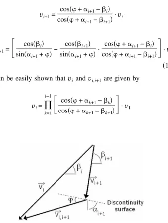
The work equation is written here for the general case of a multi-block failure mechanism and for a frictional and cohesive共,c兲 soil. This mechanism is a translational kinematically admissible failure mechanism. The different truncated rigid blocks involved in this mechanism move as rigid bodies. These blocks translate with velocities of different directions, which are collinear with the blocks axes and make an angle with the lateral discontinuity surfaces in order to respect the normality condition required by the limit analysis theory. The velocity of each block is determined by the condition that the relative velocity between the blocks in contact has the direction that makes an angle with the contact surface. The velocity hodograph is given in Fig. 10. The velocity
vi+1of block i + 1 and the interblock velocityvi,i+1between blocks i and i + 1 are determined from the velocity hodograph as follows:
vi+1=
cos共 + ␣i+1−i兲 cos共 + ␣i+1−i+1兲
·vi vi,i+1=
冋
cos共i兲 sin共␣i+1+兲 − cos共i+1兲 sin共␣i+1+兲 · cos共 + ␣i+1−i兲 cos共 + ␣i+1−i+1兲册
·vi 共13兲 It can be easily shown thatviandvi,i+1are given by
vi=
兿
k=1 i−1冋
cos共 + ␣k+1−k兲 cos共 + ␣k+1−k+1兲册
·v1 vi,i+1=兿
k=1 i−1冋
cos共k兲 sin共␣k+1+兲 − cos共k+1兲 sin共␣k+1+兲· cos共 + ␣k+1−k兲 cos共 + ␣k+1−k+1兲册
·v1 共14兲 Notice that the external forces involved in the present mechanism are the weights of the different truncated rigid blocks, the sur-charge loading acting on the ground surface, and the collapse pressure of the tunnel face. The rate of external work of the sur-charge loading should be calculated only in case of outcrop of the mechanism at the ground surface. The computation of the rate of external work of the different external forces is straightforward as follows:• Rate of work of the weight of the different truncated blocks
W˙␥=
冕冕
V冕
␥ ·vdV =兺
i=1 n ␥i·viVi=␥兺
i=1 n visin共i兲Vi 共15兲 • Rate of work of a possible uniform surcharge loading on theground surface
W˙
s=
冕冕
An
s·vdA⬘=sAn⬘sin共n兲vn 共16兲 • Rate of work of the collapse pressure of the tunnel face
W˙
c=
冕冕
A0
c·vdA = −cA0cos共1兲v1 共17兲 where Vi= volume of block i; An⬘= possible area of intersection of the last upper block with the ground surface 共if the mechanism outcrops兲; and A0= surface of the tunnel face.
Since no general plastic deformation of the truncated blocks is permitted to occur, the rate of internal energy dissipation takes place only along the different velocity discontinuity surfaces. These are 共1兲 the radial surfaces which are the contact areas be-tween adjacent truncated blocks; 共2兲 the lateral surfaces of the different truncated blocks. Notice that the rate of internal energy dissipation along a unit velocity discontinuity surface is equal to c ·␦u 共Chen 1975兲 where ␦u is the tangential component of the velocity along the velocity discontinuity surface. Calculation of the rate of internal energy dissipation along the different velocity discontinuity surfaces is straightforward. It is given by
D˙Ai,Si=
冕冕
S c ·v· cos共兲dS +冕冕
A c ·v· cos共兲dA = c · cos共兲 ·冉
兺
i=1 n viSi+兺
i=1 n−1 vi,i+1Ai,i+1冊
共18兲 where Si= lateral surface of block i and Ai,i+1= contact area be-tween blocks i and i + 1. Details on the computation of the vol-umes and surfaces are given in Appendix. The work equation consists in equating the rate of work of external forces to the rate of internal energy dissipation. It is given as follows:Fig. 9. Principle of generation of the second upper block
c · cos共兲 · 共
兺
i=1 n viSi+兺
i=1 n−1 vi,i+1Ai,i+1兲 = ␥兺
i=1 n visin共i兲Vi +sAn⬘sin共n兲vn−cA0cos共1兲v1 共19兲 After some simplifications, it is found that the tunnel collapse pressure is given byc=␥DN␥− cNc+sNs 共20兲 where N␥, Nc, and Nsare nondimensional coefficients. They rep-resent, respectively, the effect of soil weight, cohesion, and sur-charge loading. The expressions of the different coefficients N␥, Nc, and Nsare given as follows:
N␥=
兺
i=1 n冋
Vi A0D ·vi v1 · sin共i兲 cos共1兲册
共21兲 Nc=兺
i=1 n冋
Si A0 ·vi v1 · cos共兲 cos共1兲册
+兺
i=1 n−1冋
Ai,i+1 A0 ·vi,i+1 v1 · cos共兲 cos共1兲册
共22兲 Ns= An⬘ A0 ·vn v1 ·sin共n兲 cos共1兲 共23兲 In Eq. 共20兲, c depends not only on the physical, mechanical and geometrical characteristics␥, c, , and C/D, but also on the2n − 1 angular parameters␣k共k=2, ... ,n兲 and l共l=1, ... ,n兲. In the following sections, the critical tunnel collapse pressure is ob-tained by maximization of c given by Eq.共20兲 with respect to the␣k 共k=2, ... ,n兲 and l共l=1, ... ,n兲 angles.
Numerical Results
A computer program has been written in Matlab language to de-fine the different coefficients N␥, Nc, and Nsand the tunnel face collapse pressure c using Eqs. 共20兲–共23兲. The maximization of the collapse pressurecwith respect to the angular parameters of the failure mechanism was performed using the optimization tool implemented in Matlab. The number of subdivisions used for the generation of the collapse mechanism were n= 180 and nz= 200. These values are optimal and represent a good compromise be-tween results accuracy and computation time. The increase in the number of subdivisions with respect to the aforementioned values slightly improves the obtained results, the difference being smaller than 0.1%. The CPU time necessary for the computation of the critical collapse pressure was about 5–10 min on a 2.4 GHz quad-core CPU.
Influence of the Number of Blocks
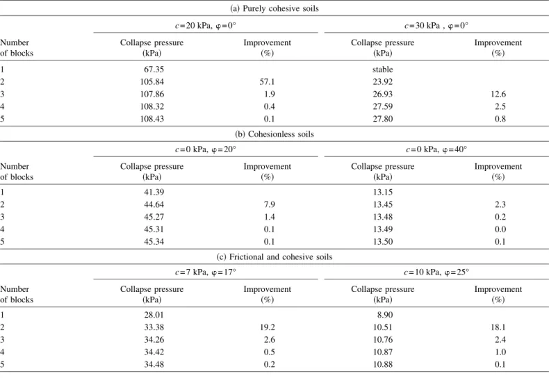
Table 1 gives the values of the critical collapse pressure c ob-tained from the maximization of the tunnel pressure with respect to the angular parameters of the failure mechanism for three
dif-Table 1. Influence of the Number of Blocks on the Critical Collapse Pressure:共a兲 Purely Cohesive Soils; 共b兲 Cohesionless soils; and 共c兲 Frictional and
Cohesive Soils
共a兲 Purely cohesive soils
Number of blocks
c = 20 kPa,=0° c = 30 kPa ,=0°
Collapse pressure
共kPa兲 Improvement共%兲 Collapse pressure共kPa兲 Improvement共%兲
1 67.35 stable 2 105.84 57.1 23.92 3 107.86 1.9 26.93 12.6 4 108.32 0.4 27.59 2.5 5 108.43 0.1 27.80 0.8 共b兲 Cohesionless soils Number of blocks c = 0 kPa,=20° c = 0 kPa,=40° Collapse pressure
共kPa兲 Improvement共%兲 Collapse pressure共kPa兲 Improvement共%兲
1 41.39 13.15
2 44.64 7.9 13.45 2.3
3 45.27 1.4 13.48 0.2
4 45.31 0.1 13.49 0.0
5 45.34 0.1 13.50 0.1
共c兲 Frictional and cohesive soils
Number of blocks
c = 7 kPa,=17° c = 10 kPa,=25°
Collapse pressure
共kPa兲 Improvement共%兲 Collapse pressure共kPa兲 Improvement共%兲
1 28.01 8.90
2 33.38 19.2 10.51 18.1
3 34.26 2.6 10.76 2.4
4 34.42 0.5 10.87 1.0
ferent types of soil:共1兲 a purely cohesive soil with cu= 20 and 30 kPa;共2兲 a cohesionless soil with =20° and 40° 共i.e., a loose and a dense sand, respectively兲; and 共3兲 a frictional and cohesive soil with c = 7 kPa and =17° 共i.e., a soft clay兲 and with c=10 kPa and=25° 共i.e., a stiff clay兲. The computation is made in the case where␥=18 kN/m3and C/D=1. The results are given for differ-ent numbers of the rigid blocks varying from one to five. This table also gives the percent increase 共i.e., improvement兲 in the collapse pressure with the increase in the number of blocks. The percent improvement corresponding to a given number n of blocks is computed with reference to the mechanism with n − 1 blocks. From Table 1, it can be seen that the increase共i.e., im-provement兲 in the collapse pressure decreases with the number of blocks increase and is smaller than 2.5% for n = 4. Therefore, in the following, the three-block mechanism will be used to obtain the collapse pressure for the different types of soil considered in the paper. This mechanism is defined by five angular parameters 共␣2, ␣3, 1, 2, and 3兲. Finally, it should be noticed that the one-block mechanism would be adequate only in the case of a cohesionless soil and for great values of the friction angle 共for example =40°兲. This is because the increase in the number of blocks slightly improves the solution in that case. Notice however that the improvement obtained by the use of a multiblock mecha-nism is significant for all the other cases; it is maximal in the case of a purely cohesive soil. For instance, when using two rigid blocks instead of one, an improvement of 57% was obtained in the case of a purely cohesive soil when cu= 20 kPa.
Analysis of the Face Stability by the Superposition Method
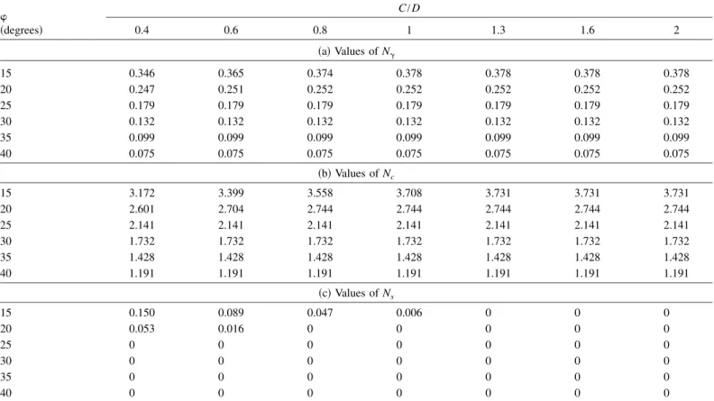
Table 2 provides the critical values of N␥, Nc, and Nsfor different values of C/D and as given by individual maximization of each
coefficient with respect to the five angular parameters of the fail-ure mechanism. The critical values of N␥, Nc, and Ns allow a quick calculation of the critical collapse pressure for practical purposes. This can be performed by simple application of Eq.共20兲 using the superposition principle. Notice that while the values of the critical coefficients N␥, Nc, and Nsand the critical collapse pressure c obtained by maximization are rigorous solutions in limit analysis, the collapse pressureccomputed using the super-position method is not a rigorous solution since it is approxi-mately calculated and it includes an error due to the superposition effect. In order to evaluate this error, Table 3 gives the values of the collapse pressures as obtained 共1兲 by direct maximization of this pressure;共2兲 by application of Eq. 共20兲 using the critical N␥, Nc, and Nscoefficients presented in Table 2, for the two cases of soft and stiff clays given before when C/D=1, and ␥ = 18 kN/m3. One can observe that the error is quite small共smaller than 0.5%兲 and is always conservative. From Table 2, one can observe that the values of Nc and Nsfound by numerical optimi-zation verify the following equation:
Nc= 1 − Ns
tan 共24兲
Table 2. Numerical Results for the Nondimensional Coefficients N␥, Nc, and Ns:共a兲 Values of N␥;共b兲 Values of Nc; and共c兲 Values of Ns
共degrees兲 C/D 0.4 0.6 0.8 1 1.3 1.6 2 共a兲 Values of N␥ 15 0.346 0.365 0.374 0.378 0.378 0.378 0.378 20 0.247 0.251 0.252 0.252 0.252 0.252 0.252 25 0.179 0.179 0.179 0.179 0.179 0.179 0.179 30 0.132 0.132 0.132 0.132 0.132 0.132 0.132 35 0.099 0.099 0.099 0.099 0.099 0.099 0.099 40 0.075 0.075 0.075 0.075 0.075 0.075 0.075 共b兲 Values of Nc 15 3.172 3.399 3.558 3.708 3.731 3.731 3.731 20 2.601 2.704 2.744 2.744 2.744 2.744 2.744 25 2.141 2.141 2.141 2.141 2.141 2.141 2.141 30 1.732 1.732 1.732 1.732 1.732 1.732 1.732 35 1.428 1.428 1.428 1.428 1.428 1.428 1.428 40 1.191 1.191 1.191 1.191 1.191 1.191 1.191 共c兲 Values of Ns 15 0.150 0.089 0.047 0.006 0 0 0 20 0.053 0.016 0 0 0 0 0 25 0 0 0 0 0 0 0 30 0 0 0 0 0 0 0 35 0 0 0 0 0 0 0 40 0 0 0 0 0 0 0
Table 3. Comparison of the Collapse Pressures as Given by the
Super-position Method and by Direct Optimization
Collapse pressure
Soft clay
共c=7 kPa,=17°兲 共c=10 kPa,=25°兲Stiff clay c共superposition兲 共kPa兲 34.38 10.81
This may be explained by the theorem of corresponding states 共Caquot 1934兲. Notice that this theorem allows one to compute the coefficient Nc using the coefficient Nsas can be easily seen from Eq.共24兲.
Collapse Pressures of a Purely Cohesive Soil
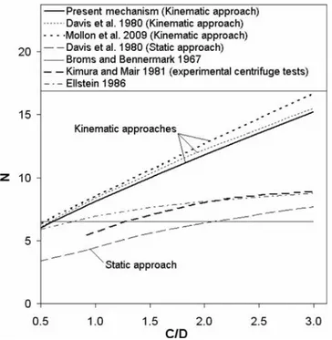
As mentioned in the introduction of this paper, the stability analy-sis of a tunnel face in the case of a purely cohesive soil is gov-erned by the load factor N. It should be remembered here that the load factor N at failure is N =共s+␥H−t兲/cu where t=c. Therefore, unlike the collapse pressure parametercfor which a greater value is searched to improve the best existing solutions, one should obtain a smaller value of the parameter N to improve the best solutions of this parameter. From the computed values of the critical collapse pressuresc, the present critical load factors corresponding to the failure state共i.e., t=c兲 were plotted versus C/D in Fig. 11. The N values may also be obtained by an alter-native and equivalent method by minimizing the N parameter given earlier with respect to the angular parameters of the failure mechanism. The critical values of N calculated based on the model by Mollon et al. 共2009兲 and those given by Broms and Bennermark共1967兲, Davis et al. 共1980兲, Kimura and Mair 共1981兲, and Ellstein共1986兲 are also given in this figure. Notice that Fig. 11 may be used to check the stability of the tunnel face in a purely cohesive soil in two different ways. Stability is ensured as long as N computed using the applied tunnel pressuretis smaller than the critical value of N deduced from Fig. 11. This check may also be performed by computing the collapse pressure c from the critical N value of Fig. 11 and comparing this pressure to the applied one共i.e., t兲.
From Fig. 11, it appears that the present critical values of N are smaller共i.e., better兲 than the available solutions by Mollon et al. 共2009兲 and Davis et al. 共1980兲 using a kinematical approach. The improvement is equal to 8% with respect to the results by Mollon et al.共2009兲 and to 3.5% with respect to the results by Davis et al.
共1980兲 in the case where C/D=2.5. Finally, it appears that a significant scatter exists between the solutions given by the kine-matic and static approaches by Davis et al.共1980兲. This may be explained by the simplified stress field used in the static approach of limit analysis. The centrifuge results by Kimura and Mair 共1981兲 and the results by Ellstein 共1986兲 show significant differ-ences with the present solutions. The scatter attains 40% when C/D=2. This means that the case of a purely cohesive soil re-quires further investigations.
Collapse Pressures of a Cohesionless Soil
The solutions of the critical tunnel face pressure as determined by Leca and Dormieux 共1990兲, Mollon et al. 共2009兲, and by the present approach are given in Fig. 12 for two cases of a cohesion-less soil:=20° and 40°. It should be remembered here that all these results are based on the kinematical approach of limit analy-sis. One can see that the improvement共i.e., increase of the col-lapse pressure兲 of the present solution attains 12% with respect to the one by Mollon et al.共2009兲 and 19% with respect to that by Leca and Dormieux 共1990兲 when =20° and C/D⬎0.5. This figure also shows that in the common range of variation of 共=20–40°兲, the parameter C/D has no influence on the collapse pressures when C/D is higher than 0.5 共this geometrical condition is always true in practice兲. This is because the critical failure mechanism obtained from the maximization process is a nonout-cropping mechanism for these cases and it does not change with the increase of C/D.
Fig. 13 presents a comparison between the collapse pressures given by the proposed mechanism and those given by Anagnostou and Kovari共1996兲 using a limit equilibrium method, Eisenstein and Ezzeldine共1994兲 using a numerical approach, and Leca and Dormieux共1990兲 using kinematic and static approaches in limit analysis. Again, one can observe that the solutions obtained by Leca and Dormieux 共1990兲 using the static approach in limit analysis are quite far from the results given by the other methods. This is because of the simplified stress field used by Leca and Dormieux共1990兲. The present results improve the solutions given
Fig. 11. Comparison of present load factor N of a purely cohesive
soil with that of other writers
Fig. 12. Comparison of present solutions ofcwith those of other
by Leca and Dormieux共1990兲 using a kinematic approach and are between the results given by Eisenstein and Ezzeldine共1994兲 and Anagnostou and Kovari共1996兲.
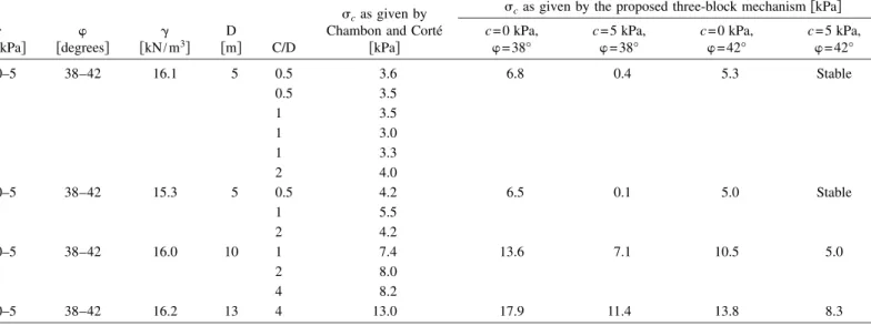
Table 4 presents the collapse pressures obtained by Chambon and Corté 共1994兲 from centrifuge tests in Nantes LCPC using sand. The ranges of shear strength characteristics given by Chambon and Corté 共1994兲 are as follows: =38–42°, and c = 0 – 5 kPa. As can be seen, these values of the shear strength parameters show that the soil exhibits a small nonnull cohesion for the sand. Chambon and Corté共1994兲 explained this phenom-enon by some uncertainty in the measurements of internal friction angle and cohesion obtained from the shear box. Notice that the
centrifuge tests were realized for several values of D, C/D, and ␥. Table 4 also presents the corresponding collapse pressures as given by the proposed three-block mechanism, for the four com-binations of extreme values of c and suggested by Chambon and Corté 共1994兲. In this table, a unique value of the calculated pressure is given for several values of C/D because of the high values of proposed by Chambon and Corté 共the mechanism never outcrops in these cases兲. As one can see, the results ob-tained by centrifuge tests are within the large range of values of the tunnel pressures computed based on the three-block mecha-nism using the different values of the soil shear strength param-eters. The wide range of values of the shear strength parameters given by Chambon and Corté 共1989兲 does not allow a fair and accurate comparison with the experimental collapse pressures. Collapse Pressures of a Frictional and Cohesive Soil Fig. 14 presents the solutions of the collapse pressure as given by Leca and Dormieux 共1990兲, Mollon et al. 共2009兲, and by
Fig. 13. Comparison of present solutions ofcwith those of other
writers in the case of a cohesionless soil
Table 4. Comparison between Experimental and Computed Collapse Pressures
c
关kPa兴 关degrees兴 关kN/m␥ 3兴
D
关m兴 C/D
cas given by
Chambon and Corté 关kPa兴
cas given by the proposed three-block mechanism关kPa兴
c = 0 kPa,
=38° c = 5 kPa,=38° c = 0 kPa,=42° c = 5 kPa,=42°
0–5 38–42 16.1 5 0.5 3.6 6.8 0.4 5.3 Stable 0.5 3.5 1 3.5 1 3.0 1 3.3 2 4.0 0–5 38–42 15.3 5 0.5 4.2 6.5 0.1 5.0 Stable 1 5.5 2 4.2 0–5 38–42 16.0 10 1 7.4 13.6 7.1 10.5 5.0 2 8.0 4 8.2 0–5 38–42 16.2 13 4 13.0 17.9 11.4 13.8 8.3
Fig. 14. Comparison of present solutions ofcwith those of other
the present approach for two soil configurations: c = 7 kPa and =17° 共soft clay兲, and c=10 kPa and =25° 共stiff clay兲. All these results are based on the kinematical approach of limit analy-sis. For C/D⬎0.8, the improvement of the present solution with respect to the one by Leca and Dormieux共1990兲 and Mollon et al. 共2009兲 is about 44% and 20%, respectively, for the soft clay, and attains 89% and 40%, respectively, for the stiff clay. For the C/D values higher than 0.8共which is almost always true in practice兲, the values of the collapse pressures remain constant. Again, this phenomenon may be explained by the fact that the critical failure mechanism obtained from optimization does not outcrop at the ground surface for these cases.
Critical Collapse Mechanisms
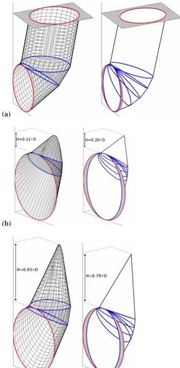
Fig. 15 shows a comparison between the critical failure mecha-nisms given by Mollon et al.共2009兲 and by the present approach in three different cases: 共1兲 a purely cohesive soil with cu = 20 kPa and C/D=1; 共2兲 a cohesionless soil with =30° and C/D⬎0.5 共case of a nonoutcropping mechanism兲; and 共3兲 a soft clay with=17°, c=7 kPa, and C/D⬎1. For both approaches, the failure mechanism outcrops in the case of a purely cohesive soil as expected. It means that for this type of soil, the parameter C/D is of major importance. This is not true for a cohesionless or a frictional and cohesive soil with high to moderate friction angle 共=20–40°兲 since the critical tunnel pressure is independent of the tunnel cover in these cases. From Fig. 15, one can also see that the critical failure mechanisms given by both approaches are quite similar. Notice however that the prior mechanism by Mollon et al.共2009兲 does not intersect the whole tunnel face; the grey part of the tunnel face being at rest in the mechanism by Mollon et al. 共2009兲 共cf., Fig. 15兲. This incompatibility of the mechanism with the tunnel cross section was removed in the method proposed herein. Notice also that the upper block of the present mechanism does not exhibit a unique apex as would appear from Fig. 15. Instead, a curved line was obtained at the top of this block as may be easily seen from Fig. 16. It should be emphasized here that for a small value of the friction angle, the curved line developed at the top of the upper block has a very limited length共not shown in this paper兲. Thus, the upper block approaches 共but is not兲 a regu-lar cone in this case; the lines developed along the j index共for a given i兲 are approximately close to 共but are not兲 straight lines. In this case, the last upper block terminates with a somewhat unique apex. Notice however that for greater values of the friction angle, the upper block is far from a regular cone as was shown in Fig. 16 for=30°.
Design Chart
Fig. 17 depicts a design chart that may be used in practice to determine the critical collapse pressure of a circular tunnel face in the case of a frictional and cohesive soil. This chart allows one to evaluate the nondimensional collapse pressure c/␥D for different values of c/␥D and for various values of 共running from 15° to 40°兲 when C/D⬎0.8 共the condition C/D⬎0.8 is almost always true in practice兲. Notice that the range C/D⬎0.8 was chosen because the critical failure mechanism would be a nonoutcropping mechanism in this case for all the range of values of the soil parameters considered in the paper and this renders the chart independent of C/D. Notice finally that this chart may also be used for the computation of the required tunnel face pressure for which a prescribed safety factor Fsdefined with respect to the soil shear strength parameters c and tan is
de-sired. This may be achieved if one uses the chart withdand cdin lieu of and c where d and cd are based on the following equations: cd= c Fs 共25兲 d= arctan
冉
tan Fs冊
共26兲 (a) (b) (c)Fig. 15. Comparison of the failure mechanisms as given by the
present approach 共left兲 and by Mollon et al. 共2009兲 共after Mollon et al. 2009兲 共right兲: 共a兲 =0° and cu= 20 kPa; 共b兲 =30° and
Conclusions
A new multiblock translational failure mechanism based on the kinematical approach of limit analysis theory was presented in this paper in the aim to improve the existing solutions of the critical collapse pressure of a shallow circular tunnel driven by a pressurized shield. The present failure mechanism has a signifi-cant advantage with respect to the existing limit analysis mecha-nisms by Leca and Dormieux 共1990兲 and Mollon et al. 共2009兲 since it takes into account the entire circular tunnel face and not only an inscribed ellipse to this circular area. This was made possible by the use of a spatial discretization technique allowing one to generate the three-dimensional failure surface point by point. The three-dimensional failure surface was determined by defining the contours of this surface at several vertical planes parallel to the tunnel face. This failure mechanism respects the normality condition required by limit analysis since the three-dimensional failure surface so generated is constructed in such a manner that the velocity vector makes an angle with the veloc-ity discontinuveloc-ity surfaces anywhere along these surfaces. Al-though the three-dimensional geometrical construction presented in this paper is applied to a circular tunnel face, it may be easily applied to any form of the tunnel face for the stability analysis of a tunnel driven by the classical methods. The numerical results have shown that:
• A one-block mechanism would be adequate only in the case of a cohesionless soil and for great values of the friction angle 共for example =40°兲. This is because the increase in the num-ber of blocks slightly improves the solution in that case. No-tice however that the improvement obtained by the use of a multiblock mechanism is significant for all the other cases; it is maximal in the case of a purely cohesive soil. Finally, it was found that the use of a three-block mechanism gives accurate results for all the types of soils studied in the paper共frictional and/or cohesive兲 with a reasonable computation time of about 5–10 min.
• The critical values of N␥, Nc, and Nsare given in the paper for the computation of the tunnel collapse pressure using the su-perposition method. It was shown that the error induced by the superposition principle is quite small共smaller than 0.5%兲 and is always conservative. Notice however that the collapse pres-sures computed based on the superposition principle can not be considered as rigorous solutions in the framework of limit analysis theory.
• The proposed failure mechanism improves the available solu-tions of the load factor N and the collapse pressurec. In the case of purely cohesive soils, the improvement共i.e., decrease兲 of the critical value of N with respect to the one by Mollon et al.共2009兲 is equal to 8% for C/D=2.5. For cohesionless soils, the improvement 共i.e., increase兲 of the critical collapse pres-surecwith respect to the one given by Mollon et al.共2009兲 is equal to 12% when=20°. This improvement can attain more than 40% for stiff clays. The comparison with other theoretical and experimental approaches has shown that a good agreement with other writers’ results was obtained in the case of a cohe-sionless soil. However, significant differences exist with cen-trifuge tests in the case of a purely cohesive soil. These differences require further investigation.
• The failure mechanism always outcrops in the case of a purely cohesive soil as expected. It means that in this case the param-eter C/D is of major importance. This is not the case for a cohesionless or a frictional and cohesive soil with high to moderate friction angle =20–40° since the critical tunnel pressure is independent of the tunnel cover in these cases. • A design chart was proposed, allowing one to evaluate the
critical collapse pressure for a frictional and cohesive soil. This chart may also be used for the computation of the re-quired tunnel face pressure for which a prescribed safety factor Fsdefined with respect to the soil shear strength parameters c and tan is desired.
Finally, it should be mentioned that the failure mechanism
Fig. 16. Shape of the curved line at the top of the upper block of the failure mechanism when=30°
Fig. 17. Design chart of the critical collapse pressure for a frictional
presented in this paper may be extended to the blow-out case of failure corresponding to the passive state in the soil in front of the tunnel face. This mechanism permits to compute the blow-out face pressures. In this case, the velocities are acting upwards and the failure mechanism always outcrops on the ground surface. Although this state of failure is not realistic in the case of a frictional and cohesive soil, it would be of some interest in the case of a soft clay.
Appendix. Volumes and Surfaces Calculation
The calculation of the volume and lateral surface of a given block is performed by a simple summation of elementary volumes and lateral surfaces Vi,jand Si,jassociated with the different element areas of the failure surface of this block. This may be explained as follows. For a given element area of the failure surface bounded by four points 共Pi,j, Pi+1,j, Pi,j+1, and Pi+1,j+1兲, let 共Pi,j⬘, Pi+1,j⬘ , Pi,j+1⬘ , and Pi+1,j+1⬘ 兲 be the projections of these four points on the plane x = 0 as shown in Fig. 18. This quadrilateral element area may be subdivided into two triangular facets by two different ways: 关共Pi,j; Pi+1,j; Pi,j+1兲 and 共Pi+1,j; Pi,j+1; Pi+1,j+1兲兴 or 关共Pi,j; Pi,j+1; Pi+1,j+1兲 and 共Pi,j; Pi+1,j; Pi+1,j+1兲兴. Those four triangular facets are denoted a, b, c, and d as shown in Fig. 18. In the same manner, the volume bounded by the four points共Pi,j, Pi+1,j, Pi,j+1, Pi+1,j+1兲 and their projection on the plane x=0, may be computed by defining four volumes Va, Vb, Vc, and Vd, each one being bounded by the corresponding triangular facet共a, b, c, or d兲 and its projection on the plane x = 0. For example, the volume Va is bounded by the six points共Pi,j; Pi+1,j; Pi,j+1; Pi,j⬘; Pi+1,j⬘ ; Pi,j+1⬘ 兲 as shown in Fig. 18. For each one of the triangular facets, it is very easy to determine the surface and the corresponding volume 共which is equal to the projected surface of this triangle on the plane x = 0 multiplied by the distance from the barycenter of the triangular facet to the projection plane x = 0兲 using the coordinates of the three points of the triangle. The surface共respectively vol-ume兲 of the four-points element is approximated here as the mean value between the surfaces共respectively, volumes兲 obtained from the two ways of subdividing the quadrilateral surface into two triangles, i.e. Si,j= 共Sa+ Sb兲 + 共Sc+ Sd兲 2 Vi,j= 共Va+ Vb兲 + 共Vc+ Vd兲 2 共27兲
Concerning the calculation of the interblock surfaces and of the outcropping surface, this was performed using the classical trapezoidal method.
References
Anagnostou, G., and Kovari, K.共1996兲. “Face stability conditions with earth-pressure-balanced shields.” Tunn. Undergr. Space Technol.,
11共2兲, 165–173.
Augarde, C. E., Lyamin, A. V., and Sloan, S. W.共2003兲. “Stability of an undrained plane strain heading revisited.” Comput. Geotech., 30, 419–430.
Broere, W.共1998兲. “Face stability calculation for a slurry shield in het-erogeneous soft soils.” Proc., World Tunnel Congress 98 on Tunnels
and Metropolises, Vol. 1, Balkema, Rotterdam, The Netherlands, 215–
218.
Broms, B. B., and Bennermark, H.共1967兲. “Stability of clay at vertical openings.” Soil Mech. Found. Eng. (Engl. Transl.), 193共SM1兲, 71–94. Caquot, A. I.共1934兲. Equilibre des massifs à frottement interne—Stabilité
des terres pulvérulents et cohérents, Gauthier-Villars, Paris 共in
French兲.
Chambon, P., and Corté, J. F.共1994兲. “Shallow tunnels in cohesionless soil: Stability of tunnel face.” J. Geotech. Eng., 120共7兲, 1148–1165. Chen, W. F.共1975兲. Limit analysis and soil plasticity, Elsevier Science,
Amsterdam, The Netherlands.
Davis, E. H., Gunn, M. J., Mair, R. J., and Seneviratne, H. N.共1980兲. “The stability of shallow tunnels and underground openings in cohe-sive material.” Geotechnique, 30共4兲, 397–416.
Eisenstein, A. R., and Ezzeldine, O.共1994兲. “The role of face pressure for shields with positive ground control.” Tunneling and ground
condi-tions, Balkema, Rotterdam, The Netherlands, 557–571.
Ellstein, A.R. 共1986兲. “Heading failure of lined tunnels in soft soils.”
Tunnels and tunnelling, 18, 51–54.
Horn, N.共1961兲. “Horizontaler erddruck auf senkrechte abschlussflächen von tunnelröhren.” Landeskonferenz der ungarischen tiefbauindustrie, Landeskonferenz der Ungarischen Tiefbauindustrie, Budapest, Hun-gary, 7–16.
Kimura, T., and Mair, R. J.共1981兲. “Centrifugal testing of model tunnels in clay.” Proc., 10th Int. Conf. of Soil Mechanics and Foundation
Engineering, Vol. 1, Balkema, Rotterdam, The Netherlands, 319–322.
Klar, A., Osman, A. S., and Bolton, M.共2007兲. “2D and 3D upper bound solutions for tunnel excavation using ‘elastic’ flow fields.” Int. J.
Numer. Analyt. Meth. Geomech., 31共12兲, 1367–1374.
Leca, E., and Dormieux, L.共1990兲. “Upper and lower bound solutions for the face stability of shallow circular tunnels in frictional material.”
Geotechnique, 40共4兲, 581–606.
Mair, R. J.共1979兲. “Centrifugal modelling of tunnel construction in soft clay.” Ph.D. thesis, Univ. of Cambridge, Cambridge, U.K.
Michalowski, R. L.共1997兲. “An estimate of the influence of soil weight on bearing capacity using limit analysis.” Soils Found., 37共4兲, 57–64. Michalowski, R. L.共2001兲. “Upper-bound load estimates on square and
rectangular footings.” Geotechnique, 51共9兲, 787–798.
Mollon, G., Dias, D., and Soubra, A.-H.共2009兲. “Probabilistic analysis and design of circular tunnels against face stability.” Int. J. Geomech.,
9共6兲, 237–249.
Oberlé, S.共1996兲. “Application de la méthode cinématique à l’étude de la
stabilité d’un front de taille de tunnel.” Final project, ENSAIS, France 共in French兲.
Osman, A. S., Mair, R. J., and Bolton, M. D.共2006兲. “On the kinematics of 2D tunnel collapse in undrained clay.” Geotechnique, 56共9兲, 585– 595.
Sagaseta, C. 共1987兲. “Analysis of undrained soil deformation due to ground loss.” Geotechnique, 37共3兲, 301–320.
Soubra, A.-H. 共1999兲. “Upper-bound solutions for bearing capacity of foundations.” J. Geotech. Geoenviron. Eng., 125共1兲, 59–68. Soubra, A.-H., and Regenass, P.共2000兲. “Three-dimensional passive earth
pressures by kinematical approach.” J. Geotech. Geoenviron. Eng., 126共11兲, 969–978.
Takano, D., Otani, J., Nagatani, H., and Mukunoki, T.共2006兲. “Applica-tion of X-ray CT boundary value problems in geotechnical engineering—Research on tunnel face failure.” Proc., Geocongress
2006, ASCE, Reston, Va.
Verruijt, A., and Booker, J. R.共1996兲. “Surface settlements due to defor-mation of a tunnel in an elastic half plane.” Geotechnique, 46共4兲, 753–756.