HAL Id: hal-01666706
https://hal.archives-ouvertes.fr/hal-01666706
Submitted on 13 Dec 2018
HAL is a multi-disciplinary open access
archive for the deposit and dissemination of
sci-entific research documents, whether they are
pub-lished or not. The documents may come from
teaching and research institutions in France or
abroad, or from public or private research centers.
L’archive ouverte pluridisciplinaire HAL, est
destinée au dépôt et à la diffusion de documents
scientifiques de niveau recherche, publiés ou non,
émanant des établissements d’enseignement et de
recherche français ou étrangers, des laboratoires
publics ou privés.
A wear model based on cumulative cyclic plastic
straining
Christine Boher, Olivier Barrau, R. Gras, Farhad Rezai-Aria
To cite this version:
Christine Boher, Olivier Barrau, R. Gras, Farhad Rezai-Aria. A wear model based on cumulative
cyclic plastic straining. Wear, Elsevier, 2009, 267 (5-8), pp.1087-1094. �10.1016/j.wear.2009.01.010�.
�hal-01666706�
A wear model based on cumulative cyclic plastic straining
C. Boher
a,∗, O. Barrau
a,1, R. Gras
b, F. Rezai-Aria
aaToulouse University, Ecole Mines Albi, CROMeP, F-81013 Albi cedex, France bSupméca, 3 rue F. Hainaut, 93000 Saint-Ouen, France
Keywords: Wear model Plastic deformation Ratchetting effect Tool steel LCF
a b s t r a c t
Given the specific micro-structure of some steel grades, under tribological conditions the sub-surface material or sub-layers of sliding bodies are prone to cumulative cyclic plastic deformation, leading to the formation and emission of wear debris.
In the present paper, a new wear model based on a cyclic ratchetting-type plastic deformation of sub-surface material is proposed. It is considered that the debris is formed and the wear-loss occurs when the accumulated plastic deformation at sub-surface exceeds “a critical strain” or “rupture limit”. The model takes into account the number of cycles or test duration, a characteristic thickness of the sub-layer dependent on tribological conditions and material properties, the shear rupture ductility and an average plastic strain increment. The average plastic strain increment is estimated by numerical simulation of pin-on-disc friction. A very close correlation is found between the predicted and experimental wear heights versus time and/or versus the number of cycles.
The wear investigations were carried out on a high-temperature pin-on-disc tribometer under dry friction conditions. Experiments were performed under constant load, speed and disc temperature for different durations. The steel grade involved was a tempered martensitic tool steel X38CrMoV5 (AISI H11). Wear mechanisms were investigated by Scanning Electron Microscopy (SEM) observations in surface and cross-section.
1. Introduction
Hot metal forging tools used in processes such as forging, rolling or metal sheet forming, are subjected to transient thermal and mechanical loadings. Under these conditions, the contact surfaces of the tools are damaged by complex interactions between wear and thermal fatigue. In addition, the wear and thermal fatigue that are subjected to is coupled with oxidation. It is well known that the wear mechanisms of two bodies in relative movement depend on various parameters and conditions acting conjointly. The loading conditions (stress and speed) the surface and interface proper-ties (dryness, lubrication, oxidation and asperiproper-ties), the material behaviour (static and cyclic plastic behaviour) and the mechan-ical properties (flow stress and/or hardness, fatigue and rupture properties) are among the parameters required to investigate the quantitative evaluation of wear.
One of the characterization difficulties encountered here is that surfaces and sub-surfaces cannot be considered as simple labo-ratory specimens, where stresses and strains are straightforward, but rather as samples subjected to thermo-mechanical loading
∗ Corresponding author. Tel.: +33 5 63 49 31 69; fax: +33 5 63 49 32 42.
E-mail address:[email protected](C. Boher).
1Now with Aurock, 54 rue Gustave Eiffel, 81000 Albi, France.
gradients and micro-structural modifications (Mechanical Mixed Layers for example), requiring appropriate simulations and thermo-mechanical analysis.
Knowledge of the local stress and strain distributions in the con-tact region is a key requirement to gain a better insight into the wear mechanisms and thus achieve an appropriate modelling of the wear. The changes in the contact features (e.g. asperity and sub-surface aspects) during the wear process constitute an addi-tional difficulty since the boundary conditions are continuously evolving. Friction evolves during wear, mainly because of the evo-lution of the contact geometry and also because of the formation and circulation of debris. These complex and combined parameters make wear prediction difficult, in particular where a microscopic or “local” approach to friction and wear is concerned. The coupling effects of material properties and loadings need to be addressed.
Models may be found in the literature dealing with differ-ent tribological fields and wear mechanisms [1]. In many cases these are macroscopic and phenomenological approaches aiming to describe the microscopic wear mechanisms occurring at the contact regions. Archard’s wear law is one of these well-known quantitative macroscopic models[2]. This law and its modified versions[3–6], introduce a parameter K that is experimental conditions dependent and therefore needs to be adjusted or estimated for each applica-tion, in particular when the industrial applications, such as forming tools, are of concern.
Other authors have found a considerable amount of microscopic evidence revealing that the surface layer close to the “friction sur-face”, in particular in ductile materials, may be subjected to large plastic shearing under sliding. To develop wear models, several authors have used the plastic deformation concept of the surface and the gradient of plastic deformation inwards from the surface [7–18].
In delamination theory, the plastic deformation of the more duc-tile body is caused by the asperities of the harder body and induces a cyclic plastic shear strain that accumulates with repeated cycles. A further important characteristic, even in sliding friction, involves non-proportional back and forth loading conditions and hydrostatic pressure[19].
The loading undergone by the counterparts in cyclic stressing is similar to that encountered in fatigue loading, but differs in several ways[14]. Firstly, the major deformation mode in friction corre-sponds to shear[12]. In friction, the shear strain can be much higher than the uni-axial tension ductility, whereas the deformation in compression (due to normal forces in tribological tests) is much lower, with strains of only 1–2%. Secondly, the loading under friction leads neither to constant deformation amplitude nor to constant stress amplitude. Moreover, an asymmetric loading in fatigue mode favours the ratchetting effect.
Furthermore, high hydrostatic pressure may increase ductility by eliminating or retarding the initiation and growth rate of damage [20,21]. The friction shear could be compared to torsion strain. So, it could be considered that the hydrostatic pressure could increase ductility and deformation accumulation before rupture by shearing. Kapoor et al. have studied and are working on the ratchet-ting concept through a ratchetratchet-ting failure-based approach to wear modelling, where ratchetting failure occurs when the accumulated deformation exceeds a critical value[11,16–18].
This contribution deals with a wear model based on sub-surface cyclic ratchetting plastic strain accumulations as the basic process of debris formation and rupture. It is considered that the debris is formed when the cumulative plastic deformation in sub-surface layers achieves a critical limit that is governed by the “ductile rup-ture property” of the material.
Based on experimental observations and detailed microscopic examinations, a material-dependent parameter is introduced to describe the physical wear mechanism that is observed. The model is assessed on a tempered martensitic tool steel, X38CrMoV5-AISI H11, examined on a high-temperature pin-on-disc tribological facil-ity, used in hot metal forming.
In this investigation, attention is only focused on the role of the cyclic plastic strain of the hard material (X38CrMoV5, AISI H11) used as a pin. The role of the cyclic plastic strain behaviour of the more ductile steel (XC18-AISI 1018), used as a disc, is not addressed in this paper. In addition, in order to better disconnect the complex effects and interactions of a high-temperature friction test, it was decided to assess the friction and wear in the specific conditions of a steady-state temperature.
2. Experiments and materials
2.1. High-temperature pin-on-disc tribometer
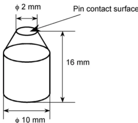
The investigations were carried out on a high-temperature pin-on-disc tribometer under dry friction conditions. A detailed description of this tribometer is given in[22,23]. The disc is a cylin-der of 30 mm diameter and the pin has a cylindrical shape (diameter 10 mm) with a truncated conic end with a flat circular surface of 2 mm diameter (surface contact) (Fig. 1).
The disc was heated by a high-frequency induction CELES facil-ity (3 kW). The disc surface temperature was controlled by a
Fig. 1. Schema of the pin geometry (the conic angle is 45◦).
bi-chromatic infrared pyrometer. First the disc was heated to a pre-scribed temperature while the pin was kept out of contact at room temperature. After stabilisation of the disc temperature, the pin was put in contact with the hot disc and the friction test started immediately. The initial contact between the pin and the disc was thus a contact between metal (pin) and iron oxide (disc). The pin temperature increased in several heat exchanges: thermal conduc-tion, radiaconduc-tion, convecconduc-tion, and also generated friction heat (a weak influence). Tribological tests were performed under a normal load of 20 N with a disc rotation speed of 100 rpm (0.13 m/s). The effect of temperature from RT to 950◦C on the friction coefficient evolution and pin wear has been reported elsewhere[24,25]. The attention of this paper is focused on the results of the experiments performed at 700◦C with different test durations (120, 300, 600, 900 and 3600 s of friction) to measure the wear-loss of the pin. It is interesting to note, however, that the surface temperature of the pin increased from RT to 700◦C after about 5 min. Each test was carried out at least twice to assess the reproducibility of the experiments.
Pin surface and cross-section examinations (parallel to the fric-tion direcfric-tion) were performed with SEM and ESEM to get a better insight into the micro-structural changes in the sub-surface.
2.2. Materials
The pins are machined in 5% chromium double-tempered martensitic steel grade bars (X38CrMoV5, AISI H11) with an initial hardness of 47 HRC, delivered free of charge by Aubert&Duval. Discs are ferrito-pearlitic mild steels (XC18, AISI 1018). The X38CrMoV5 steel is widely used for forging dies, whereas AISI 1018 mild steel is used in forged condition in the automotive industry. The initial hardness of AISI 1018 is about 168HV. The chemical compositions of the two steels are reported inTable 1.
The X38CrMoV5 (AISI H11) steel micro-structure is constituted by randomly oriented lathes. The lath dimensions are about 2 !m in thickness and 15 !m in length (Fig. 2). This micro-structure has a very high density of tangled dislocations and also a large amount of small carbides, which provide a good strength to the steel at room and high temperatures[26].
2.2.1. Mechanical cyclic behaviour of X38CrMoV5 (AISI H11)
X38CrMoV5 (AISI H11) is prone to thermal[29]and mechani-cal softening[27,28]. Jean et al.[29]have reported the softening of this steel under several isothermal[27,28]and thermal fatigue conditions. The thermo-mechanical fatigue softening is reported in [30]. Detailed Low Cycle Fatigue (LCF) investigations under isother-mal and non-isotherisother-mal conditions have revealed that X38CrMoV5 tool steel invariably presents a high degree of continuous soften-ing from the early cycles, even at room temperature. The softensoften-ing is due to the carbides coarsening and dislocation annihilations
Table 1
Chemical composition of two steels (wt.%).
Element C Cr Mn V Ni Mo Si Fe
Pin AISI H11 0.4 5.05 0.49 0.47 0.2 1.25 0.92 Bal.
Disc AISI 1018 0.18 <0.4 0.4–0.7 – <0.4 <0.1 0.15–0.35 Bal.
Fig. 2. Tempered martensitic micro-structure of the X38CrMoV5-AISI H11 steel grade.
[26]. In general, the first softening stage is followed by a second linear softening stage, before a rapid decrease of stress due to final crack propagation and rupture of the specimens[27–30]. Up to 550◦C the fatigue softening rate is “slow” but then increases greatly beyond this temperature[27]. Daffos et al.[28]have shown that fatigue softening is also strain rate dependent and that by lowering the strain rate, the softening increases and its effect becomes very significant when the temperature is higher than 550◦C. Under stress-controlled cyclic experiments, an important progressive and cumulative plastic strain (ratchetting) is observed [31]. The accommodation rate depends on the test temperature and the stress range amplitude.Fig. 3shows an example of such behaviour at 300 and 500◦C. At each temperature, the load is increased[31].
2.2.2. Tensile and torsion ductilities of X38CrMoV5 (AISI H11)
High-temperature rupture ductility under tension (εc) and torsion ("c ) of X38CrMoV5 steel (47 HRC) were determined respectively at the “Ecole des Mines d’Albi” and the Aubert&Duval laboratory (Table 2). While the wear experiments were performed
Fig. 3. Stress-controlled experiments performed at 300◦C (left), 500◦C (right)
(ini-tial total strain #ε = ±0.8%)[31].
Table 2
Comparison of strain to rupture in tension and torsion experiments at high temperature.
Experiment Temperature (◦C) Rupture ductility (%)
Tensile 700 εc= 16%
Torsion 640 "c= 724%
Fig. 4. Variation of the friction coefficient as a function of friction durations at 700◦C
under 20 N normal load.
at 700◦C, because of technical difficulties, the torsion ductility was
measured at a slightly lower temperature (640◦C). As was expected,
the high-temperature rupture ductility in tension was very much lower than in torsion (Table 2).
3. Results and discussion
3.1. Friction experiments
Fig. 4presents the evolution of the measured friction coefficients for different test durations (120, 300, 600, 900 and 3600 s) versus time. A good reproducibility of the friction tests is shown and the coefficients of friction are very close (Table 3) with a constant mean standard deviation of about ±0.02. A steady-state regime of the friction coefficient is reached rapidly (120 s) .
3.2. Pin surface damage mechanism
The surface and cross-section of pins were examined post-mortem by SEM or ESEM. The surfaces of the flat pins show no-or very minno-or-transferred-wear particles. Wear debris agglomer-ation in the entrance of the contact zone is not observed; this indicates that the amount of debris particles is not sufficient to cover the contact surface and to form a protective layer. In addi-tion, the transferred oxidized particles (iron oxides) do not develop
Table 3
Friction coefficient as a function of test duration.
Test duration (s) Friction coefficient
120 0.45
300 0.46
600 0.44
900 0.48
Fig. 5. SEM flat pin wear surface observations (20 N–700◦C–3600 s) (sliding direction right to left).
glazed protective layers. Surface scratches (or grooves) are also observed in the contact zone (Fig. 5a). Parallel, juxtaposed “stripes” with alternately oxide-dominant and metallic-dominant scars are observed (Fig. 5b). Whatever the test duration, the contact surfaces of the flat pins present similar features, presumably indicating the same wear mechanism in steady-state wear regimes (the constant friction coefficient regime). Based on detailed surface and cross-section examinations of flat pins[32], it was concluded that the cumulative plastic deformation is the main mechanism for abra-sion wear in the steady-state regimes of X38CrMoV5 AISI H11 steel.
3.3. Sub-surface wear damage mechanism
The SEM and ESEM examinations were carried out on cross-sections parallel to the friction direction to gain a better insight into the micro-structural evolutions.
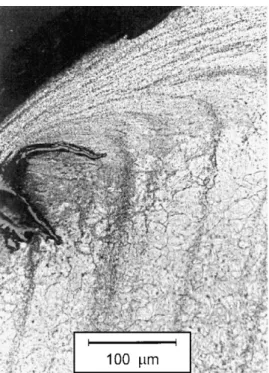
In all tests conditions, very drastically elongated tempered martensitic laths were always formed along the sliding direc-tion on the whole sub-surface of the wear contact zone of the pins. Detailed observations revealed that a highly compact laminar “multilayer”-type elongated lath is formed (Fig. 6). This micro-structural evolution transforms a randomly orientated lath into a well-paralleled (textured structure), regular and uniform micro-structure beneath the pin surface along the contact zone. Such micro-structural feature evolutions (e.g. lath elongation, orienta-tion,) are also observed in industrials tools (Fig. 7). They could be attributed to the lack of necking, that changes stress state from plane stress to plane strain in tensile test, providing the tempered martensitic laths the capability to undergo very highly plastic shear straining, resembling a “super-plastic” capability. The diminution
Fig. 6. Tempered martensitic laths, elongated and highly deformed by plastic shear
staining on the pin sub-surface after 1 h of friction (700◦C–20 N–3600 s).
of the elongated lath density observed in depth indicates that inward plastic deformation decreases. These examinations are in good agreement with Kapoor’s cyclic plastic deformation state-ments[18].
Examinations of the pin after different friction durations showed that, regardless of the friction duration, this drastic plastic deforma-tion invariably exists in pin sub-surfaces (Fig. 8), indicating that the wear mechanism is unchanged with the friction time. As reported in Table 4, the thickness of the region affected by the plastic deforma-tion is constant for short fricdeforma-tion periods and increases for longer periods (from 900 s to 1 h). It is proposed that the micro-plastic strain accumulates close to the pin sub-surface and attains the ulti-mate shear rupture strain (critical shear ductility).
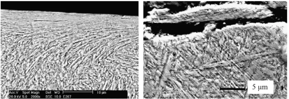
In addition, micro-cracks were observed at the extremity of the sub-surface in contact with the disc (Fig. 9a). Detailed observa-tions revealed that individual or few-layer “multilayered” lamellar laths are locally ruptured, forming the inter-lamellar micro-cavities. Theses micro-cavities coalesce and form sharp micro-cracks prop-agating under shear stresses in an inter-lamellar mode along the sliding direction (Fig. 9). It is generally asserted that when such
Fig. 7. A typical hot forging die after 1000 shots of billet at 1100◦C (Tool in
X32CrMoV12-28 47 HRC): note drastic plastic elongation of tempered martensitic laths and short cracks filled with oxides.
Fig. 8. SEM micrographs of the pin sub-surfaces versus different durations of friction (700◦C, 20 N). Note: sliding direction is from right to left.
Table 4
Maximum and mean thicknesses of the plastically sheared pin’s sub-surface region for various friction durations.
Friction test durations (s) 120 300 600 900 3600
Thickness (!m) affected by plastic deformation (!m) or “Sub-surface Deformed Zone” (SDZ) Max value 5 5 5 6 9
Min value 4 4 4 5 6
micro-cracks initiating in the sub-surface attain the free surface, debris are formed.Fig. 9b shows a thin debris worn out from the pin surface similar to the debris that are emitted by wear delamination mechanism[19].
As mentioned previously, friction experiments are conducted under constant normal loading. Nevertheless, it is admitted that the normal loading is not truly constant, and neither are the local stresses. The asperities, for example, contribute to these variations of “local” stresses. It can also be considered that the tangential forces are asymmetric. The local micro-strain accumulations there-fore take place under non-equivalent back and forth amplitudes.
These local stress and micro-plastic strain variations are highly con-ceivable under the continuous rotational sliding of a pin on a disc, giving the local loading and cyclic nature of the Low Cycle Fatigue type[18]. This allows micro-cracks to initiate and propagate. As mentioned earlier, under asymmetric cyclic loadings, the tool steels investigated here present symptoms of cyclic “ratchetting”. The accumulation of shear strains ultimately achieves the shear rupture ductility strain along the shear bands and forms the micro-cavities. The complex micro-cavities and micro-cracking interactions and their combined effects lead to the formation and emission of debris.
Fig. 10. A schematic representation of debris emission from the highly sheared
layers on the pin surface according to the “equivalent damage cycle (EDC)”.
4. Wear model
4.1. Definition of equivalent damage cycle
The micro-structure evolution of the pin sub-surface confirms that the plastic deformation decreases in an inward direction. The location of micro-cavities or micro-cracking very close to the contact sub-surface indicates that only this region – a few microm-eters in depth – reaches the critical shear rupture ductility limit. This heavily sheared sub-surface region is a material-dependent characteristic and acts as the major damage process zone in the steady-state wear regime and also in the emission of debris. An “equivalent damage cycle” (EDC) process consisting of plastic defor-mation and subsequent abrasion with debris emission is proposed here.
The pin surface and sub-surface are highly deformed under local cyclic shearing stresses. The variation of local loadings induces the accumulation of the deformation cycle by cycle with a “mean” plastic strain increment. This deformation achieves an ultimate shear rupture ductile strain (critical shear ductility). It is supposed that beyond this limit, the sub-layer is ruptured and releases wear debris.
The zone where material is plastically affected is called the “Sub-surface Deformed Zone” (SDZ). In all friction tests, the SDZ thickness never exceeded 10 !m. The ultimate layer of the sub-surface where material flows is identified as the “Debris Process Zone” (DPZ) and has a constant “mean thickness”, “b”, along the whole sliding track (Fig. 10and[10]). It is considered that debris is emitted since the DPZ achieves the critical shear rupture strain (or critical shear duc-tility). Following debris emission, the SDZ moves only inwards and its extent remains unchanged. The wear process starts again in the newly formed DPZ.
To estimate the value “b”, the plastic shear strain versus the sub-surface deformed zone needs to be measured. The wear height of the pin ("h in !m), which increases with the duration of the test, will be dependent on this value “b”.
4.2. Sub-surface strain estimation
The estimation of the plastic strain of the tempered martensitic lathes within SDZ was carried out by using the lath orientations [7](although this method is more appropriate when the deformed layers are thicker than 10 !m). In this approach, two angles ($) and (%) are measured along curled laths, in fact depicting the plastic shear flow lines (Fig. 10). By slope-change measurement method it is possible to estimate an equivalent shear plastic strain “"p” within
Table 5
Estimated shear plastic strain on top of DPZ for different friction durations.
Test duration (s) Estimated mean shear strain “"p” (%)
120 268 300 371 600 254 900 287 3600 ∞ SDZ (Eq.(1)). "p=tan % − tan &√
3 (1)
The estimated equivalent shear plastic strains are presented in Table 5. As can be observed, the estimated shear stain is always greater than 100% and, as is the case on the extreme surface of the DPZ, it can become greater than 1000%.
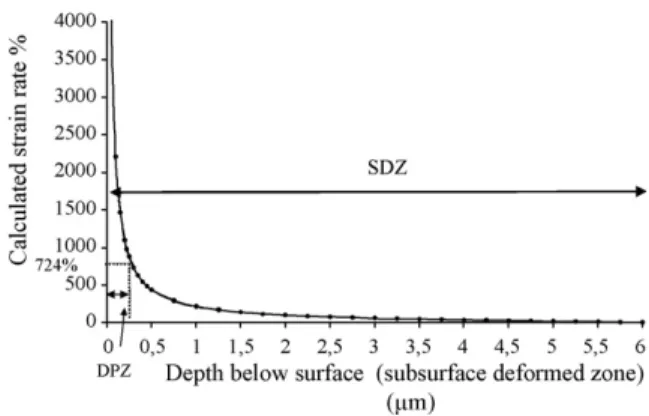
Authors[8,9]have reported for the estimated plastic shear strain distribution inwards from the contact surface has an exponential trend. Therefore, we have used the same trend to fit our experi-mental measurements of equivalent shear plastic strain “"p” versus depth (Fig. 11).
The strain decrease in depth is rather abrupt in the first few micrometers. Assuming that DPZ achieves the shear ductility “"c= 724%” measured by torsion test at 640◦C (Table 2), this means that the thickness “b” is estimated as 0.3 !m of the SDZ (Fig. 11). This is only about 5% of the total affected SDZ depth. It is impor-tant to mention that the estimated “b” may in fact underestimate the actual SDZ thickness, since only the residual part of the already plastic-shear-worn surface is visible during post-mortem measure-ments.
4.3. Critical shear ductility
The equivalent damage concept “EDC” is consisting of 4 steps. (i) Plastic deformation of the sub-surface, (ii) plastic deformation accumulation, (iii) rupture of the deformed layer and (iv) debris emission.
The EDC is based on the concept of incremental plastic strain accumulation. When the accumulated plastic strain attains the shear ductility ("c), local rupture occurs. The shear plastic accu-mulation (cyclic ratchetting) is a relevant process to represent the EDC that results in the height loss of the pin ("h in !m). Therefore, a constant strain increment #εr(per cycle) is introduced.
The strain increment was evaluated by finite element simula-tions (FEM)[32]of a pin on a rotating disc using ABAQUSTM6.2. A mean strain of all surface elements was calculated to estimate a mean increment strain of (#εr) about 1.14% per cycle. It should be emphasized that even if the ratchetting-type strain increment #εr
Table 6
Comparison of experimental and predicted wear heights.
Friction duration (s)
120 300 600 900 3600
Total number of cycles, N (×1000) 7.9 19.7 39.3 58.9 235.8
Measured mean affected thickness by plastic strain (!m) 4 4 4 5 6
Worn thickness, b (!m) (5% of the SDZ) 0.20 0.20 0.20 0.25 0.3
Shear ductility, "c(%) 724
Constant strain increment per cycle #εr(%/cycle) 1.14
Worn height, "h (!m) Calculated values (predicted) 2.5 6.2 12.3 23.1 111
Experimental mean values 10 18 21,5 22,5 87
can change upon the friction and the wear loading conditions, it is considered as constant per cycle and per number of cycles to failure (Nf).
Therefore, the number of cycles to failure of DPZ “Nf” is estimated
from the ratio between the shear ductility and the strain increment (Eq.(2)).
Nf=#ε"c
r (2)
The total duration of the friction test is converted into a num-ber of cycles “N” corresponding to the total sliding length “d”, for the given friction test, divided by the diameter of the circular pin contact surface (2a) (Eq.(3)).
N =
v
(2a)× t (3)With d =
v
× t (m) where “v
” is the disc rotating speed (m/s), “t” is the friction duration (s) and “a” is the initial pin contact radius (10−3m).It is assumed that under steady-state wear regime, the pin height loss ("h in !m), can be modelled as a linear function of the DPZ thickness “b” by considering the number of cycles to failure (Nf) and the total number of cycles specific to the test duration (N) (Eq. (4)).
"h =
!
Nb f"
× N (4)
Following the determination of the above mentioned parame-ters (
v
, b, N, Nf, #εr, "c) for the X38CrMoV5 (AISI H11) pin, the wear height "h was predicted by Eq.(5)."h =
!
Nb f"
× N =b × #ε" r c × N =v
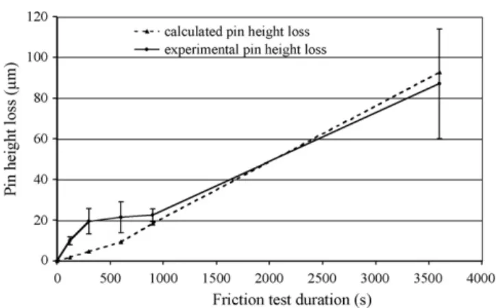
× t × #εr (2a) × "c × b (5) The experimental and predicted wear results (wear height "h) for all friction experiments at different durations are compared in Table 6andFig. 12.Fig. 12shows the good correlation between calculated (pre-dicted) and experimental wear height for all friction tests performed between 900 and 3600 s. As reported inTable 6and seen inFig. 2, predicted wear height is underestimated for short period experiments. As pins are initially at RT, for short-time experiments, the periods of the wear under transient temperature and steady-state temperature regimes become very comparable. It is assumed that the critical strain to fracture (rupture ductility) is constant for the steady-state regime but it is known that the rupture ductility decreases with lowering the temperature. The use of a lower rup-ture ductility value, for short-time tests, could thus be expected to lead to greater wearing heights.
In addition, the strain increment is also temperature-dependent and it can increase with temperature. This could explain the higher experimental and estimated wear height for short-time tests. The next step in the development of the model would be an expression of the different parameters as a function of time and temperature.
Fig. 12. Comparison between experimental and calculated wear heights of
X38CrMoV5 at 700◦C.
Another point to take into account is that the model consid-ers that an “equivalent” height is removed (expressed as a mean thickness b) over the whole pin contact surface. The entire wear surface of the pin does not break with a value of “b” strictly at the same time. At this stage of development of the model, X38CrMoV5 AISI-H11 thermoplastic softening and the sliding speed effects are not taken into consideration in FEM simulations. In fact, the slid-ing speed is assumed to be sufficiently slow (isothermal condition) for frictionally generated energy not to have a drastic influence on the temperature (700◦C) nor thus on the material behaviour. As mentioned, the thickness of the sub-surface zone affected by the plastic deformation must be larger than the visible experimentally observed and measured thicknesses.
Finally, it is agreed that the measured height loss ("h) can cor-respond to Archard’s law, because Archard’s law is also a wear law based on dissipated energy. The main difference between Archard’s law and the wear model presented in this paper is found in a scale level aspect. Archard’s law can be considered as macroscopic and this new model gives a physical view of the description of the wear mechanism (in the case of this steel grade and more precisely in the case of this typical micro-structure).
5. Conclusions
These investigations examine the friction and wear behaviour and the wear mechanism of a double-tempered martensitic tool steel X38CrMoV5 AISI-H11 (47 HRC, as pin). A high-temperature pin-on-disc tribometer was used with a flat surface pin, X38CrMoV5 AISI-H11-47 HRC and a mild XC18 disc.
It was observed that the whole sub-surface of the pin contact area suffered significant plastic deformation. Post-mortem SEM observations showed that parallel-juxtaposed “strip-like bands” or a lamellar “multilayered” micro-structure, are formed on the
sub-surface along the sliding direction. The lamellar “multilay-ered” micro-structures revealed that lathes are heavily elongated, as much as 300% or more. Identical plastic deformation and wear mechanisms are invariably observed in a “steady state friction ver-sus time” regime.
A new wear model is proposed based on cyclic plastic strain accumulations (the cyclic ratchetting concept) and the shear duc-tility criterion as a local failure process mechanism. It is considered that when the cumulative shear plastic strain at the sub-surface attains a critical strain limit (shear rupture ductility), the indi-vidual lamellar layers – or a small number of them – are locally ruptured, forming the inter-lamellar cavities. These micro-cavities coalesce and form sharp micro-cracks that propagate under shear stresses. This propagation is along the sliding direction and mostly takes place in an inter-lamellar manner which eventually leads to debris emission. Interrupted tests show that the pin geom-etry (flat surface) enhances the ejection of wear debris out of the contact surfaces and thus the debris flow does not significantly participate in the wear mechanism.
The model takes into account the mean strain increment (#εr), the number cycles (N, related to disc rotation speed), a characteristic material-dependent sub-layer wear thickness (b) and the critical strain to fracture (shear rupture ductility, "c). The average plastic strain increment is estimated by FEM numerical simulation of the friction of pin-on-disc.
A very good correlation between the experimental and pre-dicted wear heights versus number of cycles or time is obtained. The deviation is less than 20% for high test durations. The model underestimates the wear heights for the short-time tests due to the transient effects prevailing in the initial regimes of friction versus time experiments.
Acknowledgements
The authors would like to acknowledge Aubert&Duval for tor-sion experiments and delivery of steels free of charge and PSA for financial support during different stages of this work.
References
[1] H.C. Meng, K.C. Ludema, Wear 181–183 (1995) 443–457. [2] J.F. Archard, J. Appl. Phys. 24 (1953) 981–988.
[3] J.H. Kang, I.W. Park, J.S. Jae, S.S. Kang, J. Mater. Process Technol. 96 (1999) 53–58.
[4] R.S. Lee, J.L. Jou, J. Mater. Process Technol. 140 (2003) 43–48. [5] K. Mahjoub, Ph.D. Thesis, Ecole des Mines de Paris, 1999. [6] Y. Torre, Ph.D. Ecole des mines de Paris, 1984.
[7] J.H. Dautzenberg, J.H. Zaat, Wear 23 (1973) 9–19.
[8] M.A. Moore, R.M. Douthwaite, Metall. Trans. A 7A (1976) 1833–1839. [9] A.T. Alpas, H. Hu, J. Zhang, Wear 162–164 (1993) 188–195.
[10] B. Venkataraman, G. Sundararajan, Acta Mater. 44 (2) (1995) 461–473. [11] A. Kapoor, Wear 212 (1997) 119–130.
[12] S.M. Hsu, M.C. Shen, A.W. Ruff, Tribol. Int. 30 (5) (1997) 377–383. [13] D.A. Rigney, Tribol. Int. 30 (5) (1997) 361–367.
[14] J.P. Hirth, D.A. Rigney, in: F.R.N. Nabarro (Ed.), Dislocations in Solids: Application and Recent Advances, North-Holland Publishing Company, 1983.
[15] W.M. Rainforth, Wear 245 (2000) 162–177. [16] A. Kapoor, et al., Wear 200 (1996) 38–44. [17] F.J. Franklin, et al., Wear 251 (2001) 949–955.
[18] A. Kapoor, F.J. Franklin, Tribol. Wear 245 (2000) 204–215. [19] N.P. Suh, Wear 44 (1977) 1–16.
[20] P.W. Bridgeman, Studies in Large Plastic Flow and Fracture, Mc Graw-Hill, New York, 1952.
[21] H. Ll, D. Pugh, The Mechanical Behaviour of Materials Under Pressure, Elsevier Materials Science Series, 1970.
[22] C. Vergne, et al., Wear 250 (2001) 322–333. [23] O. Joos, et al., Wear 263 (2007) 198–206. [24] O. Barrau, et al., Wear 263 (2007) 160–168.
[25] O. Barrau, et al., Proceedings of the 6th International Conference on Tooling, Karlstad, 2002, pp. 81–94.
[26] N. Mebarki, et al., Proceedings of the 6th International Conference on Tooling, Karlstad, 2002.
[27] D. Delagnes, et al., Proceedings of the 5th International Tooling Conference: Tool Steels in the Next Century, Montan Universität Leoben, Austria, 29 September, 2001, 1999, p. 10.
[28] C. Daffos, et al., in: G. Biallas, H.J. Maier, O. Hahn, K Hermann, F. Vollertsen (Eds.), Proceedings of the High-temperature Fatigue CAMP 2002, Parderborn, 3–4 April, 2002, pp. 56–63.
[29] S. Jean, et al., Proceedings of the 5th International Tooling Conference: Tool steels in the Next Century, Montan Universität Leoben, Austria, 29 September, 2001, 1999, p. 10.
[30] A. Oudin, et al., in: L. Rémy, J. Petit (Eds.), Proceedings of theTemperature– Fatigue Interaction of 9th International Spring Meeting of SF2M, ESIS Publi-cation 29, Elsevier, Paris, 29–31 May, 2001, pp. 195–201.
[31] V. Velay, et al., Int. J. Plast. 22 (3) (2006) 459–496.
![Fig. 3. Stress-controlled experiments performed at 300 ◦ C (left), 500 ◦ C (right) (ini- (ini-tial total strain #ε = ±0.8%) [31].](https://thumb-eu.123doks.com/thumbv2/123doknet/11616614.303853/4.892.470.840.282.557/fig-stress-controlled-experiments-performed-right-total-strain.webp)