ADVANCED MANUFACTURING
METHODS FOR SYSTEMS OF
MICROSYSTEM
NANOSPACECRAFT – STATUS
OF THE PROJECT
P. Rochus(1), JY. Plesseria(1), A. Corbelli(2), C. Masse(3), O. Rigo(4), L. Pambaguian(5), B. Bonvoisin(5)
(1) Centre Spatial de Liège – Université de Liège, avenue du Pré-Aily, B-4031 Angleur,
Belgium, jyplesseria@ulg.ac.be (2) ALMASpace S.r.l, via Filippo Guarini, 13,
I-47121, Forli (FC), Italy, alberto.corbelli@almaspace.com (3) Thales Alenia Space – France, 100 Boulevard du Midi, F-06150, Cannes, France, christian.masse@th alesaleniaspace.com
(4) SIRRIS, Liège Science Park, 12 rue du Bois saint Jean, B-4102 Seraing, Belgium,
Olivier.Rigo@sirris.be
(5) ESA-ESTEC, 1 Keplerlaan, NL-2200 AG Noordwijk, The Netherlands, Laurent.Pambaguian@esa.int
ABSTRACT
In the frame of an ESA TRP project, CSL, SIRRIS, ALMASpace and TAS-F associated to evaluate advanced manufacturing methods for application to space hardware.
The state of the art of the new manufacturing methods, including additive manufacturing but also advanced bonding, j o i n i n g a n d s h a p i n g t e c h n i q u e s h a s b e e n reviewed. Then three types of case studies have been developed successively. The first type was a re- manufacture of an existing piece of hardware using advanced techniques to evaluate if there is some potential improvement to be achieved (cost, production time, complexity reduction). The second level was to design and manufacture a part based on the application requirements. The last level was to design and manufacture a part taking into account the subsystem to which it belongs. All case studies have been tested in terms of achieved performances and resistance to the mechanical and thermal environment.
1. INTRODUCTION
During the two last decades, many manufacturing technologies matured to a level compatible with demanding applications such as those of the space sector. Among these Additive Manufacturing Technologies are aiming at producing parts by adding material only where needed instead of removing large amount of material from a massive bloc. Other appealing technologies allow joining using low energy levels compared with conventional welding or brazing; this is the case of friction stir welding or magnetic pulse welding. More material processing technologies exist allowing shaping complex forms starting from a sheet of
material.
The above manufacturing technologies are on paper extremely well suited to space hardware as they allow conceiving “made to measure” hardware at an affordable cost. However, it is still extremely challenging using those as, to maximize the potential benefit they can bring, their implementation within a manufacturing chain has to be better understood.
ESA awarded to a consortium composed of CSL (Be), Sirris (Be), TAS-F (Fr) and Alma-Space (I) a Basic Technology Research Programme (TRP) contract aiming at studying capabilities offered by these advanced manufacturing technologies and addressing the end-to-end manufacturing process, starting from early design phase till functional testing of the part. To do so, three levels of part design complexity have been considered:
Level 1: part design individually optimized i.e. slightly modifying a conventional design
Level 2: part design driven by the application requirements, i.e. designing the part and the manufacturing flow-chart together to maximize the part performances.
Level 3: part design driven by the subsystem to which it belongs, i.e. designing the part and the manufacturing flow-chard together to maximize the sub-system performances.
The experience acquired on lower part complexity was perused and fully taken into account while designing the level 2 and level 3 parts. The complementary expertise of the partners including materials & processes engineers, system engineers, designers and end-users was also used to maximize the performances of the parts. The new and conventional manufacturing technologies were combined also toward the same objective.
2. STATE OF THE ART OF ADVANCED MANUFACTURING METHODS
This first step of the project has been to summarize the progress made in different manufacturing technologies and to present them to the partners implied in the project.
The first techniques reviewed were the metal additive technologies. These techniques are mainly based on the building of a part layer-by-layer. At each step, a layer of powder (or paste or liquid) is set on the already built part and a power source (laser, electron beam) locally melts the new layer that connects to the previous one. This process is repeated for the full construction. In the recent years, direct metal manufacturing has become possible and this allows reaching densities and properties close to standard materials. New techniques by laser or electron beam melting (LBM or EBM) allow direct melting of the pure metallic powder and realization of a final part.
Another method reaching good level of maturity is the laser cladding in which the metallic powder is directly injected on the part in parallel with the laser beam. This avoids the use of powder bath and allows building in three dimensions. This method is used to repair parts by adding material locally. This is extensively tested for maintenance of turbine blades.
Another technique investigated is the aerosol jet printing. This technique is used to locally “print” different types
of coating on the surfaces. The material to be printed is accurately projected on a surface then directly sintered by a laser. The technology allows deposition of various types of materials, only depending on its viscosity and its ability to be transformed in droplets. This technique has the advantage to only locally heat the substrate to avoid damages. Adequate control system also allows printing on non-flat surfaces (2 ½ D).
The joining and welding techniques have been reviewed. The advanced techniques identified are the friction stir welding, laser welding, electron beam welding.
In the frame of the project, salt dip brazing has also been used. In this technique, applicable to aluminum alloys, parts are assembled and junctions are covered with a paste filled with a different alloy. The assembly is then dipped in a salt bath in order to melt the filled paste and allow the filler metal to enter the junction and ensure good mechanical connection of the parts.
3. LEVEL-1 CASE STUDIES
3.1. Structural Case for Space Mechanism
Figure 1. Structural Case for Space Mechanism
This piece is the main part of the SADM (Solar Array Drive Mechanism). This structural part received the different components equipping the mechanism. In the front side are mounted the balls bearing and the potentiometer, in the back side the collector and the stepper motor. The piece is strongly mechanically loaded because it makes the link between the solar generator and the spacecraft interfaces, and, in the same time, strongly thermally stressed because of the motor and the collector closeness.
The purpose of this level one study is to manufacture the part as it is designed for conventional manufacturing method i.e. turning, milling, drilling; starting from a TA6V forged block or thick plate.
It has been decided quite rapidly to build this part by electron beam melting. This technique is quite suitable for the building of large titanium parts.
In comparison with laser beam melting, the electron beam melting is performed at higher temperature meaning that the residual thermal stresses are reduced and that no annealing treatment is required. This technique is also faster and can be useful in reducing production costs. The drawbacks are a higher surface roughness and slightly smaller accuracy. Additional care is also required to manage the charging of the powder. Indeed, the powder electrical conduction is small and this generates accumulation of charges that can, at a certain point, generates a sudden blow of the
powder, causing interruption the job. Several techniques exist to minimise the risk.
The design changes were minimal, only few supports were added for the manufacturing process. Several post- machining operations are required in order to remove these supports but also to ensure the correct geometry and surface finishes of the interfaces.
This first experience of the project highlighted several points to be taken into account for future manufacturing. Apart from the basic verification processes to be adapted, the importance of correct supporting structure has been put in evidence. This supporting structure is important on a mechanical point of view but also on a thermal point of view. These supports shall allow melting heat evacuation in a sufficient way to avoid local overheating and support deformation.
Another goal of the supports is also to support the part during post-machining. This post-machining is required for some critical interfaces to ensure dimensions and surface shape. Some flanges in this case study, that were initially built in a way to ensure local stiffness during standard machining, were not supported correctly anymore when the part came out of the building process in its almost final shape.
Figure 2. Final part manufactured by EBM
Another point highlighted in this case study is the necessity to correctly define the post machining steps and among others, the way the part will be aligned on the machine. Indeed, the advantage of the additive manufacturing is having free form surfaces but at some point the positioning references on the standard tools shall be clearly defined in order to ensure that the general orientation of the part with respect to the post- machined interfaces is correct.
Finally it was highlighted that all small features shall be clearly defined and that a manufacturing strategy must be elaborated.
A part has finally been fully manufactured and some static testing was applied. These tests showed stiffness slightly lower than the standard part while measurements on samples indicated that the mechanical properties should be similar to standard titanium alloy. Further comparison could not be performed since no original part was available to compare test results.
3.2. Reaction/Momentum Wheel Housing Assembly
ALMASat fleet spacecraft’s equips on board one or more Reaction/Momentum wheels, in order to counteract the effect of the environmental disturbance torques, such as the aerodynamic drag.
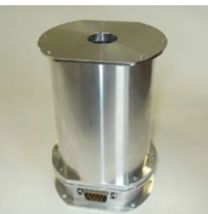
Figure 3. Reaction/Momentum Wheel Housing Assembly
Each actuator is mainly composed of an electrical motor and a flywheel, enclosed by an aluminum housing. The housing itself has been designed in modular parts, each of them aimed to support the installed equipment. For that reason, the most important requirement in the housing design and manufacturing is imposed first of all by the necessity to withstand the loads due to the launch and then to maintain in the correct position the rotating masses inside itself.
At the same time, the most challenging task is the reduction of the number and of the overall mass of parts composing the entire housing but at the same time easing the assembling procedure.
At present, the standard housing has a mass of 300 g and a first eigenfrequency at 350 Hz.
Expected technology improvements for the level 1 concern mainly the saving of material and manufacturing time required to realize a complete housing, still maintaining the same functional and performance requirements of mounting easiness, axiality and structural stiffness. In the frame of the activity, two manufacturing techniques have been tested with this case study, additive manufacturing for the bottom of the housing, and electron beam welding (EBW) techniques for the upper cylindrical parts.
The upper part was slightly adapted to be manufacturable with standard raw parts, i.e. tubes and plates. Some adaptations were also included to improve the welding efficiency by adding some shoulders at the location of the connections. Once these adaptations were performed, the different elements of the structure have been manufactured, controlled and finally assembled by EBW.
1. Figure 4. Design adaptation for EBW
2. The bottom part was made of stainless steel
by laser beam melting (LBM). Laser beam melting was required to ensure the correct tolerances on the dimensions but as the aluminum alloy powder was not available at that time, stainless steel has been selected instead. In this case again, several samples in various directions were built in order to evaluate the mechanical properties. Here again, a post machining of the interface surfaces and of the interface holes was performed.
Figure 5. Manufactured and assembled parts
The complete assembly revealed some fitting problems between the parts that were welded. Indeed some deformation due to the electron beam welding was visible. All corrections could be made by hand and finally the part was fully functional.
A test campaign was run at ALMASpace in order to compare the newly built part to and actual one. The results of the tests indicated that despite the differences (Stainless steel – aluminum), the global mechanical and thermal behaviour was very similar.
4. LEVEL-2 CASE STUDIES
4.1. Antenna support
This part is an attachment fitting to mount antennas on the satellite platform.
Figure 1 below shows the assembly.
Figure 6. Antenna Support
The overall size of the part is about 236 mm.
For this level 2 study the purpose is to perform a complete redesign of the part to take advantage of the freedom authorized by the additive manufacturing techniques. The goal is to design, manufacture and finally test an antenna support which is compatible with
interfaces requirements (on satellite structure side and antennas side) and compliant with stiffness requirement i.e. > 140Hz with mass objective of max 250g.
The first part of the activity was to implement topological optimization on the design.
The basic geometrical requirements on the part are the distance between the interface with the spacecraft and the antennas position and the allocated volume (including the waveguides and waveguide supports). The allocated volume has been defined in the optimization software as well as the required stiffness. The optimization was performed by trying to reduce the mass keeping the eigenfrequency in a correct range. This optimization is run in order to obtain full density material by using penalization parameters.
The obtained optimized design is quite “pixelised” (see
Figure 7) and it is necessary to redrawn it manually in a
compatible software in order to perform further analyses (strength analyses) and to obtain a finally useable design. Note that this last step has been further developed in parallel with this project in order to allow direct conversion of the smoothed geometry into useable format.
The manufacturing of the part has been sub-contracted to CITIM (D) that was able to build the part in aluminum alloy in due time. The part has then been post-machined by SIRRIS to ensure correct interfaces and dimensions.
The lessons learnt from the level-1 case study have been taken successfully into account. Reference transfer from LBM to standard machines has been made via a positioning pin and a plane. Nevertheless we still faced some difficulties during post-machining. Most of this phase was based on electrical discharge machining (EDM) to limit the tool loads on the optimized structure. It appeared that the various thicknesses of the part implied non uniform machining. This has been corrected by adapting the EDM electrode.
Figure 7. One step of the optimization
The final part was then submitted to a qualification sequence consisting in vibration test and thermal cycling test. The goal was to verify the eigenfrequency, the strength and the geometrical stability. Fringe projection 3D measurements were performed before and after each environmental test to confirm that the deformations of the structure remain largely within requirement.
Figure 8. Built part prepared for thermal cycling test
The qualification campaign was fully successful. The eigenfrequency was in the expected range and the high level sine applied (20-g) didn’t damage the structure. The thermal cycling revealed no problem. All mechanical testing were performed with dummy masses representing the antennas and the waveguide.
4.2. ALMASat-class Microsatellites Modular tray
ALMASat fleet spacecraft structures are composed by a set of stacked modular aluminum trays. Each tray contains a specific subsystem or equipment and the resulting assembly is a solid cubical or prismatic structure typical of educational and low-costs satellites. Similar structural solutions have been developed by SSTL and various universities in the US.
The trays are realized by means of standard drilling and milling processes, in 6082 aluminum alloy. Traditional milling techniques have been used to realize the holes for connectors and harness. The manufacturing process has been divided into several steps from preliminary roughing out to final details definition.
In the past several attempts to realize the trays by casting have been made but the overall quality was poor and the costs comparable to traditional machining operations.
Figure 9. Modular Tray
Expected technology improvements for the level 2 mainly the decreasing of manufacturing time required to realize a complete tray and also of the wasted material, still maintaining the same functional and performance requirements including the structural stiffness and the mechanical interfaces with subsystems and other trays, focusing moreover to the scalability of the part, for future missions. Alternatives to aluminum could be evaluated.
AML (Fr) company has been contacted based on their experience in salt dip brazing. This technique allows the junction of several aluminum parts in a single step. The element are first assembled and maintained together and a paste filled with aluminum powder is deposited at all junctions. By pre-heating in standard oven and then dipping the assembly in melted salt, the aluminum of the paste (which has a lower melting point) is melted and fills the interstice between the parts.
The assembled part is then thoroughly cleaned and heat treated according the T6 standard.
The advantage we see in this technique is the fact that the modular tray can be built from several standard parts (plates, simple milled parts…). Each part can be independently adapted ( connector h o l e s , interfaces). The size of the tray can be easily adjusted by changing dimension of some of the elementary parts.
A prototype of the modular tray has been manufactured by AML.
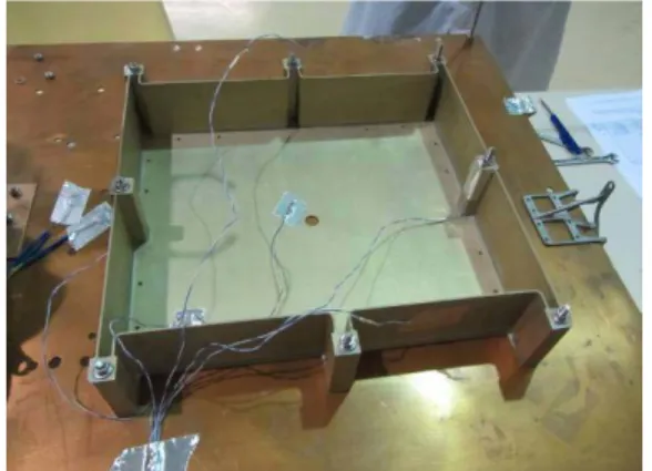
This part was inspected and was submitted to a qualification program consisting in vibration tests and thermal cycling. The vibration test was performed both on the built part and on an existing part allowing comparison. Fringe projection 3D measurements were performed before and after all testing in order to evaluate the deformation.
Figure 10. Modular Tray manufactured
The qualification was successful despite some geometrical deviation with respect to the manufacturing tolerancing. Nevertheless the modular tray was integrated at ALMASpace on existing hardware and it proved to be compatible with the need.
This part would be acceptable for flight based on qualification testing, nevertheless some additional defects were detected during tomography observation by ESTEC. Indeed, some of the gaps between the parts were not correctly filled by the melted brazing aluminum. It emphasized the fact that such a part would require some more prototyping to optimize local design of the junction between parts. Cost estimation (taking into account additional prototyping) indicates that this manufacturing solution would be comparable to the standard manufacturing method previously used.
5. LEVEL-3 CASE STUDY
5.1. Sun Sensor Housing
A custom fish-eye sun sensor has been developed by ALMASpace for spacecraft attitude determination, as a fundamental part of the ADCS subsystem. The sun sensor is enclosed in aluminum alloy housings in order to protect the dedicated optics and electronics.
The sun sensor is composed of a single optic and a PSD sensor whose output is averaged according to the quality of the acquisition. For this reason, the lens mounting requires a good manufacturing precision, together with the possibility to directly connect the sun sensor housing to the satellite structure.
The sensor is mounted internally and based on a fish- eye optical system: the housing has been designed to integrate both the lenses and the electronics in a unique solution with a not negligible saving in terms of mass and volume.
Figure 11. Sun Sensor
The housing has been realized by means of standard turning and milling processes, in 6061 aluminum alloy. Micromachining techniques have been employed in order to realize the connection for the electronic boards to the housing or the centering pin for precise mounting. The electronic boards have been realized with standard PCBs, with pin-to-pin connections between different boards.
On the basis of the activity done in the frame of the Level 1 and 2, the first expected improvement concerns the saving of material and manufacturing time required to realize a complete housing, still maintaining the same functional and performance requirements of mounting easiness and precision and structural stiffness. Additive manufacturing technologies have been taken into account for the realization of the parts.
Optimization has been introduced at design level to allow additional mass saving and to enhance the device mechanical properties, suggesting more complex geometries studied in order to provide a better integration of the sensor inside the spacecraft structure. Finally it has been evaluated to integrate the on-board electronics directly on the internal surfaces of the housing, to save space avoiding the manufacturing of at least one of the internal PCBs, plus the mounting screws and spacers.
The design lead to the use of only 3 metallic parts for the sun sensor assembly: the bottom plate on which the detector electronic tracks will be printed by AJP, the inferior dome, closing the detector cavity, supporting the thread for the optical system and the power PCB and the upper dome holding the optical sub-system. These parts will be manufactured by SIRRIS in aluminum alloy by laser beam melting (LBM).
Figure 12. Cut view of the designed Sun Sensor
Preliminary evaluation of the printing of the circuit has been performed. First an insulating, space validated coating shall be applied on the support. NOA88 glue is used and application has been optimized to ensure reproducibility and flatness. Then the circuit is applied by depositing and directly sintering along the track a silver layer. Early measurements indicated that this type of track has a resistivity about 5 times higher than standard circuit tracks. It remains nevertheless sufficient for our application.
The manufacturing of this case study is running and it will be the last step of this project.
A full test sequence is also planned and we hope that it will be as successful as the previous ones.
6. CONCLUSION
This paper presents the work performed in the frame of this TRP from ESA. The goal was to review advances in the manufacturing methods and to apply them to different case studies in order to evaluate on real cases how these new techniques shall be implemented and what would be the impact on the way we are designing and manufacturing for space. The tested techniques are the electron beam welding of aluminum alloy, the electron beam melting of titanium alloy, the laser beam melting of stainless steel, the laser beam melting of aluminum alloy, the salt dip brazing of aluminum alloy and the aerosol jet printing.
These case studies were quite fruitful in lessons learnt. The major ones are the following. First, it is required to redefine the design phase in order to forget the automatisms of the standard manufacturing rules to only specify the important interfaces and tolerances. Secondly, the advanced manufacturing methods will not suppress the classical methods. In all cases, we had to post-machine the parts to ensure correct final dimensions and surface aspect. As a consequence, the manufacturing strategy has to be defined and taken into account as soon as the design phases to ensure that the final definition of the part can be reached at the end of all the manufacturing steps (reference holes, alignment planes…).
The use of advanced manufacturing methods still relies strongly on the technology providers (manufacturer) who have developed a strong experience with their production tools.
Finally the fact that we could work as a team implying the customers, the designers and the manufacturers improved largely the efficiency of the
work.
7. REFERENCES
1. RP-CSL-AMM-12001, Manufacturing and test report for mechanism housing
2. RP-CSL-AMM-12002, Manufacturing and test report for wheel housing
3. RP-CSL-AMM-12003, Manufacturing and test report for antenna support
4. RP-CSL-AMM-12004, Manufacturing and test report for modular tray
8. ACKNOWLEDGMENT
ALMASpace, SIRRIS, TAS-F and CSL would like to thank ESA for the financial and technical support in the frame of this project.
The partners also want to thank the different sub- contractors implied in the project at different levels i.e. CEWAC (Be), AML (Fr), CITIM (D) as well as all persons who provided support and information about the advanced manufacturing methods.