OATAO is an open access repository that collects the work of Toulouse
researchers and makes it freely available over the web where possible
Any correspondence concerning this service should be sent
to the repository administrator:
tech-oatao@listes-diff.inp-toulouse.fr
This is an author’s version published in:
http://oatao.univ-toulouse.fr/19743
To cite this version:
Martin, Rautenberg
and Poquillon, Dominique
and Pilvin, Philippe
and Grosjean, Catherine
and Cloué, Jean-Marc and Feaugas, Xavier
Thermal isocreep curves obtained during multi-axial creep tests on
recrystallized Zircaloy-4 and M5™ alloy. (2014) Nuclear Engineering and
Design, 269. 33-37. ISSN 0029-5493
Thermal isocreep curves obtained during multi-axial creep tests on
recrystallized Zircaloy-4 and MS
™alloy
M.
Rautenberg
a,
b,
*
, D. Poquillon
b, P. Pilvin
c, C. Grosjean
a,
b,j.M. Cloué
a, X. Feaugas
d• AREVA, AREVA NP, 10 rue Juliette Récamier, 69456 Lyon, France b C/RIMAT, CNRS/UPS/INPT, 4 allée Emile Manso, 31030 Toulouse, France c LIMATB, University Bretagne-Sud, rue de Saint-Maudé, 56321 Lorient, France d LEMMA, Université de La Rochelle, Avenue Michel Crépeau, 17042 La Rochelle, France
ABSTRACT
Zirconium alloys are widely used in the nuclear industry. Severa) components, such as cladding or guide tubes, undergo strong mechanical loading during and after their use inside the pressurized water reactors. The current requirements on higher fuel performances lead to the developing on new Zr based alloys exhibiting better mechanical properties. In this framework, creep behaviors of recrystallized Zircaloy-4 and MS™, have been investigated and then
compared. In order to give a better understanding of the thermal creep anisotropy of Zr-based alloys, multi-axial creep tests have been carried out at 673 K. Using a specific device, creep conditions have been set using different values of f3 = azz!a00, O'zz and a00 being respectively the axial and hoop creep
stresses. Both axial and hoop strains are measured during each test which is carried out until stationary creep is stabilized. The steady-state strain rates are then used to build isocreep curves.
Considering the isocreep curves, the MS™ alloy shows a largely improved creep resistance compared to the recrystallized Zircaloy-4, especially for
tubes under high hoop loadings (0 < f3 < 1 ). The isocreep curves are then compared with simulations performed using two different mechanical models. Mode! 1 uses a von Mises yield criterion, the model 2 is based on a Hill yield criterion. For both models, a coefficient derived from Norton law is used to assess the stress dependence.
t. Introduction
Zirconium alloys are widely used in nuclear applications, and more specifically in the production of fuel rad cladding tubes. In service, these components are subjected to complex thermo mechanical loadings but also to other solicitations (irradiation, corrosion, etc.). ln order to improve design and lifetime of such structures, mechanical models have been developed. Therefore, to fit mode! to reality, testing creep behavior of fuel claddings is essential. The creep anisotropy of these components is well known (Brachet et al., 1998) and mainly due to the cold pil gering rolling process used to form the tubes and inducing an anisotropie crystallographic texture in the polycrystalline material. Polycrystalline models dedicated to Zirconium alloys have been developed (Miller, 1987; Brenner, 2001; Pilvin, 1990), taking into account the specific distribution of grain orientations which is opti mized in cladding tubes because of its strong influence on the mechanical behavior (Delobelle et al., 1996; Priser et al., 2009). The accuracy of these models was observed for zirconium alloys by several authors ( Geyer, 1999; Fandeur et al., 2001 ; Onimus and Béchade, 2008). However, they are not yet used for design * Corresponding author. Present address: EDF, SEPTEN, 12-14 Avenue Dutriévoz, 69628 Villeurbanne Cedex, France.
E-mail address: mrautenb@gmail.com (M. Rautenberg).
http: / /dx.doi.org/10.1016/j.nucengdes.2013.08.002
applications, as computation times would be too important. In the future, polycrystalline models could nevertheless be considered as a virtual creep testing device, whose results could be used to build simplified models. The most suitable models may be chosen by comparison with experimental results. In a previous study, creep tests have been carried out on recrystallized Zircaloy-4 and MS™ (Grosjean et al., 2007, 2009a,b) with multiaxial loadings at 673 K. During these experiments, strain evolutions were measured bath in the axial and hoop directions to allow a 3-D characterization of the creep anisotropy.
The aim of the present paper is to compare two simplified models using an isotropie or an anisotropie formulation of the equivalent applied stress. Their ability to fit experimental data is presented for bath investigated alloys. Thus, in the first part of this paper, we will detail the material and the device used for the creep tests. Then the experimental results and the tested models will be presented.
2. Materials, experimental device and creep tests
The investigated zirconium alloys are recrystallized Zircaloy-4 and MS™ (Table 1). The device used (CAT.0 for Creep Advanced Testing) have been especially developed for multiaxial tests on tubes (Grosjean et al., 2007, 2009a,b). lt allows an axial load up to S kN and an internai pressure up to 200 bars. Axial and hoop strains are measured by laser extensometers located in front of the
Table 1 Chemical compositions. Recrystallized Zircaloy-4 MS™ Sn 1.29wt% <50ppm Fe 0.22wt% <400ppm
small quartz windows of a radiative furnace that surrounds the tested sample. The specimens are 130 mm long segments of tubes. They present an outer diameter between 9.5 mm and 11.5 mm and a
ë11 s;l
sI;
1 E'22 s;2 �2 E'33sh
�3 €= + E'12sh
s1;2 E'23 s;3 �3 ë13sh
s1;3thickness between 0.5 mm and 0.6 mm. Ail tubes were formed by a cold pilgering rolling process and were then subjected to a recrystallisation heat treatment, resulting in a fully recrystallized hexagonal close packed microstructure. This cold-working form ing process induces anisotropie crystallographic textures which are comparable for both investigated alloys. C-axes of the grains are mainly orientated around ±30° of the radial direction resulting in a mechanical anisotropy (Grosjean et al., 2009b; Priser et al., 2011 ).
Ail the tests were realized at a temperature of 673 K. Creep tests were stopped when stationary creep strain rate was stabilized.
Table 2 shows the different stress levels used for the present study, in order to scan different biaxiality ratios fJ=azz/a00, azz and a00 being respectively the axial and hoop creep stresses. Stresses are normalized with a division by ai, the applied axial stress for a mea sured equivalent strain rate of 3.5 x 1
o-
8 s-1, with a hoop stress set to zero on the MS™ alloy.3. A simplified macroscopic modeling of creep behavior A partition of the elastic and viscoplastic strain is used:
Table2
(1) (2)
Applied hoop and axial creep stresses for the experimental data used to build the models. f3 00 -00 3 2.65 1.5 0.75 0.5 0 MS™ aee/a, 0 0 0 0 0 0.42 0.35 1.28 1.42 1.10 1.45 1.25 1.25 azz/a; 0.75 0.93 1.04 -0.83 -1.04 1.25 0.93 1.50 1.28 1.42 0.83 1.09 0.63 0 Recrystallized Zircaloy-4 aee/a, azz/a; 0.00 0.83 0.43 1.13 0.92 1.38 1.30 1.28 1.27 0.94 1.25 0.63 1.25 0 Cr 0.12wt% <50ppm 0 0.12wt% 0.146wt% Nb 1wt% Zr Bal. Bal.
where C is the Hooke tensor of the material. If the yield stress of the proposed mode! is anisotropie, the el as tic part of the be havi or will be supposed isotropie. Thus, using tensorial notations:
C11 C12 C12 C12 C11 C12 0 C= C12 C12 C11 (3) and (44 0 C44 (44
The coefficients ofC can easily be deduced from the Young modulus E, the Poisson's ratio v and the shear modulus G:
vC44 vG .
C44=G; C12=
1_2v = 1_2v, C11 =C12+C44 (4) The dislocation density Ps for each slip system s is defined as fol lowed:
dps IYsl
( 1 ) )2
- = - --2Ydt b L sPs -B(Ps -Po (5) where b is the Burgers vector, L is the mean free path length of dislocations, Ys the annihilation distance, Ps the dislocation density for the systems (Fandeur et al., 2001; Priser et al., 2011 ), and Ys its corresponding strain rate.
As the simplified mode! used does not discretize activated slip systems, the expression for the global dislocation density p is sim ilar to Eq. (5):
dp 1 dlëPI
( 1 ) 2
- = - x -- --2Ydt b dt L aP -B(p-Po) (6) where Ya stands for an average of the different Ys and sP is the equivalent plastic strain.
The evolution of work hardening R proposed is the following:
R = a0 + aGb.,fp (7)
where a0 corresponds to an initial yield strength and a to a harden
ing coefficient. Considering the activated slip systems in hexagonal close packed zirconium during creep at 673 K, the burgers vector b
can be taken as the lattice parameter (a) (Priser et al., 2011 ). To get dimensionless expressions from Eq. (6), a new internai variable q = b2 pis introduced, and the equation is then:
dq = dlëizl (� _ 2Yaq)-.!!.(q-qoJ2
dt dt L b b2
with
R = ao +aG.jq
If p is the cumulated viscoplastic strain, its rate is given by jJ: -�
p = 3ë . s
(8) (9) (10) In order to mode! multiaxial loadings, a simplified anisotropie mode) is proposed using a Hill criterion H2 for viscoplastic flow as detailed in Eqs. ( 11) and ( 12 ).
1,2% 0,8% 0,4% 0,0% -0,4% -0,8% creep strain
- -
Model 1 MS , ... Model 1 MS -ExpMS.,:zz (a) zz tt 1,2% 0,&% 0,4% creep duration (s) 0,0% 150 000 200 000 -0,4% zz tt --ExpMS_tt -0,&% creep straîn ,_-:;-S"'....--
-
-
...
--
...
---
--
...
...---
-.,,,.
...
,,,,....
/...
,,,..,,.
,,.
creep duration (s) ··.··.:,:.:..-!?O.QOO 100 000 150 000 200 000 -....:·:·�-,-:..:.;.:.,.,...,,,__
_
_
_
_
_
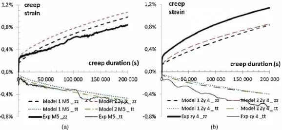
,., Model 1 Zy 4_ zz ... Model 1Zy4_ tt -Exp zy4_zz (b) ---del 2 Zy 4 _ zz - · Model 2Zy tt -- Exp zy 4 _ttFig. 1. Comparison between experimental data and models for axial creep tests. (a) Recrystallized Zircaloy-4, azz/a, =0.83 and (b) MS™, a zz/a, = 0.93.
with
{12) Assuming that for pure axial loading (when a00 and arr are set to
0), plastic flow occurs for a22 = a0, then using Eqs. (7), {11) and {12)
we get a relation between Hr and He:
He= 1-Hr. {13)
For an isotopie be havi or Hr = Hz and, as a consequence, in that particular case Hr=Hz =H0 =0.5 and Eq. {12) becomes the definition of the Von Mises criterion.
For the viscoplastic flow, the normality rule leads to: dsP = (f.)n
a� ifF>0
dt K
aa
(14)So ifa stands for the stress and D stands for the deviator operator then:
dsP _ 3 ( F ) n D(a)
Tt- 2 R Hz(a) (15)
To summarize, 10 different coefficients are used {E, v, n, K, a, L/b, Ya/b, B/b2, Hr, Hz}. They can be reduced to 8 ifwe setHr=Hz=1/2. Four experimental variables {t,
a, e,
T} are taken into account andthree internai variables (sP; p; q) are computed during the calcu
lations. For both materials, the software SIDOLO (Cailletaud and Pilvin, 1993) was used to fit the coefficients in order to minimize the difference between simulation and experimental data for axial and hoop strain. For ail simulations, the Young modulus and the Poisson's ratio were fixed to respectively 78,000 MPa and 0.37.
The first run of simulations was carried out with Hr =Hz= H0 = 0.5. This "model 1" corresponds to the classical
Von Mises isotropie criterion. The 6 remaining coefficients were identified on axial creep tests.
For the second run of simulations Hr and Hz were taken as free coefficients. This "model 2" corresponds to a Hill approach. The 8 coefficients of this model were identified using ail the tests ( axial and multiaxial creep tests).
4. Results
The optimizations which minimize the difference between sim ulated and experimental creep strain curves were carried out for both alloys and for both models.
Table 3 details the values obtained at the end of the optimiza tion process. The n exponent remains quite the same in any case. The initial yield strengths a0 are close to O. Model 1 allows a good
description of axial creep tests for both alloys (Fig. 1) but not for loadings in which the values of {3=azzfa00 is lower than 2 (Fig. 2).
Fig. 1 shows that with similar axial loadings, the MS™ alloy exhibits a lower strain rate than the Zircaloy-4. This tendency is confirmed for ail the tested loading directions.
Model 2 enables an anisotropie approach using Hill coefficients. We notice that this approach is more suitable as the optimization process leads to values of Hz that differs from O.S. Furthermore, creep anisotropy seems enhanced for the recrystallized Zircaloy-4 compared with the MS™ alloy.
Using a large experimental data (Grosjean, 2009), it is possible to compute for each alloy and for each biaxiality ratio f3 a Norton coefficient nexp_ The experimental data can be then interpolated in
order to determine "isocreep curves", i.e. the locus [a00; a22] for a
constant secondary strain rate, which is calculated using Eq. (16):
= A(avonMisest exp
(16) Besides, simulations are carried out with models 1 and 2 to determine which stress levels leads to a given secondary creep strain rate of 3.5 x 10⁻⁸ s-1 for each investigated biaxiality ratios.
6% 4% 2% 0% -2% -4% reep ::;train
.... •··
,••·· ,•··•'. .:S�:___...,...,_--r-==-,---;a,=--,.,-;::�èr. eep duration (s)
- - - ---- -1 -1 1 1 1 - - -5Q'.IDQ
---
---
100000--
150000 --Exp Zy4_tt ... · Mo del 1 Zy 4 _ tt - -"Model 2 Zy 4 _ zz-
-
. --"Exp Zy 4_ zz - - - Mo del 1 Zy 4 _ zz - · Model 2 Zy 4 _ tt Fig. 2. Comparison of experimental data, mode! t and mode! 2 for recrystallizedTable3
Value of models coefficient after identification using the data base of Table 1.
Coefficients E (MPa) (locked) v (locked) n K(MPa) a0 (MPa) Ci L/b Ya/b B/b2 (s-1) Hr H, ,..., ....!.... i5
---� 2.0 1.6 1.2 0.8 0.4 MS™Madel 1 (Von Mises) 78,000 0.37 5.83 1644 1.31 0.63 2181 51.8 0.42x 10--4 0.50 (locked) 0.50 (locked) ---exp. MS™ Model 2(Hill) 78,000 0.37 5.62 1801 1.32 0.627 1827 60.27 0.35 X 10⁻⁴ 0.514 0.368 ----mode!! ---model2 0.0 +----.----.--,.__ -.---.---0.0 0.4 0.8 1.2 cree /cri [-] (a) 1.6 2.0 Recrystallized Zircaloy-4 Madel 1 (Von Mises) 78,000 0.37 5.84 1647 1.35 0.35 1975 45.2 0.37 X 10⁻⁴ 0.50 (locked) 0.50 (locked) Recrystallized Zircaloy-4 Model 2(Hill) 78,000 0.37 5.97 1355 1.32 0.615 1834 50.3 0.42 X 10⁻⁴ 0.48 0.29 2.0 -.---� ---MS™ 1.6 · · · Recrystrallized Zircaloy-4 � 1.2 i5 � 0.8 0.4 0.0 ---�--��� �--�---0.0 0.4 0.8 1.2 1.6 2.0 cree /cri [-] (b)
Fig. 3. Isa creep curves for an equivalent strain rate of 3.5 x 10-• s-1 at 673K. (a) Isocreep curves obtained from mode! 1, model 2 and experimental data the MS™ alloy. (b)
Comparison between the investigated alloys.
This enables the plot of isocreep curves that can be compared to those obtained with the interpolation of the experimental data.
Examples of experimental and numerical isocreep curves are plotted in Fig. 3. Both models are not able to reproduce the creep tube resistance for stress biaxiality ratios between 2 and 0.5. But model 2 is, as expected, doser from the experimental data.
Isocreep curves of both investigated alloys have also been com pared. Results are plotted on Fig. 3b for a value of 3.5 x 10⁻⁸ s-1.
The MS™ exhibits a better creep resistance than the recrystallized Zircaloy-4, especially for biaxiality ratios below 1.
5. Conclusion
The present experimental results constitute an evidence of the creep anisotropy of zirconium recrystallized alloys. Effectively, the global shapes of the isocreep curves differ from what can be obtained using an isotropie criterion (mode) 1). This could mean that anisotropie considerations are more suitable for an accurate modeling. Despite the use of an anisotropie Hill criterion, model 2 is still not able to fit the experimental data for 0.5 < f3 < 2.
This region of the isocreep plot seems to exhibit a complex behavior that seems to be more alloy-dependant, as it is the only part of the ico-creep curve which has a different shape for the two considered alloys (Fig. 3b). The fact that a polycrystalline model could fit more easily the experimental creep strains and isocreep curves (Priser, 2011) can be interpreted in different ways. First, the higher number of considered parameters for this kind of model allows a better setting, on a multi-scale experimental data
( crystallographic texture measurements, TEM observations, tensile tests, etc.). However, a major explanation for the accuracy of this approach is the discrimination of the different activated slip sys tems. It can enable the model to fit the variation from "hard" to "ductile" creep behaviors more easily. Thus, cross-slip or secondary slip systems can be activated in different proportions according to the direction of Ioading and its orientation toward the crystallo graphic texture.
The strongly heterogeneous crystallographic texture of the stud ied zirconium alloys, combined to the limited possibilities of slip systems, is the principal explanation for the shapes of the isocreep curves. ln particular, the unusual curvatures for 0.5 < f3 < 2 are linked to a significant evolution in the repartition of dislocation glide ( Geyer et al., 1999). A similar explanation can be given to account for the linear evolution of the curves for 2 < f3 < oo and 0 < f3 < 0.5. And
linear shapes, as well as "too convex" shapes, cannot be globally described with quadratic criterions such as those used in the mod els presented. We can therefore assume that macroscopic models using equivalent stresses calculated with a non-quadratic Iaw, like the Hosford criterion (Hosford, 1972), would allow an improved accuracy.
Acknowledgements
The authors are grateful to Dr. M. Priser for his contribution to the modeling, and to K. Niang (AREVA NP - CEZUS) who provided the tubes.
References
Brachet, J.C., Béchade, J.L., Castaing, A, Le Blanc, L., Jouen, T., 1998. Relationship between crystallographic texture and dilatometric behaviour of a hexagonal polycrystalline material. Mater. Sei. Forum 529, 273-275.
Brenner, R., 2001. Influence de la microstructure sur le comportement en fluage thermique d'alliages de zirconium: analyse expérimentale et mise en oeuvre de méthodes d'homogénéisation. Université Paris XIII (Ph.D.).
Cailletaud, G., Pilvin, Ph., 1993. Identification and Inverse problems: a modular approach. Am. Soc. Mech. Eng. 33, 43.
Delobelle, P., Robinet, P., Geyer, P., Bouffioux, P., 1996. A mode! to describe the anisotropie viscoplastic behaviour of Zircaloy-4 tubes. j. Nucl. Mater. 135, 238.
Fandeur, O., Pilvin, P., Prioul, C., 2001. Modélisation du comportement mécanique du Zircaloy-4. J. Phys. IV 11.
Geyer, P., 1999. Comportement élasto-viscoplastique de tubes en zircaloy 4: approche expérimentale et modélisation micromécanique. Ecole Nationale Supérieure des Mines de Paris (Ph.D.).
Geyer, P., Feaugas, X., Pilvin, Ph., 1999. Modelling of the anisotropie viscoplastic behavior of fully annealed Zircaloy-4 tubes by a polycrystalline mode!. ln: Plas ticity'99, Cancun, Mexico, pp. 133-136.
Grosjean, C., 2009. Anisotropie de comportement en fluage thermique de tubes gaine et de tubes guide en alliages de Zirconium. Développement expérimentaux et résultats. Université de Toulouse (Ph.D.).
Grosjean, C., Poquillon, D., Salabura,j.-C., Cloué,j.-M., 2007. Fuel rod testing in creep conditions under multiaxial loadings: a new device and experimental results. In:
19th International Conference on Structural Mechanics in Reactor Technology, Toronto, Canada.
Grosjean, C., Poquillon, D., Cloué, J.-M., 2009a. Innovative creep device and anal ysis method applied to cladding tubes in Zirconium alloys. In: 2nd ECCC Conference-Creep and Fracture in High Temperature Components - Design a Life Assessment, Dubendorf, Germany.
Grosjean, C., Poquillon, D., Salabura, j.-C., Cloué, j.-M., 2009b. Experimental creep behaviour determination of cladding tube materials under multiaxial loadings. Mater. Sei. Eng. A 510-511, 332-336.
Hosford, W.F., 1972. A generalised isotropie yield criterion. J. Appl. Mech. 39, 607-609.
Miller, AK., 1987. Unified Constitutive Equations for Creep and Plasticity. Elsevier Applied Science, New York.
Onimus, F., Béchade,j.-L., 2008.A polycrystalline modeling of the mechanical behav ior of neutron irradiated zirconium alloys. J. Nucl. Mater. 384, 163-174.
Pilvin, P., 1990. Approches multi-échelles pour la prévision du comportement anélastique des métaux. Université Paris VI (Ph.D.).
Priser, M., 2011. Analyses multi-échelles du comportement en fluage d'alliages de Zirconium. Université de Bretagne-Sud, Ph.D.
Priser, M., Cloué, J.M., Pilvin, P., Poquillon, D., 2009. A mixed yield surface for modelingthe anisotropie mechanical behaviorofZirconium alloy. In: 20th Inter national Conference on Structural Mechanics in Reactor Technology, Helsinki, Finland.
Priser, M., Rautenberg, M., Cloué, j.-M., Pilvin, Ph., Feaugas, X., Poquillon, D., 2011.
Micromechanical approach of visco-plastic behavior of recrystallized zircaloy-4. J. ASTM lnt. 8, 10-29.