To cite this document: Pierl, Christoph and Chaudemar, Jean-Charles and
Lizy-Destrez, Stéphanie Application of the Systems Engineering methodology to the
design of the AOCS of an Earth Observation satellite. In: Complex Systems
Design & Management (CSD&M) 2012, 12-14 Dec 2012, Paris, France.
(Unpublished)
O
pen
A
rchive
T
oulouse
A
rchive
O
uverte (
OATAO
)
OATAO is an open access repository that collects the work of Toulouse researchers and
makes it freely available over the web where possible.
This is an author-deposited version published in:
http://oatao.univ-toulouse.fr/
Eprints ID: 6802
Any correspondence concerning this service should be sent to the repository
administrator:
[email protected]
Application of the Systems Engineering
methodology to the design of the AOCS of an
Earth Observation satellite
Christoph Pierl, Jean-Charles Chaudemar and St´
ephanie Lizy-Destrez
Institut Sup´
erieur de l’A´
eronautique et de l’Espace, Toulouse
April 18, 2012
Abstract
This document describes the application of enhanced functional flow block diagrams (eFFBD) on the attitude and orbital control system (AOCS) of an Earth Observation satellite. First requirements and constraints of the satellite and its mission have been identified. Afterwards, these re-quirements and constraints were used to design the eFFBD of the AOCS.
1
Introduction
Since the first satellites have been placed on orbit around the Earth, it is in-evitable for an optimal use to control its attitude and orbit. It is not sufficient just to install the satellite on its orbit with the desired orientation because of the space environment which disturbs the orientation and the shape of the or-bit of the satellite. Thus a subsystem becomes necessary which measures and computes the attitude, computes commands to correct the deviation and applies these commands. Such a subsystem is called attitude and orbital control system (AOCS).
So as to identify functional design patterns for the attitude and orbital con-trol system for an Earth Observation satellite, we decide to model it with the formalism called enhanced functional flow block diagram (eFFBD). This con-tains beside the modellisation of the AOCS also the modelling of the space environment and its influences, space debris and the de-orbiting at the end of the operational lifetime. Additionally to the de-orbiting modelling, it has to be mentioned, that the intended Low Earth Orbit (LEO) of the satellite lies in an environment which has been polluted with debris over decades. This fact makes it a dangerous area for space flight and satellite missions and to countersteer the pollution, the de-orbiting maneuver is considered.
The main problematic addressed in this article is complex. For this reason we need a Systems Engineering methodology. During the last decades it became more and more important to have tools, methods and processes available to
handle large projects along the life cycle of the studied system [1]. As this study focus mainly on the architecture process, the notation, used in the frame of this document is eFFBD.
Section 2 describes the context of the study. Section 3 gives an overview of the applied elements to design the eFFBD models. Section 4 contains the ap-plied eFFBD on the AOCS. Section 5 concludes the document and gives a brief outlook on future work.
2
Satellite and Mission
This section is dedicated to the description of the attitude and orbital control subsystem (AOCS) of a satellite. It describes the architecture of the system, the attitude and the orbit of the satellite. The information presented in this section are used as a basis to apply the eFFBD Systems Engineering approach on the AOCS, which is described in the follwoing sections.
2.1
Layered architecture
The introduction of a layered architecture to the AOCS allows to subdivide the satellite into different hierarchical layers representing functionalities. The architecture which is introduced in the paper consists of two functional layers. The opearational layer is the highest which concerns the different operating modes of a satellite: operational, safe, recovery and end of mission. The second layer is the functional layer which is managed by the operational and consists of functions to sense, detect and computes the attitude of the satellite and computes counter actions. In this layer, we are only concerned with the satellite control functionality[9] [10].
2.2
Attitude of the satellite
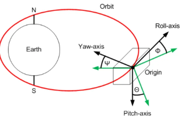
The attitude of a satellite is represented with respect to its yaw, roll and pitch axis of a local reference frame which is determined in the origin of the satellite. The reference frame and the locations of its axis are schematically pictured in fig. 1 [7]. In this figure, it is depicted that the yaw-axis is oriented nadir, the roll-axis is tangential to the orbit and the pitch-axis is perpendicular to the orbital plane or rather to the plane spaned by the roll- and yaw-axis. Differences between the local reference frame of the satellite to the local coordinates are represented by the angluars: Φ, Θ and Ψ. The AOCS in general has to be capable in order to provide a certain precision around all axis (roll / x, pitch / y, yaw / z) for all angles (Φ, Θ and Ψ) [7].
2.3
Orbit of the satellite
The satellite is considered to be on a Sun-Synchronous polar orbit and it passes the equator at the same local time on every pass due to the precession of the
Figure 1: Inertial, local coordinate system and angles of the satellite
Earth [5]. The Sun-Synchronous orbit is a prefered orbit for observation satel-lites and makes it easier to detect changes on the Earth’s surface due to a constant angle of incidence of the sun light. It is necessary to make adjustment regularly to maintain the orbit, which is done by on-board actuators of the satellite.
3
Overview on eFFBD
This section gives an overview of the elements, structure and properties of eFFBD which are used for the design of the attitude and orbital control subsys-tem of the satellite. A set of elements connected to a structure are presented, whose properties and structural behaviour are explained. The connected ele-ments represent of what must happen during the execution of the diagram.
3.1
Elements of eFFBD
This section comprehends the employed eFFBD elements to design the struc-ture of the AOCS. A description, illustration of elements and its properties are presented. Furthermore symbols to create branches and loops are presented and described [2].
3.1.1 Function
A function is a central element in an eFFBD. It is represented by a rectangle which is labeled [3]. Here, we mainly use verbs in infinite form for the function label. This label describes an implied function, which is performed when the block has been enabled. In fig. 2 a function block is pictured [2]. Beside a basic function, which contains actions to be executed there exist so called decomposed functions which are additionally labeled with a black rectangular. A decomposed function is determined by its subfunctions. Such a block can be
Figure 2: eFFBD function block
brought down to a simplifying and compact way of designing a model. Such a block is pictured in fig. 3. [2]
Figure 3: eFFBD decomposed function block
3.1.2 Execution of functions
For the execution of a function, triggering data is necessary. This is effected by means of the control flow, items, trigger and ressources. In our model, mainly items are used to model the data flow. Items can be exchanged at a time and can only be consumed in integer quantities, which have to be ≥ 1. Items are depicted as rectangulars with rounded down edges in eFFBD [3] and [4].
• Item: Represent data stores (e.g. output of a sensor) • Trigger: Orders which are issued by a controller
• Ressource: It can have different natures, such as: energy, CPU memory, etc.
3.1.3 Multiple branch and repetition structures
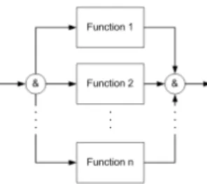
For the modelling of the dataflow, certain elements are necessary to create parallel structures and probabilistic choices of functions, to conduct iterations and loops. To model parallel structures an AND or ”&” is applied at the beginning, where the parallel structure starts and at the end of the parallel structure. The subsequent function of the closing element will not be executed before the last function of the parallel structure is completed. It is possible to implement several subsequent functions, loops, iterations and OR structures [4]. Such a parallel structure is schematically shown in fig. 4. In the same way as the AND structures, the OR structures are modelled. On the contrary to AND elements, the OR elements are choices of probabilistic nature and can also be modelled as a parallel structure. Only one function at once can be executed [4]. Such a choice structure is schematically shown in fig. 5. For this case, the probability that Function 1 will be chosen is: p = 1 − x and for Function
Figure 4: Parallel structure with AND-Element
Figure 5: Choice structure with OR-Element
apply loops (LP). Loops are often used systems. In eFFBD, the loop will be run through infinitely and it can be left with the loop exit element LE, which causes that either a subsequent function will be executed or the data flow corresponding higher system level will be continued. It has also to be mentioned that a loop exit element, embedded in a diagram is framed of an OR structure. [4] In fig. 6 is a loop structure schematically pictured.
Figure 6: Loop structure
4
eFFBD applied on an AOCS
The attitude and orbital control subsystem of a satellite contains the devices to stabilize the satellite and orients it in desired directions during the mission. [8] To determine and control the attitude and orbit of the satellite physical devices are used: sensors, computers and actuators. The outputs of the sensors can also be transmitted via the telemetry channel to a groundstation. It is possible to receive set-values via the telecommand channel and also to operate the actuators due to several reasons such as avoiding collisions with space debris.
4.1
eFFBD of operational mode
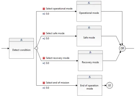
This section is dedicated to the operational layer of the AOCS, which is shown in Fig. 7. The function Detect condition is used to describe the different operational modes: Operational mode, Recovery mode, Safe mode and End of
operation mode. The choice of the exit branch is either done inside of the function which is not decomposed or in a subscenario which is decomposed [2]. This layer of the system affects the functional layer which is described in Sec. 4.2. At the end of the operation, the functional construct is left by an
LE -element.
Figure 7: eFFBD of the operational layer
4.2
eFFBD of attitude control subsystem
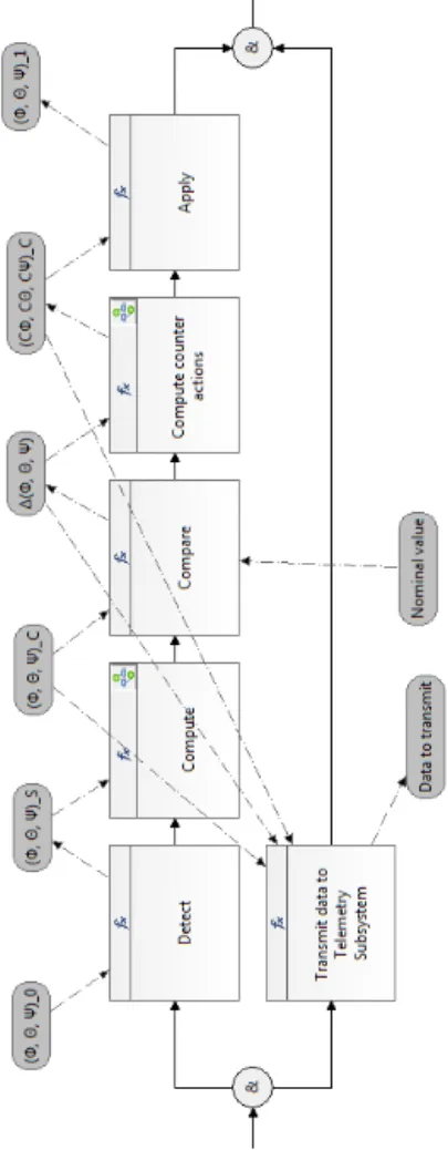
This section is dedicated to the functional layer of the eFFBD of the attitude control system of the AOCS. Fig. 8 shows the eFFBD with its inputs, outputs and dataflows. The eFFBD shows that the process involves generally [7]:
• Measurement of attitude and errors with reespect to external references • Determination of the attitude with respect to the local coordinate system • Computation of commands to correct the error
• Execution of correction
The listing above has been translated into a construct of functions whose labels describe processes inside of the functions.
The functional layer consists of an AND consturct with two parallel branches. The first AND branch describes the control functions whereas the second one represents the communication function. The subsequent branch of the Transmit
data to Telemetry Subsystem function enables the data to transmit, which is
la-beled with Data to transmit. The functional series, which starts with the Detect function represents the steps for the attitude determination, computation of counter actions and application of these counter actions. First the environment is detected by sensors. Then the signal is being processed to compute the atti-tude of the satellite. In the following step the computed attiatti-tude is compared to a nominal value and the result is used to compute commands which will be send to the actuators where they will be applied.
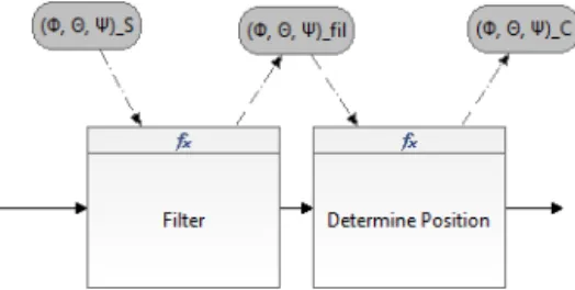
4.2.1 Decomposition of Compute
The function Compute is decomposed in the next lower system layer and pic-tured in fig. 9. It describes the functional series of steps to determine the position. These steps are based on applying techniques of measurement tech-nology and signal processing. The input to this system layer is the output of the
Detect function from the top-layer and are detected angles (Φ, Θ, Ψ)S. These
signals are supposed to be discrete and getting amplified and filtered to remove the noise in the signal. After processing the signal, it can be used to determine the position in orbit, which is applied in the function Determine the position.
Figure 9: eFFBD of decomposed function Compute
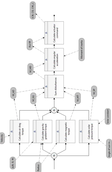
4.2.2 Decomposition of Compute counter actions
The function Compute counter actions computes the angular accelerations of the satellite due to external impacts and calculates counter actions in terms of forces, revolutions, etc are based on the angular accelerations (see: fig. 10).
Additionally to the external influences, like air drag, gravity gradient, Earth’s magnetic field or solar pressure, the inertia of the satellite has to be regarded. First, the resulting disturbing momentums due to the space environment are calculated in parallel branches by using AND elements. The functions are listed right below:
• Calculate air drag torque
• Calculate gravity gradient torque • Calculate magnetic torque • Calculate solar pressure torque
The output results are added in the function Sum disturbances, whose output is the momentum vector ~MDT. This momentum vector is used to calculate
the angular acceleration, which is the output result of the subsequent function. The angular acceleration is the input of the function to calculate the actuator command to counter the disturbances and to move the satellite back to its desired position.
4.2.3 Layered architecture of the AOCS
This chapter is dedicated to the merging of the operational with the functional layer. The resulting eFFBD diagram is shown in fig. 11. In this eFFBD it has been regarded, that the determination of the attitude of the satellite is an iterative process, which has the structure of a loop. The condition to leave the loop is when the end of operational lifetime has been reached. The structure of the loop and loop exit are describe by two LP and one LE element. For the arrangement of the operational and functional layer the hierarchy was taken into account so that the operational order is above the functional layer.
5
Conclusion
The eFFBD systems engineering approach was chosen due to the fact that it describes functions of the system and its order in which they are executed. Hence data dependencies and decision flows between functions can be represented. An overview and description of the eFFBD structural elements are given which are applied to design the AOCS.
It could be shown that it is possible to design the AOCS of a scientific Earth Observation satellite with the eFFBD approach. Processes of keeping the orbit, attitude and the demanded deorbiting at the end of lifetime could be translated into a sequence of functions succesfully. It can be seen as a spin doctor to apply this approach to other subsystems of a satellite and even to their parent system. The data flow can be traced at any time in the diagram as well as in its decomposed functions. The future works are concerning the specifications of the links between each operational mode and some functions in the functional layer.
Figure 11: eFFBD of the layered architecture of the AOCS
References
[1] National Aeronautics and Space Administration: Systems Engineering Handbook, NASA/SP-2007-6105 Rev. 1, 2007
[2] Charlotte Seidner: V´erification des EFFBDs: Model checking en Ing´nierie Syst `me, Doctoral Thesis, Nantes, 2007
[3] St´ephanie Lizy-Destrez: Functional Design: eFFBD modelling, IS548-SDA/eFFBD, Lecture Script, ISAE-SUPAERO, Toulouse
[4] Charlotte Seidner and Olivier H. Roux: On the Formal Verification of
EFFBD Models Using a Structural Translation to Time Petri Nets,
Tech-nical Report RI20073 3695, Nantes,Revised, 2008
[5] Holli Riebeck: Catalogue of Earth Satellite Orbits, last modi-fied: 04.09.2009, Internet, last access: 08.02.2012, 11:55am CET. http://earthobservatory.nasa.gov/Features/OrbitsCatalog/ [6] Domoinique Luzeaux, Jean-Ren´e Ruault and Jean-Luc Wippler: Maitrise
de l’ing´enerie des syst`emes complexes et des systmes des syst`emes,
Lavoisier, Paris, 2011
[7] G´erard Maral and Michel Bousquet: Satellite Communications Systems, John Wiley & Sons Ltd., Chichester, 5th Edition, 2007
[8] Wiley J. Larson: and James R. Wertz Space Mission Analysis and Design, Microcosm, Inc., Torrance, California, 2nd Edition, 1992
[9] Lemai, S., Charmeau, M.-C. and Olive, X. Int´egrer des planificateurs dans le logiciel de vol d’un satellite autonome, JFPDA’06 - Journ´ees Franco-phones Planification, D´ecision, Apprentissage pour la conduite de syst`eme, Toulouse, FR, 2006
[10] Jean-Charles Chaudemar and Eric Bensana and Christel Seguin Model
based safety analysis for an Unmanned Aerial System, 7th IARP Workshop
on Technical Challenges for Dependable Robots in Human Environments (DRHE), Toulouse, FR, June, 2010
A
Table of Acronyms
AOCS - Attitude and orbital control system eFFBD - enhenced functional flow block diagram LEO - Low Earth Orbit
OBC - On-board computer
B
Table of Symbols
Φ - Yaw-angle Θ - Roll-angle Ψ - Pitch-angle