O
pen
A
rchive
T
OULOUSE
A
rchive
O
uverte (
OATAO
)
OATAO is an open access repository that collects the work of Toulouse researchers and
makes it freely available over the web where possible.
This is an author-deposited version published in :
http://oatao.univ-toulouse.fr/
Eprints ID : 12550
To link to this article : DOI :10.1109/IPIN.2013.6817852
URL :
http://dx.doi.org/10.1109/IPIN.2013.6817852
To cite this version : Dalce, Rejane and Van den Bossche, Adrien and
Val, Thierry
Indoor Self-Localization in a WSN, based on Time Of
Flight: Propositions and Demonstrator
. (2013) In: IEEE International
Conference on Indoor Positioning and Indoor Navigation - IPIN 2013,
28 October 2013 - 31 October 2013 (Montbelliard, France).
Any correspondance concerning this service should be sent to the repository
administrator:
[email protected]
Indoor Self-Localization in a WSN, based on Time Of
Flight: Propositions and Demonstrator
Rejane Dalce
Institut de Recherche en Informatique de Toulouse UMR 5505 - CNRS, Université de Toulouse
Toulouse, France [email protected]
Adrien van den Bossche
Institut de Recherche en Informatique de Toulouse UMR 5505 - CNRS, Université de Toulouse
Toulouse, France [email protected]
Thierry Val
Institut de Recherche en Informatique de Toulouse UMR 5505 - CNRS, Université de Toulouse
Toulouse, France [email protected]
Abstract— IEEE 802.15.4 is a widely adopted foundation for the
lower layers of wireless sensor networks. This standard has recently started to take localization into account. This has led to the addition of two new PHY layers, Ultra-Wide Band (UWB) and Chirp Spread Spectrum (CSS), but also the specification of a Time Of Flight-based ranging protocol named Symmetric Double-Sided Two-Way Ranging (SDS-TWR). This paper describes the results obtained from a CSS-based prototype using a variant of SDS-TWR. Our solution differs from others exploiting the same tools by not involving a localization server. The location estimation algorithm is executed by the mobile node, right after the ranging phase. The obtained localization error is generally under 200cm in 90% of the situations and the mean error is around 1m.
Keywords-prototype; demonstrator; localization; positioning; time of flight; wireless sensor network; 802.15.4
I. INTRODUCTION
In every layer of the OSI model, there are protocols and services which could benefit from knowing the current geographical position of the node in a network. Geographical routing in layer 3, content-display application in layer 7 are examples of such possibilities. Their existence has encouraged the scientific community to develop localization solutions which are precise even in areas where the GPS cannot be used, such as an indoor environment. These propositions are often studied through simulations and sometimes using a prototype. In this article, we introduce the results obtained first from a prototype, then from a homemade simulator. We will thus begin with a presentation of the existing testbeds and simulators. We will then discuss the tools used in this study. Finally, we will present and analyze the results obtained from both platforms.
II. RELATED WORK
One of the most efficient ways to prove the feasibility of a proposition is to implement it on a prototype. Depending on the objective, researchers will choose between a prototype with a limited size or a larger version which will often be a public testbed. In the case of Wireless Sensor Networks, a public testbed will consist in a large group of sensor nodes. SensLab [1], for example, provides access to a thousand wireless nodes. Theses hardware modules are shared by various French laboratories. Among those modules, 512 nodes are based on IEEE 802.15.4 Direct Sequence Spread Spectrum (DSSS) and can therefore be used to study WSN related topics.
Harvard University also proposed a testbed named MoteLab [2]. Using this testbed, registered users can upload their solution to TMote Sky nodes, execute their application and retrieve the trace files for further processing. Each one of the 190 TMote Sky nodes is equipped with an IEEE 802.15.4 DSSS transceiver and various sensors (light, temperature…).
Finally, the WiseBed [3] platform uses 313 wireless nodes, some of which are based on the JN5148 from Jennic.
Using these testbeds, it is possible to study issues related to various layers of the OSI model. The most common problem is scalability or how well the proposed solutions behave when the network population grows. In the case or localization, the study of the impact of node mobility and anchor density involves a large network.
Nevertheless, we have not resorted to these structures during our study as the communication technology available on these platforms was not appropriate for localization. The nodes, in our context, must be able to measure Time Of Flight (TOF) and return this information to the MAC layer. The JN5148
from Jennic is one IEEE 802.15.4 platform which offers this possibility. Unfortunately, the underlying radio technology does not support precise ranging. The study presented in [4] shows that DSSS is not suitable for indoor localization.
This article will therefore introduce the prototype used during our study. Results obtained from this platform will be discussed along with data collected from simulations. As mentioned earlier, we used a homemade simulator. The following paragraphs will explain this choice.
There are many network simulators available to the scientific community. Among the free tools, we found WSNet+WSim [1], OMNeT++ [5], NS-2 [6] and NS-3 [7]. We will first introduce the NS family then the WSNet+WSim platform.
NS-2 is a network simulator for which many protocols have been implemented. Although the suitability of NS-2 for the study of WSN-related issues as been questioned, for example in [8], this tool is commonly used when evaluating propositions targeting WSNs. In [11], distance measurement or ranging is performed using RSSI and the impact of noise on the result is modelled by a random normal variable whose mean and standard deviation depend on the real distance. In [9], time-based ranging is implemented and the effect of the environment is modelled by a Gaussian variable with mean equal to zero and 3ns standard deviation. Other error sources are omitted in this study.
The most recent version of NS-2, named NS-3, is as rich as the previous but does not yet fully support the study of WSNs.
MIXIM [11] has spawned from OMNET++. This simulator aims to be the reference tool for the study of both wired and wireless networks. MIXIM includes an implementation of IEEE 802.15.4 DSSS and 802.15.4a [12] UWB. The study in [13] shows the level of detail and the effort to bring this simulator close to results from the real world. In particular, much effort has been put in the design of PHY layer models.
Unfortunately, both NS-2 and OMNET++ do not take the impact of being a wireless sensor node on processing time into account. In the case of NS-2, this particularity has been indicated by the study described in [14]. Regarding OMNET++, this was a deliberate choice, as indicated in [13].
The WorldSens platform [15] combines two simulators: one is WSNet which is a network simulator and the other is WSim [16] which emulates the behaviour of the target sensor nodes. First, the protocol is dimensioned using WSNet. Then, the binary code written for the target nodes is injected into WSim. This simulator is configured to mimic the exact behaviour of the real modules: this is made possible by describing with a high level of detail the various components of the system and its peripherals.
Unfortunately, such a high level of detail can be a drawback: if the target platform cannot be built using the available libraries, one may question the need for this simulator. As far as we know, the ATMega644V and the 802.15.4a CSS technology, which we chose for our study [17], have not been implemented in WorldSens. Simulating our
proposition with this tool would involve selecting an equivalent target which goes against the simulator’s objectives.
These limitations led us to developing our own simulator, DokoSim. This article will introduce this new simulator and compare the results obtained with the performance of our prototype.
III. PROPOSED PROTOCOL AND TEST PLATFORMS We conducted our study in a manner that sets us apart from the usual pattern: using the prototype, we studied localization between one mobile node and a set of anchors placed within the mobile’s radio range. The collected data and the understanding of the real behaviour of the devices were then used to develop a simulator in order to evaluate other solutions. This section will therefore begin with the presentation of the various tools used before introducing the protocols which have been evaluated.
A. Test platforms
1) Prototype
We used the AVRModule from Nanotron [18] as the core of our prototype. These nodes are built using a CSS transceiver which is controlled by the ATMega644V [19]. The transceiver supports 250kb/s communications but must be configured to 1Mb/s in order to use the ranging function. The microcontroller offers 4kB of RAM, 64kB of Flash and communication through a serial port.
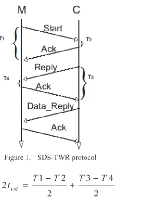
The nodes measure TOF using Symmetric Double-Sided Two-Ray Ranging (SDS-TWR). Figure 1 illustrates the execution of the protocol between a mobile M and an anchor node C. While exchanging messages and acknowledgements, the nodes measure T1, T2, T3 and T4. These durations are combined using (1) in order to obtain the TOF. For M to be able to use this formula, a third data frame, called Data_Reply, must be sent by C which contains T2 and T3.
Figure 1. SDS-TWR protocol 2 4 3 2 2 1 2tvol = T -T + T -T (1) Since the bandwidth of a CSS signal is larger than that of a DSSS signal, the distance measurement becomes more
accurate. Nevertheless, the current implementation relies heavily on the ACK frames to succeed: as a matter of fact, should the ACK frames be eliminated, time stamping would be done using an upper layer clock which has a resolution of 30µs, which would result in a localization error around 10km!
Although our solution does not involve a localization server, a computer is also included in the demo set. Its sole purpose is the execution of a Java application which allows visualization of the results. The mobile node, after estimating its own position, transfers the data to the computer which then displays it and allows the user to log the results and calculate the error.
2) Simulator
The previous section introduced our prototype. In [4], we proposed an innovative protocol for time measurement while eliminating the ACK frames. In order to study it, we developed a simulator named DokoSim. This simulator allows visualization of the interactions between the nodes of a network. We modelled the wireless medium which is responsible for conveying the radio messages from source to destination in a time mostly dependent on the distance. In DokoSim, sending a message equals giving the message to the medium entity which will in turn give the frame to all the nodes involved, depending on the properties of the link between source and each destination. Among these properties, we find the distance but also the frame loss rate. In our implementation, we defined a global error probability which affects all links. According to this model, some of the transmitted messages are not received due to interferences or transmission errors due to the Bit Error Rate. This model is suitable for a simulator which positions itself above the physical layer: while many phenomena can lead to the loss of a message, from the chosen perspective, they will all be accounted for as lost messages. Finally, if the distance between the partners is greater than the maximum configured radio range, the message is not delivered.
Figure 2. Class diagram in DokoSim
A finite loop simulates the flow of time. The durations associated with various phases of the process have been configured using either data collected on the prototype, or theoretical formulae indicated in IEEE 802.15.4.
DokoSim takes broadcast zones as well as collisions and the real duration of frame processing into account. This particular information has been measured on the prototype. As it influences the execution of our protocol, we took it into account. In another study [4], we analyzed the reduction of the duration of various ranging protocols and used this information to improve the credibility of the simulation results.
The impact of multipath is modelled by (2): a Gaussian variable, multipathFactor (MP), represents the additional delay introduced by the environment.
tflight=dist(A,B)/ c + multipathFactor * random [ns]
(2)
Finally, this tool has been developed using the Java language and is based on the class diagram shown in figure 2.
B. Ranging protocol
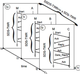
We named our protocol Sequential TWR as the SDS-TWR is executed in turns with each partner anchor. The anchors can be chosen based on the quality on the link between them and the mobile. This quality can be linked to the Received Signal Strength Indication. More generally, it is necessary to negotiate the interval within which the ranging protocol is executed. This process is described in detail in [4]. We will focus here on the ranging protocol. Its execution is shown in figure 3.
Figure 3. Ranging protocol SSDS-TWR
Let A, B, C be the anchors and M the mobile. The mobile executes SDS-TWR with A at t0 then at t1, it measures the
distance between B and itself. Finally, the distance between M and C is evaluated.
The collected measurements are converted to distances and then combined using the inter Ring Localization Algorithm (iRingLA) [4]. This algorithm is executed by the mobile. First, the distance estimation is turned into a ring which represents the area within which the mobile believes itself to be located.
The intersection of these rings is then studied: a matrix in built on the intersection of two rings. Each cell represents a point. The points that do not really belong to the intersection are discarded. The other available rings are used to refine the points. The remaining points are combined in order to generate the estimated position.
A light algorithm has also been described in [4]. It enables the mobile node to select the intersection on which to build the matrix in order to maximize the chances of correction position estimation. This algorithm selects the two smallest rings’ intersection as the area within which the estimated position must be found. Although it was first based in heuristics, this decision algorithm has been verified mathematically in [4]
IV. TEST ENVIRONMENTS AND PERFORMANCE This section will introduce the test environment and the results obtained in each configuration. We will execute SSDS-TWR with 3 anchors, both on the prototype and on the simulator. We will also examine how the value selected for MP influences the results and can therefore be used to simulate a particular environment.
A. Room #1
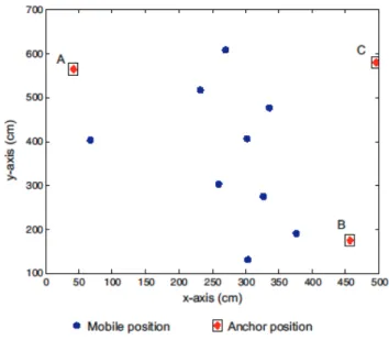
We first conducted experiments in a 6.89 x 8.28 m² room. The nodes were placed on tables (wooden with metallic structure) 0.75m high according to the topology illustrated by figure 4. The position of each anchor is indicated by a diamond in a square. The blue dots represent the positions occupied by the single mobile node during the measurements. The experiment focuses on the star interval [4] which is dedicated to the execution of the ranging protocol. SSDS-TWR is used to sequentially interact with A, B and C. In the end, the mobile combines the data to estimate its position. In each position of the mobile, sixty samples are collected.
Figure 4. Topology used in room #1
1) Prototype results
Figure 5 shows the error repartition. The error intervals are indicated in centimetres. Because of frame losses, the total
number of samples is 1096. Most of the experiments result in a localization error lower than 175cm. The error is under 200cm 96% of the time and the mean error is 100.3cm. In a few situations, the error is greater than 200cm: in these cases, the ring ordering algorithm fails to identify the best location to build the matrix since the real position is not contained in the smallest rings. 30 50 75 100 125 150 175 200 225 250 275 300 0 50 100 150 200 250 300 error interval (cm) n u m b e r o f s a m p le s
Figure 5. Error repartition (room #1)
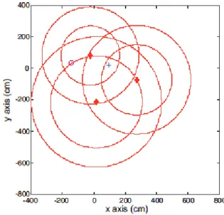
The situation depicted by figure 6 corresponds to the cases where the error is greater than 200cm. The red diamonds represent the anchors, the circle indicates the real location of the mobile and the cross the estimated position. The position was first searched for in the intersection of the smaller rings. In his particular case, the third ring did not manage to filter one of the intersections. The estimated position therefore lies between the two parts of the intersection.
Figure 6. Severe error due to absence from small rings
2) Simulation results
We ran the simulations multiple times in order to determine the value of multipathFactor which matches this environment. We configured it to 7. In this case, the mean localization error is 110cm (under 200cm 89.4% of the time). Figure 7 shows the error repartition. Just as shown in figure 5, most of the errors are between 100 and 150cm and the situations where the error
is greater than 200cm are quite rare. We managed to recreate in simulation, the situation where the smallest rings are not the most accurate. This corresponds to the largest errors.
30 50 75 100 150 200 250 300 350 400 0 50 100 150 200 250 300 350 error intervals (cm) n u m b e r o f s a m p le s
Figure 7. Error repartition from simulations with MP=7
B. Room #2
This room is 6.68 x 5.16 m². Cushioned chairs and tables are mostly found there. The wireless nodes are placed on the tables according to the topology given in figure 8.
Figure 8. Topology used in room #2
For each mobile position, we collected forty samples.
1) Prototype results
In this configuration, the mean error is 96cm (under 200cm 95% of the time). Figure 9 shows that most samples have an error less than 125cm. The error is lower than what was observed in room #1. In this room, there was metallic furniture along the walls at the height of the nodes’ antennae. In room #2, the impact of the environment was reduced as there was no furniture along the walls.
30 50 75 100 125 150 175 200 250 275 300 0 10 20 30 40 50 60 70 80 error intervals (cm) o ccu re n ce s
Figure 9. Error repartition (room #2)
2) Simulation results
We first ran the simulation with MP unchanged. It resulted in a mean error of 135cm (under 200cm 81.6%of the time).
30 50 75 100 150 200 250 300 350 400 0 20 40 60 80 100 120 140 160 error intervals (cm) n u m b e r o f s a m p le s
Figure 10. Error repartition with MP=7 and the topology for room #2 We compared the bar graph from figure 10 with the one obtained from the prototype and noticed that, while on the prototype, the percentage of cases where the error was greater than 200cm was 4.5%, in the simulator, it represented 18.33% of the cases. This shifts the error toward greater values. In order to reduce the difference between prototype and simulation, we set the multipathFactor to 5. Under this configuration, we obtained a mean error of 95cm. As shown in figure 11, the localization error is lower than 200cm in 94% of the cases. The change in configuration has effectively brought the simulator closer to reality.
30 50 75 100 150 200 250 300 350 400 0 20 40 60 80 100 120 140 error intervals (cm) n u m b e r o f s a m p le s
V. CONCLUSION AND PERSPECTIVES
In this article, we described a prototype based on the CSS technology, which is capable of measuring TOF. The ranging protocol SDS-TWR is executed sequentially with various anchors, 3 in our case. We also introduced our simulator, DokoSim, which is used to evaluate both the protocol and the algorithm. The results obtained from both prototype and simulation show a mean localization error around 1m. In all cases, the error is lower than 200cm 90% of the time. We provided our simulator with parameters that help bring its results closer to reality by altering the effect of the environment on the measurements. In the near future, we plan to study the integration of localisation in the network organization. Although this study can be conducted easily using DokoSim, it would be more challenging to implement our solution on a real public testbed offering TOF-based ranging capabilities.
In addition, we have proposed other ranging protocols which have been studied using DokoSim. We are now working towards implementing these protocols on a new UWB-based prototype.
REFERENCES [1] http://www.senslab.info/ (Accessed May 2013) [2] http://motelab.eecs.harvard.edu/ (Accessed May 2013) [3] www.wisebed.eu (Accessed May 2013)
[4] R. Dalce, Localization methods using the communication signal in indoor wireless sensor networks, thesis, INSA de Toulouse, 2013 [5] OMNET++ http://www.omnetpp.org/doc/omnetpp/manual/usman.html
(Accès janvier 2013)
[6] NS-2 http://www.isi.edu/nsnam/ns/ (Accessed January 2013)
[7] NS-3 http://www.nsnam.org/docs/release/3.16/manual/ns-3-manual.pdf (Accessed January 2013)
[8] Y. Xue, H. S. Lee, M. Yang, P. Kumarawadu, H. H. Ghenniwa, W. Shen, “Performance evaluation of NS-2 Simulator for Wireless Sensor Networks”, Electrical and Computer Engineering, 2007.
[9] A.M. Abu-Mahfouz,G.P. Hancke, "NS-2 extension to simulate localization system in wireless sensor networks", AFRICON 2011 [10] S. Park, H. Ahn, and W. Yu, "A Simple Object Tracking System Using
ITDOA without Time Synchronization", ICACT 2007 [11] http://mixim.sourceforge.net/ (Accessed May 2013)
[12] Specific requirements Part 15.4: Wireless MAC and PHY Specifications for Low-Rate Wireless Personal Area Networks (WPANs) Amendment 1: Add Alternate PHYs, IEEE Standard for Information technology Telecommunications and information exchange between systems, 2007 [13] J. Rousselot, M. Aoun, R. Serna Oliver, « Accurate Timeliness
Simulations for Real-Time Wireless Sensor Networks », Computer Modeling and Simulaton 2009
[14] R. Dalce, A. van den Bossche, T. Val. Optimization of a CSMA/CA based MAC protocol designed for confined WSNs, ICWCUCA, Clermont-Ferrand, France, 2012
[15] G. Chelius, A. Fraboulet, E. Fleury, "WorldSens: a Fast and Accurate Development Framework for Sensor Network Applications", SAC'07, 2007
[16] http://wsim.gforge.inria.fr/ (Accessed May 2013)
[17] R. Dalce, A. Van den Bossche, T. Val. Une plateforme de prototypage évolutive pour la localisation dans un réseau IEEE 802.15.4a CSS, conférence Internationale Francophone d'Automatique (CIFA 2012), Grenoble, 2012.
[18] http://www.nanotron.com/EN/pdf/Factsheet_nanoLOC-AVR-Module.pdf (Accessed December 2011)