SAMTECH’s SOFTWARES : From optimization of very
large composite aircrafts to detailed damage in
composite structures analysis
SAMTECH 软件:从飞机结构中复合材料板的大规模优化
设计到细节结构的损伤分析
MU Quanchen1, REMOUCHAMPS Alain2, BRUYNEEL Mickael2
1SAMTECH Asia Pacific, Beijing, RPC CHINA
2SAMTECH HQ, Liege, Belgium
Abstract
This paper presents the hottest industrial trends in the field of pre-sizing design phase of composite structures and the solution procedures available in the commercial finite element software SAMCEF linked to optimization platform BOSS Quattro. These solutions cover from the global pre-sizing of large composite structure to advanced local studies including delamination and cracks growth. In this paper, three examples driven with industrial partners are described.
摘要:
本文中介绍了当前最热门的趋势,即在工业领域的预先设计阶段中,复合材料
的结构设计和解决方案可以在商业有限元软件 SAMCEF 与 BOSS Quattro 相结
合的优化平台上来实现。这些解决方案,覆盖了从大规模复合材料结构的预先 设计到高级的局部细节的研究,其中包括分层和裂缝增长。此外,本文中的三 个例子都来自于工业合作伙伴的描述。 作者简介 ANTHONY CHERUET 公司:SAMTECH 职位:高级工程师
1. Introduction
Over the last decade, aircrafts manufacturer have driven a significant increasing in the use of composite material because of requirements of reduction on operation costs and fuel emission linked to weight and performance targets.
The introduction of composite material offers additional freedom to design the structure and in the same time, achieving an optimum usage of composites materials requires exploration of larger and more complex design space. As a consequence, the
demand for powerful and efficient design tools increases and brings more and more challenging projects.
The Samtech Company who is the European leading provider of simulation software
for Finite Element Analysis (Samcef software [1]) and Optimisation (BOSS-Quattro [2]) proposes advanced solutions for the hottest current industrial demands of the aircraft industry for composites materials usage. This paper gives an example of three case studies performed with industrial partners.
2. New trends in aeronautical industry
The introduction of composite materials has generated new needs in order to decrease the design stage of composite structure. These needs call the use of optimization methods to assist the down selection of optimum materials and laminates and also advanced methods such as damage analysis to go further in the research of the best design as soon as possible in the design phase. These demands can be classified as follows and are illustrated on figure 1:
¾ Need to provide an integrated analysis and optimization capability to assist
pre-sizing studies for optimum composite box covers design.
¾ Optimization of composite fuselage reinforced panels for buckling (Linear) and post-buckling (Non-linear) analyses.
¾ Damage analysis of laminated structure to study the propagation of craks inside the plies. This latter can also be performed inside an optimization loop. For these three trends, ie from global pre-sizing to advanced local design, the
SAMTECH Company is able to propose performing solutions adapted to the needs
Figure 1 : New trends in Aeronautical Industry
图1:航空工业的新趋势
3. Optimum pre-sizing of Composite Aircraft Box
structures- Global-local structural distributed
optimization
3.1 Introduction
COMBOX is a software application developed by SAMTECH, in a CAESAM software framework [3], to provide Airbus with an integrated analysis and optimization capability to assist pre-sizing studies for optimum composite box covers design ([4] and figure 2).
The analysis process in COMBOX integrates NASTRAN analysis for internal loads calculations with internal Airbus methods for composite stiffened panel analysis. A coupled design sensitivity analysis for internal loads versus composite buckling and strength analysis has been implemented in order to allow the COMBOX optimization process to control buckling and strength reserve factors via both local design changes and by driving internal load changes.
The optimization process in COMBOX was implemented in BOSS Quattro and optimized a full composite cover as one component, by adjusting local composite stiffened panel designs. Design variables that can be adjusted include skin thickness and skin laminate percentages as well as stringer cross-section dimensions. COMBOX is today a working tool capable of handling full component analysis and optimization adjusting in the order of 1500-2000 design variables whilst monitoring a dynamically updated constraint set with up to 100000 near active constraints.
图2:COMBOX 用户界面
3.2 Formulation of the problem
The structural analysis process implemented in COMBOX integrates global finite element analysis for internal loads calculation (using MSC/NASTRAN) with local composite stiffened panel buckling and strength analyses being performed using internal Airbus methods and tools, the internal loads being the input of the local analysis tools.
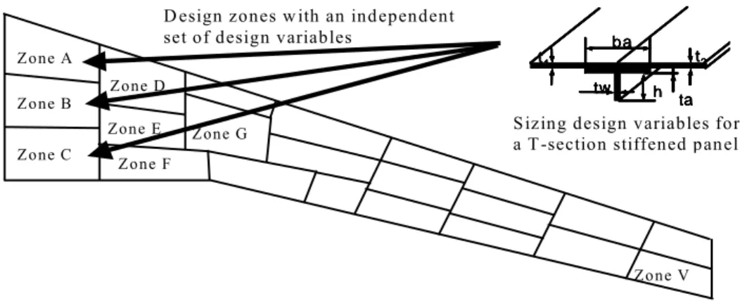
The design variables are physical properties of the panels (thicknesses) and stiffeners (section profile). Additional design variables are controlling the orientation of the composite plies. They are applied by zones (regions) on the structure and they are inputs for both the global finite element analysis and the local analysis.
D esign zones w ith an independent set of design variables
Zone A Zone B Zone C Zone D Zone E Zone F Zone G Zone V h b a ta tw t2 t1 h b a ta tw t2 t1 h b a ta tw t2 t1 h b a ta tw t2 t1 h b a ta tw t2 t1
Sizing design variables for a T-section stiffened panel
Figure 3 : Design variables regionalization
图3:设计变量区分
The objective is, of course, the reduction of the mass (computed by NASTRAN).
The design constrains ("Reserve Factors") are obtained from the local analyses ("Skill
Tools” on "Computation Points") and can be classified as follows :
¾ Buckling analysis
¾ Damage tolerance analysis ¾ Reparability analysis
¾ Design rules (aspect ratios, …)
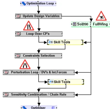
All these constrains are computed for several load cases. The optimization process is then automatically generated in BOSS Quattro, ensuring the appropriate process dependencies and data flow (Figure 4).
Figure 4 : BOSS Quattro optimization loop over Analysis chain 图4:BOSS Quattro 优化分析循环链
3.3 Sensitivity analysis and optimization solution
Gradient based techniques with local approximation schemes (Conlin, Fleury and Braibant [5], and GCM, Bruyneel [6]) are used to solve iteratively the design problem. The required sensitivities of the local analysis results (RF's) are a combination of a direct term and another one, due to the influence of the design variables DV on the global model internal forces that feed the local analyses :
Global Local DV Forces Forces RF DV RF dDV dRF ∂ ∂ ∂ ∂ + ∂ ∂ =
The evaluation of the internal forces derivatives is performed by NASTRAN Sol200 and the local derivatives are obtained with a finite difference scheme. Once available, they are recombined by BOSS Quattro following a chain rule. Due to the (large) size of the problem (1000 design variables, 300000 constraints), an appropriate methodology has been implemented to tackle with performance issues (computation time and memory needs). Basically, the goal is to decrease the problem size, the amount of computations and to reduce the overall process time by using in parallel computer resources distributed over the network.
3.3.1 Problem reduction: constraint filtering
Several controls were introduced in order to let the user define the rules to unselect constraints that are far enough from their critical bound: these constraints are ignored by the optimization process during a limited number of iterations. A frequency is set, where the selected constraints set is re-evaluated, in order to (re)introduce constraints and/or remove some others. This technique has two major benefits:
Decrease the optimization problem size sent to the optimizer (Conlin and GCM) and, therefore, save computation time and memory needs.
Reduce the number of computations requested during the sensitivity analysis performed by finite-differences.
3.3.2 Performance issues: distributed computing In order to speed-up the overall optimization
process, several levels of the overall COMBOX process have been parallelized. The idea was to break the bottleneck caused by the sequential loops:
NASTRAN/Sol200: the loop over load-cases is split onto several sub-loops. The benefits from splitting the overall Nastran/Sol200 job into several sub-jobs are double. First, it reduces the overall cycle time. Second, by reducing the number of load cases, memory needs are also reduced, allowing larger jobs to be run on a given computer.
Local (skill tools) analysis: here, many small computations have to be done, for both simple function evaluations and finite-difference sensitivity analysis. Parallelization then becomes natural. In order to marginalize the
fixed costs, COMBOX regroups analysis work into sizable packets performing several skill tool analysis calls together in a “burst Computing”.
All these analysis tasks are distributed and managed by BOSS Quattro on the network. On Airbus sites, an LSF infrastructure has been used.
Figure 5 : BOSS Quattro Distributed Computing Implementation 图5:BOSS Quattro 分布式并行计算
3.4 Airbus application
The following example illustrates the use of COMBOX in an A350 XWB wing covers pre-sizing study (figure 9). The optimization study has been defined as an optimization problem with fixed laminate percentages and fixed laminate orientation, so it is a sizing optimization study. The top and bottom wing cover has been
parameterized, defining constant property design regions that are 2 stringer bays wide and 2 rib bays long.
Figure 6 : Wing cover design parameterisation for pre-sizing study
图6:机翼预先设计阶段时的结构参数化
3.4.1 Problem definition
In the present study only a subset of the possible design variables were selected. The set of active design variables was:
¾ Skin thickness (t) ¾ Stringer height (h)
¾ Stringer angle thickness (ta)
The set of constraints included in the present study were limited to include: ¾ Buckling Constraints:
o Local Stringer Buckling (RF > 1.0) o Local Skin Buckling (RF > 1.0) o Global Buckling (RF > 1.0) o Damage Tolerance Constraints: o Skin Damage Tolerance (RF > 1.0) o Stringer Damage Tolerance (RF > 1.0) ¾ Reparability Constraints:
o Skin Reparability (RF > 1.0) ¾ Design Rules Constraints:
o Skin Area / Stringer Area Ratio (0.4 -1.2)
The optimization was performed considering a pre-selected set of load cases consisting of 20 critical flight and ground cases. All load cases were applied as ultimate cases and constraints were in all cases imposed requiring strength and buckling reserve factors to be larger than 1.0 at ultimate load.
3.4.2 Results: Convergence
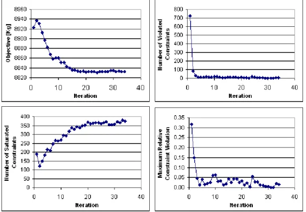
The defined optimization problem was run using the GCM optimizer. Next figure shows convergence history plots for the objective function (weight), number of violated constraints, number of saturated constraints and finally for the maximum
relative constraint violation. These plots are essential to assess the overall convergence (figure 7).
Figure 7 : Convergence history plots for wing pre-sizing study
图7:机翼预先设计研究的收敛历程图
In the present example the optimization problem has been started from a near feasible solution, and thus the objective function history only shows a small overall weight reduction. At the starting point the design has a total of almost 700 violated constraints. The number of violated constraints is rapidly reduced to only a few violated constraints in iteration 4. At the same time the number of saturated constraints is steadily increasing to approximately 375 active constrains at iteration 20 onwards. The final convergence graph provided here shows the maximum constrain violation, which is rapidly reduce to below 5 percent from iteration 4 onward. An acceptably converged engineering solution may be seen to have been obtained from iteration 20 onwards.
3.4.3 Results: Plots
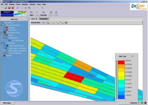
Whereas the convergence graphs for the objective function and the constraint (violation and activation) provide a good overall indication of the overall convergence of the optimization process they give very little information about the quality of the solution.
To assess the quality of the optimization solution it is necessary first to look at the design description. Design variable plots showing the distribution of individual design variables across the wing can highlight flaws in the optimization problem formulation.
Figure 8 : COMBOX Post Processing 图8:COMBOX 后处理
Several plots are available in COMBOX, allowing displaying design variables, constraints and envelopes (figure 8). Additional outputs are also used by Airbus with their own formalism.
4. Optimization of composite structure like composite
fuselage panels
4.1 Introduction
The optimization of composite panels is a big challenge due to the inherent complexity of the analysis methods involved in the computational process and the type of responses required by the formulation of the optimization problems to be solved.
The originality of the last developments integrated in SAMTECH’s products is that the optimization problem can be solved by combining linear and nonlinear finite element analyses in the same computational framework where the evaluation of semi-analytical sensitivities allows huge time savings with respect to e.g. finite-differences schemes.
4.2 Definition of the problem involving composite structure
A classical formulation of optimization for composite structure can be :
¾ Design variables can be composite ply thicknesses, profile stiffener design or plies orientation;
¾ The objective function is the mass of the considered composite structure that must be minimized
¾ Some constraints must be also defined, for example for composite fuselage panels :
o Linear buckling reserve factor: RFbuckling ≥1,
o Collapse (non-linear post-buckling) reserve factor: RFcollapse ≥1.
Figure 9 : Definition of the model for the fuselage panel
图9:机身壁板的模型定义
For the linear buckling optimization aspects, the importance of selecting enough buckling modes must be explained. In particular, a small value for this number (say
12 =
n ) may be insufficient in the sense that at some iterations those n buckling modes may only influence a small part of the structure, which will be designed, while the remaining structural parts are not sensitive. The panel thickness in the sensitive part could increase to satisfy the stability criteria, while the thickness in the insensitive part will certainly reach its lower bound, since it is to be minimized. At the next iteration, the low-thickness part is likely to become sensitive to buckling because of a small local stiffness, while the remaining part could become insensitive to the restrictions. If repeated, this scenario leads to oscillations and deteriorates the convergence of the optimization process. For industrial example, we found that using
100 =
n leads much better results. The linear buckling computation is performed by the STABI modulus of the Linear finite element software package.
The nonlinear finite element analysis and the computation of the collapse reserve factor and its sensitivities is performed by SAMCEF Mecano, a finite element
software package that solves nonlinear structural and mechanical problems. The two objectives are :
¾ find a suitable way to compute the result on the basis of results provided by the nonlinear analysis;
¾ ensure that the sensitivities of the result (with respect to all design variables) may be computed.
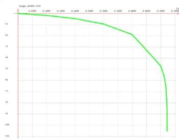
An obvious choice for the collapse RF is the load factor, which we denote by λ in the sequel. As an illustration, let us consider a simple super stiffener subject to both compression and shear loads. Assume that loads are applied progressively, the full loads (100%) corresponding to time 1. The nonlinear analysis terminates at time
t ≈ 0.566 (that is largely before the full loads are applied) because time steps become
too small. This means that for the given value of design variables only 56.6% of the loads can be applied before collapse occurs. In this case we could thus have taken
566 . 0 ≈ = = t RFcollapse λ .
The picture of Figure 10 shows the displacement of a node (belonging to the skin panel of the super-stiffener) along the z-axis.
Figure 10: Displacement of a node as an illustration of the collapse.
图10:节点位移结果的例子
However this way to compute the collapse RF is not fully satisfactory since the sensitivity of λ is not directly available from a nonlinear analysis.
This is why we have chosen to derive such a sensitivity using another method for the nonlinear analysis, namely Riks’ continuation method [7]: while classical Newton methods can have problems when passing a limit-point (because the generalized load displacement curve may have a decreasing time along the curve), continuation methods (also called arc-length or Riks methods) involve an additional parameter, namely the arc length, which is controlled instead of the time. This was combined with the implementation of a dedicated computational mechanism ensuring that the gap Δλ is orthogonal to the curve (rather than vertical) which further improves the accuracy of the sensitivity.
Altogether, this methodology allowed us to derive a suitable algorithmic process for computing the value of the reserve factor and its sensitivity. This process was successfully implemented within SAMCEF Mecano and tested on a variety of examples.
Then, building the optimization session is straightforward:
¾ Definition of a parameterized model that includes the definition of the composite material properties
¾ The optimization variables are selected from the list of the parameters used in the definition of the model
¾ The complete computational process is then created, involving as many external tasks as the number of analyses
¾ The external tasks are connected to the optimization task: both the type of function (objective to be minimized, inequality constraint…) and possible associated bound may be selected and also the admissible thresholds, the maximum number of iterations….
4.3 Industrial applications
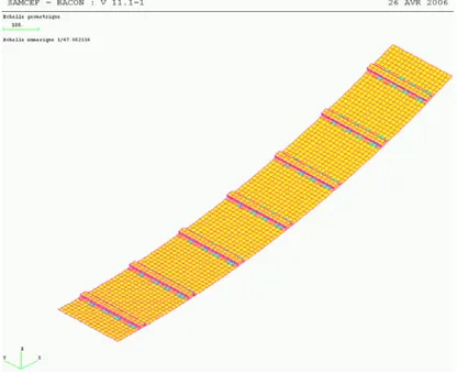
The developments described above were tested on a real test case from Airbus [8]. The aim is to perform the optimization of a composite panel made of seven super-stringers, as illustrated on Figures 9 and 11. The considered stringers have a trapezoidal profile – they are also called Omega stringers.
Figure 11: SAMCEF model for test case. 图11:针对测试的 SAMCEF 模型
The corresponding finite element model was built with SAMCEF. This model has 17326 nodes, 16000 cells and 109777 degrees of freedom. Design variables are ply thicknesses for each ply orientation (0º, 45º and 90º), for each one of the seven super-stringers. A distinction is made between thicknesses for skin panels and for super-stringers. This amounts to considering 3 x 7 x 2 = 42 design variables. In the sequel, we denote them as follows:
¾ for the skin panels: SKINi angle
t , , with i∈
{
1,...,7}
and angle = 0º, 45º or 90º;¾ for the stringers: STRINGERi angle
Lower and upper bounds on these variables are set to 0.4 and 2 respectively. The objective function and the restrictions (reserve factors) are equivalent to those defined in Section 2.1 above.
This optimization problem was implemented in BOSS Quattro as described before. The optimization run converged properly after 27 iterations – which is remarkably fast given the complexity of the model and the associated analyses – and yielded a 35% reduction of the mass.
The pictures of Figure 12 show the evolution of all three functions defining the optimization process (mass, buckling and collapse reserve factors) and the associated deflections: the left pictures of the panel show displacements corresponding to the first buckling load while the right pictures show displacements at collapse. Note that the lowest weight value was obtained at iteration 15 but this did not correspond to a feasible solution (the buckling reserve factor constraint is violated).
Figure 12 : Results of composite panel optimization
图12:复合材料板的优化结果
5. Damage analysis and study of propagation of
cracks
With their high stiffness to weight ratio and their anisotropic properties, composite materials are widely used in the aeronautics industry. One of the predominant modes of failure in laminated composites is delamination, resulting from a separation of adjacent layers at locations sensitive to transverse effects (Figure 13).
Figure 13 : The three fracture modes and the inter-laminar toughness
图13:三种断裂失效模式以及层间韧性
A large amount of cracks can initiate in real-life laminated structures and weaken their overall mechanical properties. It is therefore mandatory to take those defects into account in the design phase and to check the structural integrity while they propagate. Hence assessing the damage tolerance of composite structures is clearly a challenge. At least two numerical approaches have been developed to study delamination with the finite element method [9] and are now available in SAMTECH’s products.
The first one consists in using fracture mechanics in a (possible) linear static analysis and to compute the strain energy release rates by mode along the different crack fronts (Figure 1) in order to evaluate the most dangerous crack [10], [11]. By comparing the computed values of the modes of the energy release rate GI, GII and GIII to the
inter-laminar fracture toughness GIC, GIIC and GIIIC, via some criteria, propagation risks can
be assessed and the related propagation load can be estimated (figure 14). In Samcef, the VCE method (Virtual Cracks Extension) has been implemented and gives very accurate results.
The second one, in a more advanced non linear analysis, consists in simulating cracks growth by inserting cohesive elements at some interfaces between plies, where a specific non linear softening law is assigned to the material of this thin layer, and its stiffness and strength can decrease and become equal to zero over the loading, simulating a decohesion between the plies ([12], [13], [14], [15] and figure 15).
Figure 14 : Estimating the danger from a crack in a composite structure.
图14:对复合材料结构中裂纹损伤的评估
Modelling and solving such a finite element problem is difficult. An efficient numerical solution procedure should be able to easily insert multiple crack fronts in a given large scale meshed structure, and to efficiently manage not only softening material behaviours assigned to the interfaces, but also the numerous contacts that can appear between the plies. It results that most of the published works in the field present solutions for simple composite structures with a small amount of delamination sites and few contact conditions.
For solving industrial problems a finite element software code should be able to model multi-delaminated composite structures with a very large amount of cracks and to provide quickly an accurate solution. Such a quick solution can be obtained by considering medium size models with adapted material law parameters. For large to very large size problems, an efficient parallel solution procedure should be used.
Figure 15 : Estimating the propagation of the inter-laminar damage with the cohesive elements approach
图15:采用粘结单元方法模拟的层间损伤传播的评估
5.2 The principle of the Virtual Crack Extension method
In SAMCEF, the VCE method is implemented in order to extract the three modes of the energy release rate GI, GII and GIII corresponding to the three different crack
solicitations illustrated in Figure 1. In this technique one computes the variation of the total potential energy π with respect to a given crack surface increment dA. This provides the total energy release rate GT, which is a measure of the way the stiffness is
dropped when a crack propagates. This total energy release rate is the sum of GI, GII
and GIII depicted in Figure 1. Then the contribution to the three individual modes are
measured, based on the relative movements of the lips during the loading and on the reactions against the crack propagation (forces at the crack tips necessary to keep the crack with its current length although an external action tends to make it grow). The principle is illustrated in Figure 16. It is important to note that only one structural analysis is necessary to compute GI, GII and GIII with this technique. The method is
available for problem including geometric non linearities, and is being extended to non linear elastic material behaviours. An example of application is detailed in [16] where the VCE method of SAMCEF is successfully applied to a complex laminated structure.
Figure 16 : . Principle of the VCE method of SAMCEF 图16:SAMCEF 中 VCE 方法的原理
5.3 The principle of the cohesive elements approach
In order to model the possible inter-laminar damage, a thin layer may be inserted between two plies of the composite, as depicted in Figure 17. A specific non linear softening law is assigned to the material of this thin layer, and its stiffness and strength can decrease and become equal to zero over the loading, simulating a decohesion between the plies.
The approach presented in [12] is available in SAMCEF. The constitutive polynomial softening material law proposed in [12] is depicted in Figure 6a. In SAMCEF it has been extended to a bi-triangular and an exponential laws. The whole set of available constitutive laws for delamination is provided in Figure 6. For the polynomial and bi-triangular cases, the damage appears after a threshold defined by the user (represented by the green regions). For the exponential law, the damage directly appears when the interface is loaded.
Figure 17 : Inserting an interface element between two plies of a composite. Illustration of the interface behaviour under loading
图17:复合材料层间插入界面单元,图中阐述了界面单元在载荷下的特性
According to the softening material law and since large displacements can appear, a non linear static solution procedure is used. Looking at a typical load-displacement curve (as in Figure 15), passing over the maximum may be difficult since a lot of energy may be suddenly released. To ease this transition, several strategies are available in SAMCEF, as using the polynomial or exponential laws of Figure 18 (which do not present a too rough discontinuity between the un-damaged and damaged behaviours), or selecting a small delay in the damage occurrence. Besides, dynamic solution schemes with damping can be a work-around.
Figure 18 : The constitutive softening laws available in SAMCEF for the interface elements
5.4 Illustration on DCB and ENF specimens
5.4.1 The Double Cantilever Beam (DCB) and End Notched Flexure (ENF) tests
Those standardised tests are illustrated in Figure 19 and are often used as benchmarks in numerical applications [17].
Figure 19 : Illustration of the DCB and ENF tests 图19:DCB 和 ENF 试验
5.4.2 The Double Cantilever Beam test solved with the VCE approach
Three stacking sequences including 32 plies are tested, according to [17]. A load at the beam tips opens the crack lips. Only mode I is active (Figure 13). The results are in very good agreement with the literature. The mesh is refined at the crack front location with an element length le = 0.5mm.
¾ Unidirectional laminate: [016/d/016] , where d defines the crack plane position;
¾ Layup D[++30]: [±30/0/-30/0/30/04/30/0/-30/0/-30/30/d]S;
Figure 20 : The model of the DCB specimen, the displacements for the UD32 laminate and the energy release rates for mode I (GI)
图20:DCB 模型,UD32 层的位移和模式 I(GI)下的能量释放率
5.4.3 The Double Cantilever Beam test: cohesive elements approach
In this application the mesh is refined at the crack location and the element length is le
= 1mm. The load-displacement curves provided in Figure 21 compare results obtained with the three available constitutive laws for the interface (Figure 18). The solutions are very close to the analytical reference. The parameters of those laws should be updated with respect to the analytical solution or the experimental results in order to get a precise description of the interface behaviour, later used in more complex delaminated structures. When available properties of interface with specific fibres orientations should be used to be closer to reality.
Figure 21 : Load-displacement curves in the DCB problem for the 3 different constitutive laws available in SAMCEF
图21:SAMCEF 中 3 中不同定制法则下 DCB 问题的载荷-位移曲线
5.5 Application to complex (industrial) cases
5.5.1 Application of the Virtual Crack Extension method of SAMCEF
The structure is illustrated in Figure 22. It includes a flat skin made of 8 plies, a cap made of 4 plies and a T-stiffener with 8 plies. The boundary conditions are
represented in the Figure. The flanges of the stiffener are built up with 4 plies. Different stacking sequences are used to build the laminate, and include 0°, 45°, -45° and 90° orientations. The base material is graphite-epoxy C12K/R6376. Several cracks are defined over the whole length of the specimen and a total of 9 crack fronts are considered in the fracture mechanics computations. The model includes 663373 degrees of freedom, 56720 volume elements and 4153 contact elements.
100 40 Existing crack Existing cracks Cap (4 plies) Skin (8 plies) Imposed load
Flange- left part (4 plies)
Location of the cracks
Figure 22 : Definition of the problem solved with the VCE approach
图22:采用 VCF 方法求解的问题定义
The results are reported in Figure 23. The evolutions of the energy release rate by mode inserted in a linear fracture criterion are plotted. A crack will propagate when the value of the criterion is equal to 1. It is seen that in our problem cracks 2 and 3 are the most critical ones. Note that here a linear static solution procedure is used. This strategy allows providing a fast estimation of the propagation load.
Figure 23 : Evolution of GI/GIC + GII/GIIC + GIII/GIIIC over the crack fronts of all the cracks 图23:不同裂纹前端模式的裂纹扩展(GI/GIC + GII/GIIC + GIII/GIIIC)
5.5.2 Application of the cohesive elements approach of SAMCEF The structure illustrated in Figure 24 is considered. It includes a flat skin made of 9 plies, a cap made of 4 plies and a T-stiffener with 8 plies. The extremities are clamped. The flanges are made of 4 plies. Different stacking sequences are used to build the laminate, and include 0°, 45°, -45° and 90° orientations. The base material is graphite-epoxy C12K/R6376. A large amount of cracks are defined in the middle of the structure, all over the thickness, and at the junction between the cap and the noodle. Lateral cracks are also defined on the whole specimen length at the edges between the cap and the flanges. The model includes 57 cracks, 293332 degrees of freedom, 19136 volume elements, 1221 contact elements and 12536 interface elements. The bi-triangular law of Figure 18 is used.
80 50 Existing crack Existing cracks Cap (4 plies) Skin (9 plies) Imposed displacement
Flange- left part (4 plies)
Clamp
Clamped
Location of the cracks
Figure 24 : Definition of the problem solved with the cohesive elements approach
图24:采用粘结单元方法求解的问题定义
The load-displacement curve, the displacements and the damage propagation over the loading are provided in Figures 25 to 27. The damage clearly initiates at the junction between the flanges and the noodle. Afterwards it begins to appear at the edges between the cap and the flange. Some interfaces at the clamping location then start to be damaged. Once the energy is released after the maximum load, the damage propagates from the noodle at the interface between the cap and the flanges, to lead to the final failure when the loaded part and the fixations are no longer connected due to a global decohesion. To the expend of a non linear analysis this strategy allows to estimate not only the propagation load, but also the maximum load and the residual stiffness in the fracture process.
Figure 25 : Load-displacement curve for the problem of Figure 24
图25:图 24 问题的载荷-位移曲线
Figure 26 : Evolution of the displacement over the loading (deformed amplification = 3)
图26:载荷作用下的位移变化(变形放大系数=3)
Figure 27 : Location of the damage comprised between 95% and 100% over the loading
图27:损伤位置,包含在 95%和 100%过载之间
6. Conclusion
This paper shows several composite structure design techniques, suitable for optimization of large parts of airplane, for optimization of intermediate parts of plane such reinforced panels and for analysis of delamination and cracks propagation in composite structures.
7. References
[1] SAMCEF . http://www.samcef.com/en/pss.php?ID=71&W=products [2] BOSS quattro. http://www.samcef.com/en/pss.php?ID=3&W=products [3] CAESAM. http://www.samcef.com/en/pss.php?ID=49&W=products
[4] Krog L., Bruyneel M., Remouchamps A. and Fleury C. COMBOX: a distributed computing process for optimum pre-sizing of composite aircraft box structures, 10th
SAMTECH Users Conference,
Liège, March 2007.
[5] Fleury C. and Braibant V. Structural optimization: a new dual method using mixed variables, Int. J.
Num. Meth. Engng., 1986, 23, 409–428.
[6] Bruyneel M. A general and effective approach for the optimal design of fiber reinforced composite structures, Composites Science & Technology, 2006, 66, 1303-1314.
[7] Riks E., Rankin C. and Brogan F. On the solution of mode jumping phenomena in thin walled shell structures. Comp. Meth. Appl. Mech. Engng., 1996, 136, 59-92.
[8] Colson B., Bruyneel M., Grihon S., Jetteur Ph., Morelle P., Remouchamps A. Composite panel optimization with nonlinear finite-element analysis and semi-analytical sensitivities. NAFEMS
Seminar on “Simulating Composite Materials and Structures”, Bad-Kissingen, 6-7 November
2007.
[9] P.P. Camanho. Finite element modelling of fracture in composites: current status and future developments, NAFEMS Seminar – Prediction and Modelling of Failure Using FEA, May 31 – June 1, 2006, Roskilde, Denmark.
[10] R. Krueger. Computational fracture mechanics for composites – State of the art and challenges,
NAFEMS Seminar – Prediction and Modelling of Failure Using FEA, May 31 – June 1, 2006,
Copenhagen/Roskilde, Denmark.
[11] R. Krueger. Virtual Crack Closure Technique: history, approach and applications. Applied Mechanics Reviews, 57:109-143, 2004.
[12] P. Ladevèze, O. Allix, B. Douchin and D. Lévêque. A computational method for damage intensity prediction in a laminated composite structure, Computational Mechanics – New Trends and
Applications (Idelsohn S., Oñate E. and Dvorkin E., eds.), CIMNE, Barcelona, Spain, 1998.
[13] V.Q. Bui, E. Maréchal and H. Nguyen Dang. Imperfect interlaminar interfaces in laminated composites : delamination with the R-curve effect. Composites Science & Technology, 60:2619-2630, 2000.
[14] A. Pantano and R.C. Averill. Finite element interface technology for modelling delamination growth in composite structures. AIAA Journal, 42:1252-1260, 2004.
[15] P. Camanho, C.G. Davila and D.R. Ambur. Numerical simulation of delamination growth in composite materials. NASA-TP-211041, 2001.
[16] P. Thévenet. Tolérance aux dommages des structures aéronautiques – Délaminage dans les stratifiés monolithiques et flambage des structures minces. 10th
SAMTECH Users Conference, Palais
des Congrès, Liège, March 13-14, 2007.
[17] R. Krueger. Three dimensional finite element analysis of multidirectional composites DCB, SLB and ENF specimens. ISD-Report N° 94/2, Institute for Statics and Dynamics of Aerospace Structures, University of Stuttgart, Germany,1994.