C. Adam, R. Heuer, W. Lenhardt & C. Schranz (eds) 28-30 August 2013, Vienna, Austria Paper No. 241
Abstract. This paper presents an overall summary of a running research project aiming at the validation of structural solutions using unreinforced load-bearing clay masonry for family houses and multi-storey buildings fulfilling the requirements of Eurocode 8 for low to moderate seismic areas. The paper covers the following issues: (i) Presentation of a database of typical buildings for the considered geographical area; (ii) Collection of the mechanical properties for the different materials entering into the design; (iii) Assessment of the seismic behaviour of the configurations of the data-base, using the experimentally characterised material properties. The analysis is carried out by a pushover procedure using an equivalent frame modelling for describing the global structural behaviour. Results are evaluated on the base of the N2-method. General outcomes of the study are expressed in terms of overall seismic resistance for the required ground acceleration level of the zones (typically 0.1 to 015g).
Keywords: Unreinforced masonry, clay, pushover, moderate seismicity
1 INTRODUCTION AND GENERAL CONTEXT
Seismicity level in North-European countries is obviously lower than in other well identified seismic countries like Greece or Italy. Significant earthquakes can however occur, even if they are more spaced in time. On the other hand, traditional masonry construction in countries like Belgium, Netherlands or UK presents some features that are not particularly suitable for earthquake resistance purposes. One issue is that, in general, no confining elements are used. Another issue is that the wall is structured as follows: a facing wall with no structural role, a gap for thermal isolation purposes and a bearing wall with rather limited thickness (between 10 and 20 cm). The use of such thin structural walls implies that they must be realised with material exhibiting a relatively high compression resistance, in particular when used for buildings made of bearing unreinforced masonry up to 4 to 5 levels, which are nowadays of rather common practice. To this purpose, clay block manufacturers are producing units made of pure clay that can exhibit nominal resistance up to more than 20 MPa but that have as a counterpart a relatively brittle behaviour, thus a priori less suitable for earthquake conditions. Figure 1.a shows an example of a typical wall structure and Figure 2.b illustrates the type of masonry units considered in the present study.
In the meantime, the recent approval of Eurocode 8 for low-to-moderate seismicity areas (and in particular for Belgium) implies that some seismic guarantees need to be given. The use of "designer-friendly" models – easy but conservative – considering masonry structures as a set of cantilever walls (and in particular the resulting "rules for simple masonry buildings" proposed by Eurocode 8, section 9.7) does often not allow justifying the seismic resistance of usual buildings, even for design accelerations as low as 1 m/s². It is therefore useful, and even necessary, on the one hand to consider the coupling effects of lintels and spandrels, considering the structure as a global frame with a more realistic distribution of the internal forces induced by the seismic action among the structural elements,
Seismic performances of modern unreinforced multi-storey clay masonry
buildings based on pushover analysis
C. Mordant1, L. Vasseur2, H. Degée1
1 Structural Engineering Division, University of Liege, Belgium 2 Wienerberger nv, Belgium
and on the other hand to take into account the possible load-redistribution between these structural elements for instance with appropriate pushover procedures.
In this general context, a comprehensive R&D activity is currently in progress through a collaboration between the Structural Engineering Division of the University of Liège and the company Wienerberger Belgium (Wienerberger, 2008), aiming at a better control of the actual seismic behaviour of modern masonry structures and hence at proposed structural solutions that can guarantee the required level of earthquake resistance by implementing technical solutions consistent with the common constructive practice of Benelux countries (Lascar et al, 2012). This paper presents a general overview of the procedure followed and of the current state of the R&D outcomes.
Figure 1. (a) Typical wall structure – (b) Clay masonry units (Wienerberger)
2 BUILDING DATABASE
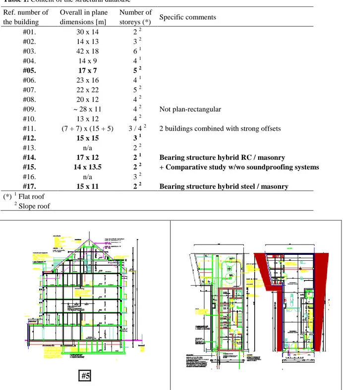
In order to cover a wide range of structural solutions and of applications of load-bearing masonry, a set of case-studies corresponding to "as built" examples have been collected. Their main characteristics are summarized in Table 1.
As a preliminary selection, some buildings have been chosen within the above list in order to investigate specifically identified situations:
Comparison of family houses ("villa" type) and buildings for apartments, and thus effect of the number of storeys;
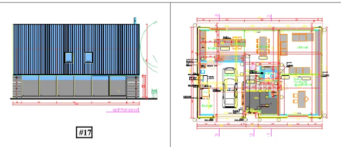
Comparison of family-house-format building with similar dimensions but with sloped or flat roof;
Multi-storey buildings with largely open ground floor;
Buildings with plain shear walls in one direction and with frame structural behaviour in the other direction.
In practice, 5 buildings of the database have been selected for a first round of pushover assessment. These buildings are highlighted in Table 2 with general drawings provided in Figure 2. It is important to remind that none of these buildings have actually been designed with respect to earthquake regulations.
More precisely, building #5 is a typical mid-rise construction built in unreinforced load-bearing masonry (5 real levels + 2 attic levels). Comparison with building #12 (3 levels) and with the other 3 (typical family houses with one or two levels) is aiming at investigating the effect of the number of storeys. Comparison of buildings #14 and #17 focuses on the difference between slope and flat roof with all other characteristics being rather similar. Building #15 (actually two neighbouring houses with a common wall) has also been specifically chosen for performing a comparison of the
consequences of the implementation of soundproofing devices aiming at a better comfort of people in the two adjacent dwellings With respect to this issue of soundproofing and on its impact on the seismic behaviour, see also (Lascar et al, 2012) and (Mordant et al, 2013).
It is also relevant to notice the large openings in the two short façades for building #5, as well as for one of the two long façades in buildings #14 and #17. Finally, it is of prime importance to note that, as emphasized in Figure 2 for building #12, floors are realized by using prefabricated concrete slab elements spanning in one direction. This implies that the shear walls in one direction are significantly more loaded by gravity loads than shear walls in the other direction, with important consequences on their resistance to horizontal loads, regarding both shear and overturning phenomena.
Table 1. Content of the structural database Ref. number of
the building
Overall in plane dimensions [m]
Number of
storeys (*) Specific comments
#01. 30 x 14 2 2 #02. 14 x 13 3 2 #03. 42 x 18 6 1 #04. 14 x 9 4 1 #05. 17 x 7 5 2 #06. 23 x 16 4 1 #07. 22 x 22 5 2 #08. 20 x 12 4 2 #09. ~ 28 x 11 4 2 Not plan-rectangular #10. 13 x 12 4 2
#11. (7 + 7) x (15 + 5) 3 / 4 2 2 buildings combined with strong offsets
#12. 15 x 15 3 1
#13. n/a 2 2
#14. 17 x 12 2 1 Bearing structure hybrid RC / masonry
#15. 14 x 13.5 2 2 + Comparative study w/wo soundproofing systems
#16. n/a 3 2
#17. 15 x 11 2 2 Bearing structure hybrid steel / masonry (*) 1 Flat roof
2 Slope roof
#12
#14
#17
Figure 2. Illustrations of the selected buildings (#5, 12, 14, 15 and 17 of the general database)
3 MATERIAL CHARACTERIZATION
As stated in section 1, this study is focusing on modern clay masonry with thin horizontal mortar layers and with vertical open joints. It takes place in a wider context comprising experimental studies carried out on a same type of units (Figure 1.a). Specific characterizations have been performed for such units and masonry. They can be summarized as follows:
Normalised compressive strength of units (EN 772-1 Annex A): fb = 13 N/mm² Measured characteristic masonry compressive strength (EN 1052-1): fk = 5.6 N/mm² Characteristic compressive strength (EN 1996-1-1): fk = 4.2 N/mm² Characteristic compressive strength (NBN-EN 1996-1-1): fk = 3.9 N/mm²
No specific characterization has been carried out for shear behaviour. Usual standard values are considered for further assessment:
Initial shear strength (NBN-EN 1996-1-1): fvk0 = 0.3 N/mm²
Characteristic shear strength (NBN-EN 1996-1-1): fvk = fvk0 + 0.4 d ≤ 0.045 fb (= 0.585 N/mm²) The material properties in terms of deformability are conservatively taken equal to the values proposed by EN 1996-1-1 and EN 1998-1 (i.e. E = 500 fk and G = 0.4 E), although showed in (Mordant et al, 2013) that values obtained from recent test results are actually smaller. However, for the seismic assessment and for the considered range of periods, overestimating the stiffness, and hence underestimating the period, should be on the conservative side. According to NBN EN 1998-1, the partial safety factor for the seismic design of masonry structures is taken equal to M = 1.5.
Moreover, in view of assessing the consequences of the use of soundproofing devices on the global seismic impact, specific experimental comparative tests have been carried out on small and full-scale masonry specimens with and without acoustic rubber layers in cyclic and dynamic conditions, as presented in (Lascar et al, 2012) and (Mordant et al, 2014). Although some of these tests are still to be further processed (in particular with respect to the modifications in terms of deformation capacity), a first conservative conclusion yields that, in presence of rubber layers, the horizontal stiffness of the wall is roughly reduced to 1/3rd of the stiffness of the plain masonry, while its resistance to horizontal loads is reduced to one half of the resistance of the plain masonry.
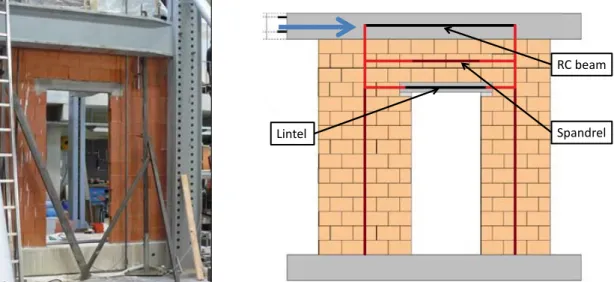
Finally, in the perspective of calibrating the equivalent frame model and the pushover procedure that will be described in the next section, full scale cyclic tests have been carried out on a wall with a door opening with a concrete lintel and a concrete beam representative of the bending stiffness of a one metre wide floor slab (see Figure 3.a). These tests are presented in (Degée et al, 2012).
4 MODELLING AND ASSESSMENT PROCEDURE
The present study is using a rather common equivalent frame modelling solution in which the different walls are considered as beam or columns (including the contribution of shear to the deformability of the system) and where the verification procedures are based on generalized stresses (normal forces, bending moments and shear forces). As a matter of example, Figure 3.b is showing the axes of the different equivalent beam elements for the test specimen of Figure 3.a. The axes in red correspond to rigid arms allowing appropriate offsetting of the different elements. Masonry panels situated at the intersection of vertical and horizontal masonry elements are also considered as infinitely rigid. Torsional effects associated with a possible offset of the centre of stiffness with respect to the centre of mass of the floors (particularly significant in case of widely open façades) are taken into consideration assuming that concrete floors behave as perfectly rigid diaphragms.
Figure 3. (a) Test specimen – (b) Equivalent frame model
Characterization of the capacity of the structures to sustain horizontal loads is obtained by a classical pushover method. Pushover curves are derived with the home-made software FinelG using the following procedure:
Calculate the distribution of normal forces in the vertical walls due to gravity load, with due account for the spanning direction of the floors;
Perform a linear elastic analysis of the entire structure subjected to a normalized triangular distribution of horizontal forces;
Determine the load level corresponding to reaching its failure load for the weakest structural element. Failure modes taken into consideration are the overturning of the wall (compressive length becoming equal to zero), the compression failure and the shear failure. Failure loads are determined according to EN 1996-1-1;
When a wall reaches its failure load, it is replaced by a simple vertical support, i.e. the wall is still able to sustain gravity loads but will not contribute to resisting additional horizontal loads;
Horizontal loads are incremented until all walls have reached their maximum load capacity; RC beam
Spandrel Lintel
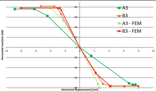
Horizontal displacement of all walls is monitored during the entire procedure and the curve is cut when one of the walls reaches its maximum deformation capacity. Maximum deformation is estimated on the base of the proposals from (Oropeza, 2011), derived from experimental databases and depending on the aspect ratio of the wall and of its average compressive stress. As a matter of example and validation of the method, Figure 4 shows the comparison of the pushover curves obtained with the above methodology and of the backbone curves of the cyclic tests of Figure
3. In this comparison, A3 refers to a configuration with a normal lintel configuration (support length
equal to 15 cm) while B3 refers to a modified configuration with longer lintels (support length equal to 45 cm).
Figure 4. Comparison of experimental and numerical pushover curves
This comparison shows that (i) the strength is well predicted, (ii) the overall stiffness is in the range of the test results (note that a rather important difference is observed between the two tests) and (iii) the deformation capacity is in the range of the test results, although slightly overestimated for the long lintel configuration. An additional validation has also been carried out with respect to results obtained from shake table tests but this comparison is not presented in the present paper.
Interpretation of the pushover curves in terms of acceptable levels of ground acceleration is then carried out using the N2-method, such as recommended by the informative annex B of EN 1998-1.
5 RESULTS
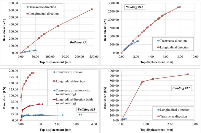
The pushover procedure has been applied to the selected set of five buildings. Figure 5 shows the capacity curves obtained for each of these buildings and for seismic forces acting along the longitudinal and transverse direction respectively. As announced, for building #15, a comparison is carried out between situations with and without rubber soundproofing systems.
The following observations can be drawn from these curves:
For each building, a huge difference is observed between the two main directions, both in terms of stiffness and of resistance. This situation is related to the preferential spanning direction of the floors, with the consequence that, when only gravity loads are considered in the design, there is no need of walls in both directions, leading to extremely open situations with a completely insufficient level of stiffness and resistance (see in particular buildings #5
-80 -60 -40 -20 0 20 40 60 80 -10 -8 -6 -4 -2 0 2 4 6 8 10 Ho ri zo n ta l r ea cti o n s [kN ] Horizontal displacement [mm] A3 B3 A3 - FEM B3 - FEM
and #17). Moreover, even in cases where the number of walls in the non-bearing direction remains reasonable (see for instance building #12 where the initial stiffness is similar in both directions), these walls are not subjected to a significant compression level (i.e. they are loaded only by their self-weight) and are thus less resistant to overturning and shear.
For most of the typical architectural situations studied, no clear "yielding plateau" can be identified. Although some redistribution capacity is observed, the overall deformation capacity remains limited by the fairly brittle behaviour of the weakest walls that reach their ultimate displacement before the full load redistribution can develop.
The presence of the rubber soundproofing devices clearly modifies the overall structural response in terms of stiffness, strength and deformation capacity.
Figure 5. Pushover curves for buildings #5, #12, #15 and #17
The previous observations provide qualitative information on the seismic behaviour of the buildings that may appear rather frightening if taken in an absolute context. These results must however be put in relation with:
The seismic demand, in particular in terms of total mass. For instance, in the most resistant direction, the maximum horizontal resistance of buildings #5 and #17 are of the same order of magnitude, while the first one comprises 7 storeys and the latter only 2.
The real seismic hazard of countries like Belgian or neighbouring countries. According to the different regions considered, design ground acceleration at the bedrock is ranging from 0.04 to 0.1 g (it may even be equal to 0.0 in some place, but in those cases, the present study has actually no relevance…). Including the soil coefficients associated with Eurocode 8/type 2 spectra, the full practical range is thus from 0.04 to 0.18 g.
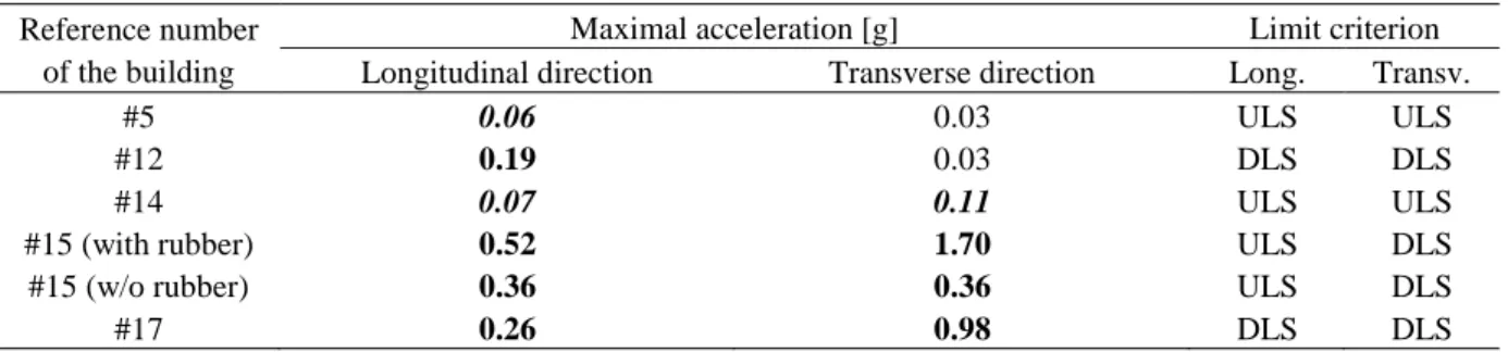
In order to evaluate the actual risk, pushover curves are exploited in terms of performance point, using the N2 method. Maximum sustainable ground acceleration corresponding to reaching the end of the
pushover curves are given in Table 2. For the sake of completeness, a verification of the damage limit state based on a limit of 1 % of inter-storey drift is also taken into consideration and is in some cases likely to become more critical than the ultimate limit state. In this table, cases where the building is able to sustain the maximal possible acceleration for the zone are highlighted in bold. If the building could be able to sustain the design acceleration to some extent but not on the full possible range, values are highlighted in italic. The two remaining cases correspond to situations where the building is unable to reach the very minimal required acceleration.
Table 2. Maximum sustainable acceleration Reference number
of the building
Maximal acceleration [g] Limit criterion
Longitudinal direction Transverse direction Long. Transv.
#5 0.06 0.03 ULS ULS
#12 0.19 0.03 DLS DLS
#14 0.07 0.11 ULS ULS
#15 (with rubber) 0.52 1.70 ULS DLS
#15 (w/o rubber) 0.36 0.36 ULS DLS
#17 0.26 0.98 DLS DLS
From Table 2, the following observations can be drawn:
For low-rise buildings (buildings #15 and #17, comprising one level plus attic), even if the capacity of the building seems very low in one direction, the seismic demand remains limited and can be fulfilled by usual non seismic wall configurations. It is also relevant to note that, for the case of an earthquake acting in the weakest direction, the behaviour is governed by the damage limit state criterion (although activated for accelerations far above the requested level), showing that the issue is more on the stiffness side than on the strength side.
The presence of rubber soundproofing elements is reducing significantly the maximal sustainable acceleration. However, in case of low-rise buildings, it remains larger that the requested level. This should be deeper investigated in case of high-rise buildings. Moreover, it is relevant to note that the reduction is more important when the governing limit state is the damage limitation. This is due to a larger impact of the rubber on the storey deformability than on the wall resistance.
For moderately high buildings (2 to 3 storeys, buildings #12 and #14), the situation starts becoming critical according to the direction considered and to the arrangements of the walls and of the spanning direction of the floors. The maximum acceleration level could be accepted in some zones and not in others where additional measures should be taken. It is also to be noted that, in case #12, the governing limit state is the damage limitation. Not considering this criterion would have led to maximal accelerations of respectively 0.25 and 0.05 g, which nevertheless does not save the situation when the shear walls are not loaded by gravity. This shows that in such a situation, the contribution of the walls perpendicular to the seismic action, acting as flanges and loaded by the gravity, may help in the seismic stability of the building and improve as well the damage issue by increasing the storey stiffness. This topic is currently under investigation by the authors of the present paper.
For high rise buildings, the situation is becoming very critical. Indeed, even when the shear walls are under compression due to the gravity loading, the base shear and overturning moment at the base of the building associated with the total mass of more than 5 storeys is becoming extremely large even for small accelerations. This situation is also not balanced by any significant deformation capacity (i.e. from the pushover curves, the associated behaviour factor could hardly be estimated above 1.5 to 2.0). Specific solutions should be investigated for such situations, like for instance the combination of load bearing masonry with reinforced concrete elements, the use of confined or reinforced masonry or the development of any specific solution that may improve the deformation capacity of the walls, since in this case,
the governing limit state is not the damage limitation. It must also be noted that some aspects that could contribute in uprising the maximum sustainable acceleration were not considered in the analysis because hardly possible to be quantified, e.g. rocking effect of the wall (well-known as contributing to the energy dissipation in RC walls, but not considered yet for masonry) or contribution of the bending stiffness of the floors.
6 CONCLUSIONS
The paper has presented a set a pushover analyses carried out on typical North-West European buildings not designed for earthquake, using a numerical tool and a pushover procedure duly validated on experimental results. The main conclusions are that
(i) The preferential spanning direction of the floors and the architectural wish for widely open façades are inducing a large dissymmetry in the seismic behaviour,
(ii) No significant risk is identified for low-rise family houses,
(iii) The use of rubber soundproofing systems is influencing significantly the seismic response of the buildings in particular in terms of deformability and hence on activation of the damage limitation criterion and
(iv) The situation is very critical for moderately high or high-rise unreinforced load bearing masonry buildings (from 3 to 6 levels) since the minimal required acceleration level is not reached if no other element that only the shear walls are considered.
ACKNOWLEDGEMENTS
The authors acknowledge the support received from the Wallonia, from the company Wienerberger and from the F.R.S.-FNRS (Belgian Fund for Research).
REFERENCES
Rouge. La Force. Reference document Wienerberger Belgium (2008). www.wienerberger.be.
Lascar, L, Degée, H, Vasseur, L. (2012) Etude du comportement sismique de bâtiments en maçonnerie portante de terre cuite utilisant des elements préfabriqués et respectant les exigences thermiques et acoustiques. Convention SPW FIRST 6231. Research report, partly in French.
Degée, H, Lascar, L, Vasseur, L. (2012) Seismic performance of thin-bed layered masonry walls made of clay blocks and comprising a door opening. Proceedings of the 15th World Conference on Earthquake Engineering, paper n° 2275.
Degée, H, Mordant, C, Lascar, L, Vasseur, L. (2013) Assessment of the seismic performances of modern unreinforced family houses and multi-storey clay masonry buildings. Proceedings of the COMPDYN Conference.
Mordant, C, Dietz, M, Taylor, C, Plumier, A, Degée, H. (2014) Seismic behaviour of thin-bed layered unreinforced clay masonry shear walls including soundproofing elements. In Seismic Evaluation and Rehabilitation of Structures. Springer International Publishing. In press.