University of Li`ege
Aerospace and Mechanical Engineering Department Spatial Instrumentation and Experimentation
Centre Spatial de Li`ege
Conception and Design of
New Space
Instrumentation for the
Study of Massive Stars in
the UV
Advisor Prof. Pierre Rochus
co-Advisor Prof. Gregor Rauw
Thesis submitted in fulfilment of the requirements for the degree of Doctor in Engineering Sciences
by
Richard Desselle, Ir.
Author’s contact details Richard DESSELLE
Centre Spatial de Li`ege University of Li`ege Li`ege Science Park Avenue du Pr´e-Aily 4031 Angleur, Belgium e-mail: rdesselle@ulg.ac.be phone: +32 43 82 46 67
Members of the Examination Committee
Prof. Ga¨etan KERSCHEN (President of the Committee) University of Li`ege (Li`ege, Belgium)
email: G.Kerschen@uliege.be Prof. Pierre ROCHUS (Advisor)
University of Li`ege - Centre Spatial de Li`ege (Li`ege, Belgium) e-mail: prochus@uliege.be
Prof. Gregor RAUW (Co-advisor) University of Li`ege (Li`ege, Belgium) e-mail: G.Rauw@uliege.be
Dr. Coralie NEINER
Observatoire de Paris (Paris, France) e-mail: Coralie.Neiner@obspm.fr Prof. Stefanos FASOULAS
University of Stuttgart (Stuttgart, Germany) e-mail: fasoulas@irs.uni-stuttgart.de
Dr. Pierre ROYER
KU Leuven (Leuven, Belgium) e-mail: pierre@ster.kuleuven.be Prof. Ya¨el NAZE
University of Li`ege (Li`ege, Belgium) e-mail: ynaze@uliege.be
Abstract
In astrophysics, the UV domain is rich in important information that can be exploited by a multitude of groups of scientists, working on a variety of subjects. Because of the Earth’s atmosphere, it is not possible to observe this spectral do-main from the ground and therefore space observatories are needed to provide the scientific data. Motivated by the study of the properties of massive stars in the UV, this thesis is devoted to the design of new space instrumentation dedicated to this scientific purpose.
In the first part, the conception of an in-flight calibration unit is investigated to answer the needs of a large instrument proposed to ESA calls for medium-sized missions. The technologies available are identified and presented before being ac-commodated to the current instrument.
The second part is dedicated to UV instrumentation on-board very small satel-lites that are based on the Cubesat standard. After presenting the standard and previous Cubesat missions, feasibility studies of two instruments are conducted. The first instrument is a near-UV telescope designed to be integrated in a 3U Cubesat. The optical design, the entire satellite and a mission analysis are discussed. Based on all the previous points, a photometric budget is carried out to demonstrate the efficiency of the system. The second instrument is a near-UV low-resolution spec-tropolarimeter which is presented as a potential technology demonstrator in relation with the above-described medium-sized mission.
Conclusions and perspectives are presented and discussed in the third part of this thesis.
Acknowledgments
Before all else, I would like to express my sincere gratitude to my advisor and co-advisor Prof. Pierre Rochus and Prof. Gregor Rauw for their guidance through-out this thesis. Especially, I thank Prof. Gregor Rauw for his advice, his time and his inputs without which I could not go through the end.
Besides my advisors, I would like to thank the rest of my thesis committee, Prof. Ya¨el Naz´e, Prof. Serge Habraken and Yvan Stockman who provided regular feed-back about my work.
I am also pleased to acknowledge Prof. Ga¨etan Kerschen from the University of Li`ege, Dr. Coralie Neiner from the Observatoire de Paris, Prof. Stefanos Fasoulas from the University of Stuttgart and Dr. Pierre Royer from the KU Leuven for accepting to participate in the examination committee of this thesis.
For the friendly working atmosphere, I wish to thank all my friends and col-leagues from the Centre Spatial de Li`ege (CSL). In particular, I would like to thank Christian Kintziger who was also involved in the Action de Recherche Concert´ee (ARC) and with whom I had the chance to work during these fours years. I wish also to thank J´erˆome Jacobs with whom I shared an office since my arrival at the CSL and with whom I had so many interesting discussions. I wish also to thank Etienne Renotte who was involved in the preparation of Arago and who has spent so many missions with me in Paris.
This research was funded through an ARC grant for Concerted Research Actions, financed by the French Community of Belgium (Wallonia-Brussels Federation).
Last but not least, I would like to thank my family and friends for their con-tinuous support and encouragements. Especially, all of this would not have been possible without the support and the love of my wife Justine.
Contents
Contents 11 List of Acronyms 16 Introduction 19 Context . . . 19 Subjects Overview . . . 20I
Preparation of an On-board Calibration Unit Concept
for a Major Space Mission
22
1 On-board Calibration Principles 23 1.1 Calibration of Scientific Space Instruments . . . 231.1.1 Principles . . . 23 1.1.2 CSL Heritage . . . 24 1.1.2.1 OLCI . . . 24 1.1.2.2 UVN . . . 26 1.2 Calibration Elements . . . 27 1.2.1 Celestial Standards . . . 27
1.2.2 White Light Sources . . . 28
1.2.3 Hollow Cathode Lamps . . . 30
2 Application to the Arago Mission for the M4 and M5 Calls from ESA 31 2.1 Mission Presentation . . . 31
2.1.1 Scientific Objectives . . . 31
2.1.2 UV and Visible Spectropolarimetry . . . 32
2.1.3 Circular and Linear Spectropolarimetry . . . 32
2.1.4 Instrument . . . 32
2.2 Perimeter of Belgian Activities . . . 33
2.3 Calibration Requirements . . . 33
2.3.1 Offset . . . 33
2.3.2 Dark . . . 34
2.3.3 Flat Field . . . 34
2.3.3.1 Pixel Response Non Uniformity . . . 34
2.3.3.3 Linearity . . . 34
2.3.4 Relative Spectral Response Function . . . 35
2.3.5 Wavelength Calibration . . . 35
2.3.6 Calibration of Polarization . . . 35
2.3.7 Intra-pixel Response Non Uniformity . . . 36
2.4 Calibration Unit Preliminary Design . . . 37
2.4.1 Block Diagram . . . 37
2.4.2 Calibration Light Sources . . . 37
2.4.2.1 Flat Field Sources . . . 37
2.4.2.2 Wavelength Calibration Source . . . 39
2.4.3 Mechanical Parts . . . 40
2.4.3.1 Calibration Unit Box . . . 40
2.4.3.2 Injection Point Box . . . 42
2.4.4 Power Supply Considerations . . . 43
II
Very Small Missions Feasibility Studies
45
3 Cubesats Missions 46 3.1 Cubesat Standard . . . 463.1.1 Overview . . . 46
3.1.2 Interests for Cubesats . . . 47
3.2 Cubesats in Astronomy and Astrophysics . . . 48
3.2.1 BRITE . . . 48
3.2.2 CXBN-2 . . . 50
3.2.2.1 ASTERIA . . . 51
3.2.3 PicSaT . . . 53
3.2.3.1 HaloSat: a mission under development . . . 54
3.2.4 Perspectives . . . 54
4 Feasibility Study of a UV Photometer On-board a 3U Cubesat 55 4.1 Proposed Instrument and Mission . . . 55
4.2 Optical Design . . . 57
4.2.1 Basic Considerations and Constraints . . . 57
4.2.1.1 Volume Constraints . . . 57
4.2.1.2 Field of View . . . 57
4.2.1.3 Effective Focal Length . . . 59
4.2.1.4 Number of Pixels and Focal Plane Size . . . 60
4.2.1.5 Filter . . . 61
4.2.1.6 Conic Constants and Radii . . . 61
4.2.2 Design Characteristics . . . 62
4.2.2.1 Geometry . . . 62
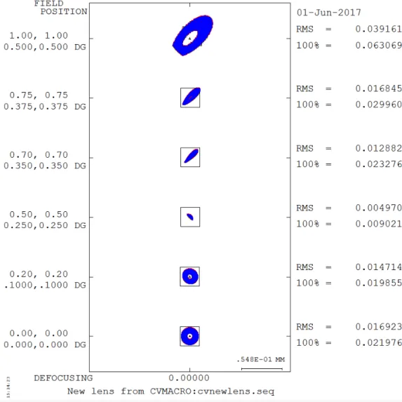
4.2.2.2 Spot Diagram . . . 63
4.2.2.3 Modulation Transfer Function (MTF) . . . 66
4.2.2.4 Baffling System . . . 69
4.2.2.5 Stray Light Analysis . . . 72
4.3.1 Solar Panels Configuration . . . 76
4.3.1.1 Table Configuration . . . 76
4.3.1.2 Cross Configuration . . . 77
4.3.1.3 Sky Visibility . . . 78
4.3.1.4 Comparison of the Configurations . . . 81
4.3.2 Detector Choice and Characteristics . . . 82
4.3.2.1 Back-Thinned CCD . . . 82
4.3.2.2 CMOS . . . 83
4.3.2.3 Microchannel Plates (MCP) . . . 84
4.3.2.4 Conclusion . . . 86
4.3.3 Data Storage and Transfer . . . 87
4.3.4 Attitude Considerations . . . 89
4.3.4.1 Pointing . . . 89
4.3.4.2 Jitter Noise . . . 90
4.4 Thermal Environment and Analysis . . . 92
4.4.1 Orbit Definition . . . 92
4.4.1.1 Launch Constraints . . . 92
4.4.1.2 Orbit Propagation . . . 93
4.4.2 Thermal Considerations . . . 95
4.4.2.1 External Thermal Loads . . . 95
4.4.2.2 Internal Thermal Loads: Power Budget . . . 96
4.4.2.3 Thermal Model . . . 100
4.4.2.4 Results for the Worst Thermal Cases . . . 101
4.5 Photometric Budget . . . 106
4.5.1 Basic Equations . . . 106
4.5.2 Modelling . . . 108
4.5.3 Interstellar Absorption AV . . . 109
4.5.4 Observation Strategy . . . 110
4.5.4.1 Total Efficiency of the Telescope . . . 110
4.5.4.2 Signal to Noise Ratio (SNR) . . . 111
4.5.4.3 Saturation Issues . . . 114
5 Feasibility Study of a Low-Resolution UV Spectropolarimeter on-board a Cubesat 117 5.1 Proposed Instrument and Mission . . . 117
5.2 Optical Design . . . 119
5.2.1 Polarimeter . . . 119
5.2.1.1 Fundamentals . . . 119
5.2.1.2 Polarimeter Design . . . 120
5.2.1.3 Mueller Matrix Calculation . . . 121
5.2.1.4 Material Selection . . . 122 5.2.1.5 Simulations . . . 123 5.2.2 Telescope . . . 126 5.2.3 Spectrometer . . . 126 5.3 Achievable Performances . . . 127 5.3.1 Field of View . . . 127
5.3.2 Signal to Noise Ratio . . . 128 5.4 Proposed Cubesat Platform . . . 131
III
Conclusions and Perspectives
133
6 Conclusions and Perspectives 134
6.1 PART I: Preparation of an On-board Calibration Unit Concept for a Major Space Mission . . . 134 6.1.1 On-board Calibration Principles . . . 134 6.1.2 Application to the Arago Mission for the M4 and M5 Calls
from ESA . . . 134 6.2 PART II: Very Small Missions Feasibility Studies . . . 135 6.2.1 Cubesats Missions . . . 135 6.2.2 Feasibility Study of a UV Photometer On-board a 3U Cubesat 135 6.2.3 Feasibility Study of a Low-Resolution UV Spectropolarimeter
on-board a Cubesat . . . 137 6.3 General Conclusion . . . 138
Bibliography 139
Appendices 147
A Polarimetry Basic Principles 148
A.1 Stokes Parameters . . . 148 A.2 Mueller Matrices . . . 149 A.3 Jones Matrices . . . 150
B Orbital Considerations 151
B.1 Orbital Parameters . . . 151 B.2 β Angle and Eclipse Duration . . . 152 B.3 Sun-Synchronous Orbit . . . 155
List of Acronyms
AC Alternative Current
ACS Advanced Camera for Surveys
ADCS Attitude Determination and Control System ARC Action de Recherche Concert´ee
ASTA Astrophysique Stellaire Th´eorique et Ast´erosismologie
ASTERIA Arcsecond Space Telescope Enabling Research in Astrophysics BOL Beginning Of Life
BRITE BRIght Target Explorer CAD Computer-Aided Design CCD Charge Coupled Device
CMOS Complementary Metal Oxide Semi-conductor CoG Center of Gravity
COS Cosmic Origins Spectrograph COTS Component Off-The-Shelf CSL Centre Spatial de Li`ege
CXBN Cosmic X-ray Background Nanosatellite CZT Cadmium Zinc Telluride
ECI Earth-Centered Inertial
EGSE Electrical Ground Support Equipment EIT Extreme ultraviolet Imaging Telescope
EM Electromagnetic
EOL End Of Life
ESA European Space Agency FEM Finite Element Model FOC Faint Object Camera
FoV Field of View
FF Flat Field
FUSE Far Ultraviolet Spectroscopic Explorer
GAPHE Groupe d’Astrophysique des Hautes Energies GMM Geometrical Mathematical Model
HCL Hollow Cathode Lamp
HST Hubble Space Telescope
IPRNU Intra-Pixel Response Non Uniformity
IR Infrared
IUE International Ultraviolet Explorer ISS International Space Station JPL Jet Propulsion Laboratory KUL Katholieke Universiteit Leuven LEO Low Earth Orbit
LESIA Laboratoire d’´etudes spatiales et d’instrumentation en astrophysique LoS Line-of-Sight
LWA Lamp Wheel Assembly
LUVOIR Large UV/Optical/Infrared Surveyor MCP Microchannel Plate
MTF Modulation Transfer Function NIR Near-Infrared
NASA National Aeronautics and Space Administration
OBC On-Board Computer
OLCI Ocean and Land Colour Instrument P-POD Poly Picosatellite Orbital Deployer PCB Printed Circuit Board
PRNU Pixel Response Non Uniformity PSF Point Spread Function
QE Quantum Efficiency QTH Quartz Tungsten Halogen
RAAN Right Ascension of the Ascending Node
RMS Root Mean Square
RSRF Relative Spectral Response Function SED Spectral Energy Distribution
SL Stray Light
SNR Signal to Noise Ratio
SSO Sun-Synchronous Orbit (SSO) STK Satellite Tool Kit
SWIR Short-Wave Infrared
TMM Thermal Mathematical Model TRL Technology Readiness Level UTC Universal Time Coordinated
UV Ultraviolet
UVN Ultraviolet Visible Near-infrared WLS White Light Source
WP Work-Package
Introduction
Context
Genesis of the Project
The project associated to this PhD thesis is part of an Action de Recherche Concert´ee (ARC) which is dedicated to the study of Massive Stars. This ARC brings together the following research entities from the University of Li`ege: the Groupe d’Astrophysique des Hautes Energies (GAPHE), the Astrophysique Stellaire Th´eorique et Ast´erosismologie (ASTA) team and the Centre Spatial de Li`ege (CSL). The main aspects of space research treated within this ARC are: the fundamental understanding of massive stars which is the main concern of the GAPHE and ASTA teams and the instrumental design for observing these stars (under the responsibility of the CSL). The association of all these entities is fully complementary in order to carry out the overall ARC project.
Study of Massive Stars in the UV
Massive stars are very hot and luminous stars which have a tremendous impact on their surroundings via their powerful stellar winds and huge UV luminosities. The combination of these winds, the strong ionizing radiation fields as well as the death of these stars in gigantic supernova explosions make massive stars major play-ers for the evolution of the Univplay-erse.
The ARC is divided in seven work-packages (WP), four of them corresponding to PhD theses dedicated to specific aspects of the study of massive stars. The four topics covered by PhD theses are listed below. The WP concerned by the present manuscript corresponds to the #4.
• WP #1: Study of chemical abundances of fast rotating OB stars; • WP #2: Study of fundamental parameters of massive stars in binaries; • WP #3: Development of a near-IR spectrometer;
• WP #4: Development of new space instrumentation in the ultraviolet (UV).
Since the termination of the International Ultraviolet Explorer (IUE) mission in 1996 and the end of the Far Ultraviolet Spectroscopic Explorer (FUSE) in 2007, the UV domain suffers from a lack of dedicated instrumentation. The Hubble Space Telescope nevertheless allows to observe in the UV thanks to the STIS and COS spec-trographs, but they share the available observing time with other instruments work-ing in the visible and near-IR domain. Lookwork-ing towards the next few years, whilst several IR space observatories are under construction or in the planning (JWST [1] or SPICA [2] for examples), there is currently no mid- to far-UV mission at a similar level of preparation. Yet, the UV domain has a large diagnostic power, especially for the study of bright massive stars as they have their spectral energy distribution peaking in the UV.
In this WP, it is proposed to investigate two aspects of space missions. First, the working groups are involved in the Arago consortium, aiming at proposing a spaceborne UV/Optical spectropolarimeter in response to the ESA calls for medium-sized missions. Second, it is proposed to conduct feasibility studies of Cubesats with small UV telescopes and associated instruments.
Subjects Overview
Preparation of an On-board Calibration Unit Concept for a
Major Space Mission
In order to fully understand observed signals and translate them into scientific data, an accurate knowledge of the observing instrument is required. The calibra-tion of the instrument is thus an important part of the design process of a mission [3]. The methods for the calibration of on-board space telescopes are divided into three categories [3]:
i. Pre-flight calibration which is performed at system or sub-systems levels in the laboratory;
ii. Calibration in orbit using celestial standards;
iii. Calibration by use of a transfer standard that is carried into and operated in orbit as part of the scientific payload.
In the context of the preparation of the Arago mission, all these aspects have to be considered and more specifically the third one because it is the most complex. In-deed, the proposed instrument is a high-resolution spectropolarimeter working both in the UV and in the optical domains. This kind of instrument is very complex and
needs a very deep knowledge of its intrinsic properties to analyse the data.
The first part of the manuscript will be dedicated to the presentation of the on-board calibration tools and how they could be used to design a calibration unit that fills the needs of an instrument such as the one of Arago. The Arago instrument and mission have been proposed in response to two medium size mission calls from ESA, i.e. M4 and M5. Although the proposal was so far unsuccessful, the work presented here will serve either in a future re-submission of the project to ESA or could be used for the integration of a similar instrument into a larger UV satellite (Pollux on LUVOIR [4], for example) to be proposed to NASA.
Very Small Missions Feasibility Studies
Since the creation of the Cubesat standard in 1999 and its first launch in 2003 [5][6], a huge number of Cubesat missions have been elaborated, launched and operated successfully. Even though miniaturizing processes are often challenging, these small satellites are now considered as an important support for education at University level and also for scientists all over the world for observation from space. The fea-sible scientific observations with such small satellites are diverse, from Earth and atmosphere observation with QuakeSat [7] or SwissCube-1 [8] to visible photometry of bright stars with the BRITE constellation [9]. It shows that, even though Cube-sats will not entirely replace large spacecrafts and missions, there are a wide range of scientific fields where they can enable innovative focused research [10]. Moreover, Cubesats can serve as demonstrators for new technologies planned on future larger satellites.
The second part of this manuscript is thus dedicated to feasibility studies of scientific Cubesats embarking UV telescopes designed for the observation of massive stars. The first Cubesat envisages a 3U design containing a reflective UV telescope that is able to acquire time series of bright massive stars in the UV domain between 250 and 350 nm. The second Cubesat should embark a UV telescope and a low-resolution static spectropolarimeter that could be used as a technology demonstrator for future missions.
Part I
Preparation of an On-board
Calibration Unit Concept for a
Chapter 1
On-board Calibration Principles
1.1
Calibration of Scientific Space Instruments
1.1.1
Principles
Every space optical instrument has to be calibrated in order to know how it responds to a light source and therefore analyse and interpret the observations col-lected. For a telescope-spectrometer system, for example, many parameters have to be monitored such as the overall transmittance/reflectance of the optical elements, their wavelength response and the sensitivity of every pixel of the sensor that regis-ters the end signal. It has to be stressed though that there exists no unique recipe to calibrate an instrument. The type of calibration data that are needed depends on the nature of the instrumentation and its usage, and frequently even changes over the lifetime of the instrument.
The first step is the pre-flight calibration which is done in laboratory and at every required level (systems or sub-systems). This pre-flight calibration is usually performed inside vacuum chambers where the in-flight conditions of operation are simulated (pressure, temperature) and the targets (stars, Sun, Earth) are repro-duced using light sources. For traditional missions, this calibration is a part of the qualification test campaign that serves to validate the mission/instrument design and performance.
The second and last step is the in-flight calibration which is done during the space operations. In general, it is necessary to be able to repeat the calibration performed pre-flight to monitor all the parameters of the instrument which could change over the lifetime of the mission. Indeed, the sensor is aging and its pixel responses will change, the coatings of the mirrors could be contaminated or damaged by large levels of radiation, and so on. Recreating the pre-flight calibration during the mission is quite a challenge because of the complexity of current instruments and the precision that is required. As already mentioned in the Introduction Section, two methods are available for the in-flight calibration:
• Use of celestial standards: it is possible to observe very well-known and con-stant targets that will allow calibrating the whole optical path of the instru-ment, telescope included. However, these standards are usually observed from the ground. The differences between conditions during ground observation and in-orbit operations could be a concern. In this context, the UV domain is special as it is not observable from the ground and then the usual standards could be used for UV instruments only by extrapolation of the results in other wavelength ranges by use of theoretical models [3].
• Use of in-flight calibration light sources that are integrated to the payload. The disadvantage is that with this method it is not possible to calibrate the whole optical path because generally these light sources are located inside the instrument and are not illuminating the entrance of the telescope because of technical constraints and the fact that it is impossible to artificially create a point source illuminating the telescope from an infinite distance.
1.1.2
CSL Heritage
CSL has a long heritage in space instruments design and testing for many mis-sions from ESA and NASA. CSL has designed and tested the in-flight calibration module for many instruments, and this section presents two of them which are the most recent ones. The common point of these calibration modules is that they are using a wheel mechanism for switching between the different calibration modes and/or observation. These kinds of systems are often complex and considered as possible single points of failure in many cases because if they fail, either the calibra-tion no longer works and the performance degrades or the instrument can no longer be used at all. Therefore the development and the qualification of these components are very critical.
1.1.2.1 OLCI
The Ocean and Land Colour Instrument (OLCI) is an instrument on-board the Sentinel-3 satellite from ESA [11]. Sentinel-3 is part of the Sentinel fleet of satellites which belongs to the Copernicus programme for Earth observation. The main focus of Sentinel-3 is the observation of oceans through the measurement of temperature, colour and height of the sea surface as well as the thickness of sea ice. These mea-surements allow to monitor changes in sea level, marine pollution and biological productivity. Sentinel-3 is also designed for land observation [11].
OLCI fulfils the objectives of ocean colour determination, as well as some land-cover objectives by simultaneously observing the Earth in 21 spectral bands from the visible at 390 nm to the SWIR (short-wave infrared) at 1040 nm. The instru-ment is composed of five identical cameras which are pointed towards the Earth. It also hosts a calibration assembly which is made of a positioning mechanism and the associated reference diffusers that re-calibrate the cameras in-flight [12]. Figure 1.1 presents the calibration assembly as it was integrated in the clean room of CSL.
Figure 1.1: Picture of the calibration assembly of the OLCI instrument integrated in the CSL clean room [12].
The diffusers of the calibration assembly work in reflection and allow to perform a photometric and a spectral calibration of the cameras. While the instrument is in its calibration mode, the assembly is oriented to observe the Sun and the dif-fusers reflect the incoming light to the cameras. There is a total of three difdif-fusers positioned on a rotating wheel assembly: the first diffuser is used as white reference for photometric calibration, the second is redundant to the first one and the last diffuser is used for wavelength calibration. The mechanism also has two other po-sitions used during actual Earth observation (calibration is ”off”: no diffuser in the optical path) and for dark calibration (there is a shutter that blocks the calibration light from reaching the cameras). Figure 1.2 presents the wheel assembly with its various components.
The example of the OLCI calibration unit is related to the first in-flight calibra-tion technique, i.e. the use of celestial standards. In this case, the standard is the Sun and its light is transformed by the different diffusers, that are very well charac-terized before flight, to perform specific calibrations (photometric or spectroscopic). The diffusers have to be characterized in laboratory with calibrated standard lamps. Moreover, the degradation of their properties with time has also to be monitored with accelerated ageing tests during which the diffusers are submitted to a large amount of radiation during a relatively short period to simulate the integrated dose of radiation of the entire mission.
Figure 1.2: Rotating filter wheel assembly of the calibration unit of OLCI. The three diffusers, the shutter and the free window for Earth observation are clearly visible in the picture [12].
1.1.2.2 UVN
The Ultraviolet Visible Near-infrared (UVN) is an instrument that will be on-board the Sentinel-4 satellite from ESA [13]. As Sentinel-3, Sentinel-4 is part of the Copernicus programme but this latter satellite is still in preparation. The Sentinel-4 mission will focus on monitoring the concentrations of trace gases and aerosols in the atmosphere for investigating the evolution of air-quality and climate, mainly over Europe [13].
UVN is a spectrometer that will be used for atmospheric observation in a wide range of wavelengths (from 305 to 500 nm in the UV/visible and from 750 to 775 nm in the NIR). Figure 1.3 presents a picture of the UVN calibration assembly in-tegrated in the clean room of CSL during its qualification test campaign.
The principle of the UVN calibration is based on two separate ways: the first calibration is performed by placing a diffuser between the detector and the Sun, as for OLCI, while the second calibration is performed by switching on an on-board White Light Source (WLS) which generates a collimated beam using a parabolic mirror, an integrating sphere and a slit. As for OLCI, there are a nominal diffuser for the first calibration and a redundant one. They are placed on a rotating fil-ter wheel assembly that has three different positions. The third position is for the parabolic mirror associated to the WLS. Figure 1.4 presents this wheel assembly.
In this example, the calibration unit uses the two in-flight calibration techniques. Indeed, the diffusers are used for a calibration using the Sun as a celestial standard while the WLS provides a well-known beam of light for the calibration of the in-strument. The Sun and WLS calibration light is injected in the UVN instrument thanks to a mechanism that allows to switch between observation and calibration modes.
Figure 1.3: Picture of the calibration assembly of the UVN instrument integrated in the CSL clean room.
Figure 1.4: Rotating filter wheel assembly of the calibration unit of UVN. The element on the right is the parabolic mirror and the other two are the diffusers.
1.2
Calibration Elements
1.2.1
Celestial Standards
Celestial standards are a relatively easy way to calibrate optical instruments during a space mission. Indeed, they do not require any on-board components that make the system more complex and that have to be studied, tested and qualified for flying. They can be used for flat field or even for wavelength calibration.
Celestial objects such as the planets of our solar system (Mars, Jupiter, Saturn), or well-known and luminous stars (including the Sun) are very good candidates for being standards for the calibration as they have been observed precisely from the ground with a lot of different instruments [3]. Calibrated ground-based observations are thus available, hence their spectral properties are fully characterized. It is then possible to observe them with the in-orbit instrument and establish the calibration. It has also to be noted that cross-calibration is possible, as these standards can also be observed with other spaceborne facilities such as the Hubble Space Telescope (HST) that carries in-flight calibration units.
The disadvantage of this technique is that some wavelength domains cannot be covered from the ground, such as the UV domain which constitutes the main interest of this manuscript. In order to avoid this problem, theoretical mathematical models are often used to extend the results to unobservable domains [3]. As mentioned above, cross-calibration could also be used for establishing the standards though not all the needed wavelength domains may be covered.
Eventually, a problem with celestial standards is that they lack information for the calibration of very high resolution spectrometers. Indeed, for the wavelength calibration of this kind of instrument, one needs to illuminate it with a light source containing a very high density of spectral lines with well-known and stable wave-lengths all over the observational domain, a case which rarely exists in nature hence the need for other solutions (Section 1.2.3).
1.2.2
White Light Sources
White light sources are usually needed for flat field calibration. The ideal white light source should provide an output as flat as possible with respect to wavelength. A flat output is needed to remove the wavelength dependence for the specific flat field calibration that characterizes the sensitivity variation between pixels of the detector. Moreover, the wider wavelength range it covers, the better it is.
An example of a white light source which was used in several space missions is Quartz Tungsten Halogen (QTH) bulbs for the calibration of instrument in the visible and NIR spectrum. These lamps are made of a Tungsten filament crossed by an electric current and which is inside a Quartz bulb filled by Halogen gas [14] (Figure 1.5). They operate as thermal radiators (they are based on incandescence principle), meaning that light is generated by heating a solid body (the Tungsten filament) to a very high temperature. Therefore, the higher the operating tempera-ture, the brighter the light will be.
This kind of lamp generates a relatively flat continues spectrum of light. The spectral domain covered by the lamps depends on the materials used for the fila-ment and the gas surrounding it and also on the working temperature that can be reached because the emitted light is similar to a black body radiation (the maximum
Figure 1.5: Example of a commercial QTH bulb.
of emission follows Wien’s law). It is possible to cover the spectral domain from UV to IR using the right combination of materials and working temperatures.
Another kind of lamps producing a continuous spectrum in the UV are the Deu-terium arc lamps (Figure 1.6). They are working on another principle: a tungsten filament and an anode are placed inside a nickel box structure. Unlike the previous lamps, the filament is not the source of light and instead an arc is created from the filament to the anode which excites the molecular deuterium contained within the bulb. The deuterium eventually emits light as it transitions back to its initial state [15].
It has to be noted that the spectra of QTH or Deuterium lamps are not perfectly flat over the wavelength domain that they cover. The ideal WLS with a constant output over all the spectrum does not exist. Therefore we have to work with the available sources and take into account the intensity variations as a function of the wavelength to calibrate the instruments with these lamps. Moreover, a WLS that covers the entire spectrum does not exist either. To cover a wide spectral range, several lamps with different properties have to be used.
1.2.3
Hollow Cathode Lamps
A Hollow Cathode Lamp (HCL) consists of an anode and a cathode inside of a glass tube. An inert gas is placed inside the glass tube. A schematic representation of a HCL is presented in Figure 1.7.
When a high voltage is applied between the anode and the cathode, the gas inside the tube starts ionizing, creating a plasma. The ions are then accelerated into the cathode, sputtering off atoms from it. After that, both the gas and the sputtered cathode atoms are excited by collisions with other particles in the plasma. Eventually these excited atoms decay to lower states thereby emitting photons at precise wavelengths, depending on the inert gas and the cathode material [16].
Figure 1.7: HCL overview and concept [16].
This kind of lamps have been widely used for in-flight calibration of scientific space missions such as IUE and several spectrographs on HST. The most important property of HCLs is that they provide a very rich spectrum full of sharp spectral lines. Therefore they are ideal for wavelength calibration of various species of in-struments [17].
The main drawbacks of HCLs is that they suffer from ageing. Their intensity fades by factors between 5 and 15 after thousand of hours of use and this drop of intensity is not constant over the wavelength domain covered by the lamps [18]. Moreover, the operating voltage for a given current increases with time [17]. It is possible to calibrate these effects by performing accelerated aging tests at laboratory level to characterize the performance of the lamps over time.
Chapter 2
Application to the Arago Mission
for the M4 and M5 Calls from
ESA
2.1
Mission Presentation
2.1.1
Scientific Objectives
During the formation and the entire life of stars, several key astrophysical param-eters such as magnetic fields, stellar winds and binarity, for example, influence their dynamics and evolution. Whilst the basic principles of these influences are known, their details are not well understood, and the observational determination of some of these parameters (magnetic fields) is required to achieve a deep understanding of their impact, especially during crucial short-lived phases of stellar evolution.
The Arago mission proposes for M5 to address these topics in the context of the following two questions:
• What is the life cycle of matter in the Milky Way?
• How do stars affect their planets and the emergence of life?
The GAPHE team, involved in the scientific consortium of Arago, is mainly concerned with the first question. The study of massive stars will be treated by answering several sub-questions thanks to the foreseen UV data:
1. What is the role of magnetic fields during the stellar formation and evolu-tion?
• Ionized outflows are submitted to electromagnetic forces which therefore influence/control the mass-loss of magnetic massive stars. Several phe-nomena such as the reduction of mass-loss, the magnetic confinement of
stellar outflows, and the braking of stellar rotation [19] are consequences of the wind-magnetic field interaction but there is a lack of data to fully understand them.
• Observations of magnetic fields of massive stars at the more advanced stages of their life (WR1 for example) provide a crucial source of
infor-mation to constrain how these fields evolve over the lifetime of the stars. • Massive stars perish dramatically in supernovae explosions that provide strong feedback to the interstellar medium [20]. The UV domain is well suited to study the remnants of these explosions.
2. What are the 3D structure, geometry and dynamics of the stellar environ-ments throughout the star’s evolution?
• Massive stars are part of the most important drivers in the evolution and the processes occurring within galaxies. Stellar winds are at the center of interest here but large uncertainties on their properties still remain. These uncertainties could be removed by observing UV line profiles of the stars and their associated polarization.
2.1.2
UV and Visible Spectropolarimetry
The scientific objectives of Arago impose to observe stellar spectral lines in a wide range including the visible and UV wavelength domains. The Arago scientific consortium has therefore defined the necessary wavelength range to be covered as [119-888] nm, providing a broad spectral coverage including all critical UV and visible spectral diagnostics required to achieve the science goals.
2.1.3
Circular and Linear Spectropolarimetry
In addition to the measurement of the stellar spectra (Stokes2 I), the science
goals defined above require the measurements of circular polarization (Stokes V) in the spectra to detect and quantify the magnetic field as well as of linear polarization (Stokes Q and U) to fully characterize the 3D configuration of the magnetic field and of the circumstellar environment [21]. Therefore, Arago is designed to be able to measure all Stokes (IQUV) parameters over most of its wavelength domain.
2.1.4
Instrument
The payload of Arago consists of a 1.3-meter Cassegrain telescope and a po-larimeter placed in front of two spectrographs working in the [119-320] nm and [350-888] nm spectral ranges respectively. The two spectrographs have different spectral resolutions which are defined by the scientific needs of the mission. The 1Wolf-Rayet stars are evolved massive stars with unusual spectra showing prominent broad
emission lines of highly ionised helium and nitrogen or carbon. The spectra indicate very high surface enhancement of heavy elements, depletion of hydrogen and strong stellar winds.
visible/NIR spectrograph requires a minimum resolution of 35000 which is equiva-lent to first generation on-ground instruments (such as MUSICOS [22]) while the UV spectrograph requires a minimum resolution of 25000 which is sufficient for the study of the stellar environment. There is a gap in the spectral domain of the UV and optical channels (between 320 and 355 nm) which is acceptable since it does not include scientifically important lines.
The telescope forms a F/13 beam that enters the polarimeter just after its focal plane. The polarimeter consists of a modulator followed by a polarisation separator. At the end of the polarimeter, the two orthogonal states of polarisation (produced by a Wollaston polarizing beam splitter) enter a dichroic plate which reflects the UV light and transmits the visible/NIR wavelengths in their respective spectrograph and detection chain. The visible/NIR detection chain uses a Charge Coupled De-vice (CCD) sensor while the UV detection chain uses a Microchannel Plate (MCP) assembly. These kind of sensors will be introduced and compared in Section 4.3.2.
2.2
Perimeter of Belgian Activities
From the technical point of view, two Belgian entities are involved in the consor-tium of Arago: the CSL and the Institute of Astrophysics in Leuven (KUL). Belgium is responsible for the internal calibration module (design, module procurement of all models, qualification and tests) and for the on-ground calibration (setup facilities and tests).
CSL is in charge of developing the on-board calibration module and the ground calibration hardware while the KUL will focus on EGSE (Electric Ground Support Equipment, used during the tests and calibration of the instrument on ground), software and ground calibrations.
During the preparation of the M4 and M5 proposals, the focus was put on the development of the on-board calibration module that could meet the requirements and the needs of the mission because it is the most challenging part of the Belgian responsibilities.
2.3
Calibration Requirements
This section lists the points that require in-flight calibration in order to achieve and maintain the scientific performances of the Arago instrument. Some of these points need a dedicated solution added to the payload while the others are calibrated through special observations without any additional component on-board.
2.3.1
Offset
The detector offset should be measured via series of zero integration time expo-sures and is then subtracted from the measured signal to obtain the scientific data.
It does not set any requirement on the calibration unit.
2.3.2
Dark
The detector dark current should be measured via series of dark exposures of various durations. Therefore the calibration unit should include a shutter mode where no light (from the sky or the internal light sources) illuminates the detector of the instrument.
2.3.3
Flat Field
The flat field (FF) calibrations serve several purposes that are listed in the fol-lowing sections.
2.3.3.1 Pixel Response Non Uniformity
The Pixel Response Non Uniformity (PRNU) is a problem arising at the de-tector level and it is due to variations in the response of the individual pixels. It might be caused by variations in the pixel size for example. Hence, it is wavelength-independent and, a priori, this effect can be calibrated on the ground by uniformly illuminating the detectors with white light sources.
However, the aging of the detector and the influences of the space environment need to be monitored on a regular basis. Thus, a specific internal light source is required to perform this measurement in-flight. It needs to be as spectrally uniform as possible and it must illuminate all parts of the detectors that are used for scientific or calibration purposes. It is hence necessary to inject it ahead of the polarimeter to calibrate the areas receiving the two polarizations from the sky.
2.3.3.2 Blaze Function and Cross-order Profiles
In an echelle spectrograph, several diffraction orders are depicted in the final imaging detector. Each order is associated to a blaze function that represents the relative intensity of the signal transmitted by the grating as a function of the wave-length. It is also important to correctly calibrate the cross-order profiles to avoid extracting spectra in regions of the detector where the signal from two adjacent orders may overlap.
The blaze functions and cross-order profiles should be calibrated via the same light source as for the PRNU.
2.3.3.3 Linearity
The linearity of the detector’s response with respect to the incoming flux can be estimated on the ground. It also can be monitored in-flight via series of FF measurements of varying duration.
2.3.4
Relative Spectral Response Function
The Relative Spectral Response Function (RSRF), i.e. the global spectral trans-fer function of the instrument can be measured and must be regularly monitored via observation of celestial standards of which the spectrum is known or can be modelled with sufficient accuracy.
This point does not impose any requirement on the calibration unit.
2.3.5
Wavelength Calibration
The Stokes parameters describing the polarization of the light are part of Arago’s main scientific outputs. The extraction of these parameters is done by demodulating the signal recorded in two perpendicular states of polarization and in several position angles of the polarimeter. It is hence of paramount importance that:
i. The instrument remains as stable as possible during the complete series of ob-servations to be combined in the analysis. It has been estimated by the scientific team of Arago that a displacement of the spectrum between the data of a given observing sequence exceeding 1/15 of a pixel is sufficient to compromise the polarization measurement.
• This places stringent requirements on the pointing stability as well as on the thermal stability of the payload to ensure that the wavelength solu-tion (correspondence between pixel coordinates and wavelength) remains as stable as possible during the whole observation sequence. Indeed, if there are movements of the target with respect to the slit they can affect the spectral profiles and degrade the spectral resolution.
ii. The wavelength solution can be measured for every observation with a very high accuracy. This second point places requirements on the layout of the calibration unit and the light source used for the wavelength calibration:
• The source must contain a sufficient number of spectral lines in every spectral order to guarantee a complete and accurate wavelength solution. • For establishing an accurate wavelength solution and monitoring it at
reg-ular intervals, the light from the wavelength calibration source must pass through the same optical path as the light from the celestial targets. The source must hence be injected in the path ahead of the polarimeter. In addition, the source must be usable for a long time, since such calibrations will be performed at high cadence.
2.3.6
Calibration of Polarization
There are several effects that modulate the polarization of the signal through the entire instrument [23]:
• Induced/instrumental polarization which is associated to the optical elements of the instrument;
• Cross-talk effects;
• Polarization rotations which characterize the rotation of linear polarization states;
• Influence of polarization on photometry.
The instrumental polarization modulation is characterized by the Mueller matrix of the complete optical chain3. This matrix is the product of the matrices of each
optical element in the chain. A good determination of these matrices during the ground tests is essential.
The optical elements most susceptible to aging in-flight include the main mirror and the entrance optics, all placed before any possible injection point of on-board calibration sources.
The baseline, established in agreement with the consortium for the calibration of the polarization, contains a thorough on-ground calibration of instrumental po-larization, and an in-flight monitoring thanks to celestial standards. Consequently, no optical element dedicated to introduce or modulate the polarization is necessary in the calibration unit.
2.3.7
Intra-pixel Response Non Uniformity
In theory, the Intra-pixel Response Non Uniformity (IPRNU) can be calibrated by moving point sources around the detector with sub-pixel scale displacements. In practice this is very difficult to implement, and is extremely time-consuming.
If necessary, it will be calibrated at component level on the ground and therefore no requirement on the calibration unit is added.
2.4
Calibration Unit Preliminary Design
2.4.1
Block Diagram
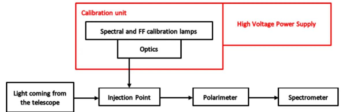
Figure 2.1 shows the block diagram of the calibration unit integrated in the in-strument of Arago.
Figure 2.1: Block Diagram of the calibration unit integrated in the Arago payload.
The calibration unit box includes an Optics box because some optical elements need to be integrated in order to inject an F/13 beam in the optical path of the instrument.
The Spectral and FF calibration lamps box contains calibration lamps needed to cover the requirements exposed in Section 2.3.
The Injection Point box, which is outside the calibration unit, is obviously di-rectly related to calibration. Anticipating the results of the next sections, it is composed of optical elements mounted on a mechanism which inject the optical beam coming from the calibration unit in the optical path of the instrument.
Eventually, there is also a high voltage power supply box in the block diagram. This box is required because of the kind of light sources selected for the calibration unit, again anticipating the next sections.
2.4.2
Calibration Light Sources
2.4.2.1 Flat Field Sources
In order to cover the wide spectral wavelength range of Arago, it is necessary to use several FF calibration sources. The spectral domain is indeed too wide ([119-320] nm and [350-888] nm) to be covered by a single lamp.
The first proposed light source which is able to cover the visible and NIR spectral parts of the Arago instrument is a QTH bulb lamp (concept presented in Section 1.2.2). As it can be seen from Figure 2.2, the relative intensity spectrum is not perfectly flat. The maximum is reached approximately at 600 nm and then the intensity decreases at shorter wavelengths while it remains relatively constant for larger ones. Near 350 nm, the relative intensity becomes lower than one percent of the maximum value. However this kind of lamp is still a very good candidate for the FF calibration between 350 and 888 nm, i.e. over the second part of the Arago spectral domain. If the spectrum of the lamp is well established during the qualifi-cation program, the relative intensity decrease between 350 and 600 nm should not be a problem. Qualifying the output of the calibration lamps and integrating them to the instrument to verify the entire chain is obviously a part of the development program in such ambitious projects.
Figure 2.2: QTH bulb spectrum of a commercial lamp from Thorlabs [24].
Moreover, QTH lamps have already a space mission’s heritage. Indeed, the SCIA-MACHY instrument on the ENVISAT satellite (operational from 2002 to 2012) used QTH lamps for its in-flight calibration. SCIAMACHY was an imaging spectrometer performing global measurements of trace gases in the troposphere and the strato-sphere. It was working over a wider spectral domain than Arago, from 240 to 1700 nm and in selected regions between 2000 and 2400 nm [25]. The calibrating module of UVN (see Section 1.1.2.2) is also using QTH bulbs from Welch Allyn for the WLS part. The bulbs are illuminating the integrating sphere which transfers the light to the parabolic mirror mounted in the wheel mechanism. The light is reflected by the mirror into the instrument for calibration.
The second proposed light source, needed for covering the UV spectral domain, is a Deuterium arc lamp. Indeed, Deuterium lamps have their maximum intensity
emission between 150 and 200 nm with a relatively narrow peak. As can be seen from Figure 2.3, the relative intensity spectrum is not perfectly flat as for the case of QTH bulb lamps. The advantage of Deuterium lamps is that they have a strong intensity in the UV from 117 to 170 nm. Beyond this point, intensity is decreasing and drops below one percent of the peak intensity around 260 nm. The fact that the relative intensity is very low between 260 and 320 nm in the instrument operational range is not necessarily an issue considering the throughput of the instrument that will be very high at these wavelengths owing to high optical and detector efficiencies.
Figure 2.3: Deuterium arc lamp spectrum of a commercial lamp from Hama-matsu [26].
As for QTH bulbs, Deuterium lamps have a strong heritage from space missions such as IUE or HST where they were used for FF calibration of COS [27].
2.4.2.2 Wavelength Calibration Source
The most suitable choice for the spectral calibration lamp is a Platinum-Neon (Pt-Ne) HCL. This kind of calibration lamp has the advantages to have a very strong heritage in space missions such as IUE and HST and also to cover the UV spectral domain from 113 to 320 nm with more than 3000 spectral lines [17][18]. In order to cover a wider spectral range with a high density of spectral lines, it is possible to add about 10% of Chromium (Cr) to the cathode. This was done for the STIS instrument on the HST to get a continuous distribution of emission lines over the range 115-800 nm [28]. Figure 2.4 presents, in log scale, a full STIS spectrum of the HCL.
It has to be noted that the spectrum is not limited to 800 nm as it is specified in [28]. Figure 2.4 clearly shows that the spectrum extends at least up to 900 nm, allowing to cover the entire spectral domain of Arago. Since this lamp covers such
Figure 2.4: STIS Pt-Cr-Ne reference spectrum from [29] and [28].
a broad range of wavelengths, it can provide a suitable solution for the wavelength calibration of the full domain of the spectropolarimeter of Arago. The density of spectral lines is somewhat lower in parts of the visible and NIR domains than in the UV domain. However, it has been verified with the Arago consortium that the number of lines over the entire spectral domain is sufficient to achieve the calibration needs4.
2.4.3
Mechanical Parts
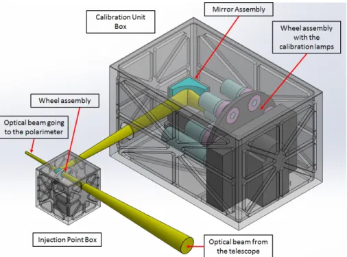
Figure 2.5 presents the 3D overview of the calibration unit box and its injection point box as it should be integrated in the optical path of the Arago instrument. The parts composing these boxes are discussed in the following sub-sections. 2.4.3.1 Calibration Unit Box
The calibration unit box is composed of two main assemblies: a wheel assembly carrying the calibration light sources and a mirror assembly.
The first element is the Lamp Wheel Assembly (LWA, Figure 2.6). The cali-bration lamps are mounted on a mechanism in order to be able to select them for different calibration modes. This design choice results from the fact that several light sources are used, two for FF and one for wavelength calibration, and that it is neither possible nor meaningful to use them simultaneously. There are three iden-tified calibration modes: visible and NIR FF calibration using the QTH bulb lamp, UV FF calibration using the Deuterium arc lamp and wavelength calibration using the Pt-Cr-Ne HCL. Each lamp is mounted on the wheel with a redundant version in case of breakdown or unexpected degradation. At this preliminary stage of the 4It was also mentioned in the proposal of Arago for M5 that a more classical Thorium-Argon
Figure 2.5: Overview of the Calibration Unit Box and the Injection Point Box preliminary designs for the Arago instrument.
design, it is not possible to affirm that a single redundant lamp for each kind of lamp is sufficient or if a second redundant element is needed.
Figure 2.6: Overview of the LWA which is placed inside the calibration unit box. It is composed of a mechanical body on which a stepper motor is mounted. The motor is connected to a wheel part on which the calibration lamps are placed.
The use of an integrating sphere connected to all the light sources was also stud-ied during the proposal preparation. The advantage of such devices is that they prevent the use of a wheel mechanism which is complex and also defined as a single point of failure, hence is critical. However, after some contacts with manufacturers such as Spectralon, it was found that the use of these spheres at wavelengths below 180 nm is not possible because of the reflectivity of the coatings that decreases in this spectral domain. Because of the very large number of reflections occurring in-side the sphere, the losses become prohibitive.
The second element is the mirror assembly which is positioned in front of the LWA. The mirror is used to reflect the light from the lamp which is positioned in front of it for the calibration. The light is reflected in the direction of the injection point box which is placed in the optical path of the Arago instrument.
2.4.3.2 Injection Point Box
The injection point box main element is a small wheel assembly which has three distinct positions (Figure 2.7)
Figure 2.7: Overview of the Wheel Assembly which is placed inside the injection point box. The design is relatively similar to that of the LWA.
The three positions of the wheel assembly are the following:
• Mirror position: the injection mirror is placed in the optical path and the light from the calibration unit box is reaching its surface. The light from the calibration sources is reflected by the injection mirror to the direction of the polarimeter of the instrument. The association of the two mirrors of the
calibration unit should be designed to recreate an optical beam with an f-number similar to that of the telescope of Arago. For this purpose, a simple association of elliptical mirrors is sufficient. Some special care will be needed during pre-flight on-ground calibration to establish the Mueller matrices of the combination of the mirror assembly and the injection mirror as the reflection on these mirrors will introduce instrumental polarization into the light of the calibration sources.
• Shutter position: a shutter is placed in the optical path and prevents the light from the sky to reach the detection chains and allows performing dark calibration. The lamps from the calibration unit box are then assumed to be in an off state.
• Free position: nothing is placed in the optical path and the light from the sky is reaching the polarimeter and the detection chains. This is the observing mode. The lamps are also assumed to be off in this configuration.
It has to be noted that in case of failure of the drive of the wheel, the light from scientific targets have to go through the injection point box. It means that the natural position of the wheel should correspond to the free position and that it must always come back to this position when the system is not controlled.
2.4.4
Power Supply Considerations
The calibration unit is designed for working with several HCL. These lamps are working with high voltage current as it can be seen in [17]. Typically, a HCL needs about 300 V and 10 mA for ignition and 200 V and 10 mA for steady-state operation. The main electronics of the Arago satellite, however, is designed to provide all the systems with a voltage of only 28 V which is obviously not enough for the cali-bration unit. This situation imposes the definition of a power supply box dedicated to the calibration unit.
Referring to [30], there are three ways of packaging high voltage assemblies in instruments: solid potting, conformal coating and completely bare. Each of these packaging have several advantages and disadvantages. For example, the solid pot-ting packaging is very well insulated and is then protected from contamination and external electromagnetic fields but it is heavier than the other solutions.
In this specific case, the power supply can be made of a transformer powered by the main electronics of the satellite and converting the low voltage (28 V) into high voltage (200-300 V). Indeed, the principle of an ideal transformer is the following (Figure 2.8): A magnetic core is used to couple the primary and secondary circuits. An AC electrical current in the primary winding (red part in Figure 2.8) creates a varying magnetic flux in the core which affects the secondary winding (blue part in Figure 2.8). Therefore it induces an alternative voltage in the secondary winding.
Combining Faraday’s law and the energy conservation, it is possible to write for the ideal system: VS = VP ∗ IP IS = VP ∗ NS NP (2.1) In Equation 2.1, V , I and N stand for the voltage, the current and the number of winding turns in the primary (index p) and secondary (index s) windings (Figure 2.8). Using the adequate ratio NS
NP
, it is thus easy to convert the 28 V input from the main electronics in a suitable voltage for the lamps.
Figure 2.8: Ideal electrical transformer principle [31].
In a real transformer, some effects such as hysteresis, Joule losses and leakage flux have to be considered. Therefore, the efficiency of a real system is not 100% but according to [31], it usually reaches 90%.
Due to magnetic effects, the system should be isolated from the other parts of Arago’s instrument and electronics. A suitable shielding should be designed to insulate the transformer part, which would increase the weight significantly. As a consequence, the solid potting packaging seems to be the best solution despite its larger weight. Bever et al. [30] gives a lot of advice and precautions to take to design such space components, as well as the tests necessary to qualify them.
Part II
Very Small Missions Feasibility
Studies
Chapter 3
Cubesats Missions
3.1
Cubesat Standard
3.1.1
Overview
The Cubesat standard has been proposed in 1999 as a collaborative effort between Prof. Jordi Puig-Suari at California Polytechnic State University (Cal Poly), San Luis Obispo, and Prof. Bob Twiggs at Stanford University’s Space Systems Devel-opment Laboratory (SSDL) [6]. The goal is to have at hand a standardization of very small satellite platforms in order to reduce costs and development time and increase accessibility to space while involving students in the development of space projects.
A Cubesat unit is a 10 cm cube with a mass up to 1.33 kg and should be compli-ant with the specifications of [6]. Since the beginning of the standard in 1999, many Cubesat developers have emerged and propose standardized platforms and sub-units such as computer, solar panels, communication systems and so on. They propose a wide variety of solutions that, for a large part of them, already have a space heritage. It is also interesting to note that Cubesats have their own standardized orbit de-ployer which is called the Poly Picosatellite Orbit Dede-ployer (P-POD), designed by Cal Poly. Figure 3.1 shows an overview of a P-POD and a three-unit Cubesat that should be mounted inside the P-POD before launch. The P-POD is a rectangular box with a door and a spring mechanism that, when activated, eject the Cubesat outside the box. The design of a Cubesat satellite should also be compatible with the P-POD design in order to ensure safety and success of the mission [6].
Figure 3.1: Overview of a P-POD and a three-unit (3U) Cubesat [6].
3.1.2
Interests for Cubesats
Cubesats are used for four main purposes [32]:
• Education: Because of the lower costs and the relatively easy access to launches, Universities all over the world have encouraged students to invest their master and PhD theses in research work on Cubesats designs, with dif-ferent and varied purposes. This thesis is one example of this objective while the OUFTI-1 satellite, built at the University of Li`ege by students who worked on the project from 2008 to 2016 for their master theses, is another one. • Technology Demonstration: The low cost of Cubesats, the less rigid risk
management and the relatively short development time are also an advantage for research centers of industrials that want to test a new technology concept, like a specific mechanism or instrument. It has to be noticed that for large space missions, the risks have to be minimized. With that philosophy in mind, it is quasi impossible now to introduce new technologies on large missions because any malfunctioning or failure will cost a huge amount of money to the space agencies. Before the introduction of a new concept, we thus have to rise its Technology Readiness Level (TRL) to make it possible to fly on a satellite. A low cost Cubesat mission is perfect for rising TRLs of new concepts. • Science: This third point can be easily related to the two previous ones. Since
the beginning of the standard, many scientific Cubesats have been launched and operated. Some of them were designed by students, some had scientific objectives, some tested new technologies, or a combination of those [32]. • Communications: This last point is the least abundant in the field of
Cube-sats because the size of the platforms is usually not sufficient to compete with the large communications satellites that come from industry. However, accord-ing to the list of Cubesats missions of [32], a few communication Cubesats were
launched mostly for amateur radio service.
The purpose of the next chapters is to present feasibility studies of Cubesat systems designed for astronomical observations. These are thus all related to the third point of the list, science. Eventually, in Chapter 5 a new concept of polarimeter that has never been used in any space instrument will be presented. The purpose of this latter research is to demonstrate that this polarimeter can be accommodated on a small satellite in order to test it in-flight and rise its TRL. The technology demonstration aspect is therefore also under consideration, along with the education purpose since this work is part of a thesis.
3.2
Cubesats in Astronomy and Astrophysics
It appears from [32] that most of the Cubesats launched until 2013 that had a scientific purpose were intended for Earth observation. This trend is confirmed in [33] and [34], where we can see that Cubesats have not been used so much for as-tronomy and astrophysics. To give an example: according to [34], between 2013 and 2017 NASA sponsored 104 Cubesats in which only one is devoted to astrophysics: HaloSat (still under development, see Section 3.2.3.1).
This section is dedicated to the presentation of past or present successful astro-physics missions using Cubesats platforms and other ones that are currently in their final phases of conception or planned to be developed.
3.2.1
BRITE
BRITE is the acronym for BRIght Target Explorer. It is a constellation of nanosatellites which are designed for astrophysical research, resulting from a collab-oration between universities from Austria, Canada and Poland [9][35]. Six satellites were launched between 2013 and 2014 and five of them are operating, performing precise optical photometry of the brightest stars in the sky. The sixth one did not detach from its launcher.
Figure 3.2 presents an overview of the BRITE satellites structure. The Cubesats of the BRITE constellation are composed of eight units (8U, 20 × 20 × 20 cm). Fig-ure 3.2a shows an exploded view of the satellite with its key components labelled. We can notably see in the interior of the satellite the On-board Computers part for the control of the system, the optical payload and some sensors (star tracker and sun sensors) and reaction wheels for the attitude control. The exterior is composed of panels on which solar panels are placed for the power supply and several antennas are also integrated for the communication with the ground stations. Figure 3.2b shows a picture of one of the BRITE constellation’s fully integrated satellite before launch. The instrument on-board the satellites is an optical photometer composed of several lenses that focus the light onto a CCD detector [35]. As it is explained in
(a) Schematic overview of the BRITE satellites struc-ture with the key components labelled [35].
(b) Picture of one of the satellite from the BRITE constellation [36].
Figure 3.2: Overview of the BRITE satellite structure.
[35], the detector is not cooled by any means and therefore its operational temper-ature is around 20◦C, which is very high for this kind of detector. Indeed, CCDs are subject to several noises such as the dark current which increases with temper-ature. Other space missions using these detectors control the temperature of their detectors in order to have them at -40◦C or below. This way, the data acquisition is more efficient and the scientific results are improved. However, according to [35], the results of the BRITE mission are meeting the mission requirements and are very encouraging for the future of astrophysics with Cubesats.
It has to be noted that the BRITE satellites are the first Cubesats launched and operated with an astrophysical purpose (the observation of stars) as the prime ob-jective. The BRITE constellation demonstrates that it is possible to achieve precise astrophysics objectives with very small satellites and for a limited cost. In addition, the problems encountered by the satellites of the constellation that are reported by the project teams [35] allow new projects to be able to anticipate certain issues. For instance, we can mention the problem of radiation which degrades the detec-tor. The satellites of the constellation are operating in Low Earth Orbit (LEO) and thus are exposed to energetic protons and electrons trapped in the magnetosphere. These particles can cause damage to electronics, memory and CCD detectors. The degradation of the CCDs was a very important problem that required monitoring during the mission. The degradation of the instrument response was mitigated by implementing a chopping observing mode. In this mode, the instrument observes a certain portion of the sky and performs successive exposures while offsetting the telescope pointing back and forth. Then, the two offset frames are subtracted and
![Figure 1.1: Picture of the calibration assembly of the OLCI instrument integrated in the CSL clean room [12].](https://thumb-eu.123doks.com/thumbv2/123doknet/6349243.167432/25.892.278.616.125.399/figure-picture-calibration-assembly-olci-instrument-integrated-clean.webp)
![Figure 2.3: Deuterium arc lamp spectrum of a commercial lamp from Hama- Hama-matsu [26].](https://thumb-eu.123doks.com/thumbv2/123doknet/6349243.167432/39.892.250.625.340.650/figure-deuterium-lamp-spectrum-commercial-hama-hama-matsu.webp)
![Figure 3.5: The ASTERIA telescope optics being integrated and aligned in the laboratory [39].](https://thumb-eu.123doks.com/thumbv2/123doknet/6349243.167432/52.892.297.594.514.906/figure-asteria-telescope-optics-integrated-aligned-laboratory.webp)
![Figure 3.6: The PicSat satellite after integration and qualification at the Paris Observatory [42].](https://thumb-eu.123doks.com/thumbv2/123doknet/6349243.167432/53.892.319.572.500.874/figure-picsat-satellite-integration-qualification-paris-observatory.webp)