HAL Id: hal-02352933
https://hal.archives-ouvertes.fr/hal-02352933
Submitted on 7 Nov 2019HAL is a multi-disciplinary open access archive for the deposit and dissemination of sci-entific research documents, whether they are pub-lished or not. The documents may come from teaching and research institutions in France or abroad, or from public or private research centers.
L’archive ouverte pluridisciplinaire HAL, est destinée au dépôt et à la diffusion de documents scientifiques de niveau recherche, publiés ou non, émanant des établissements d’enseignement et de recherche français ou étrangers, des laboratoires publics ou privés.
ICE SLURRY PRODUCTION IN A TUBULAR HEAT
EXCHANGER
A. Le Bail, Michel Havet
To cite this version:
A. Le Bail, Michel Havet. ICE SLURRY PRODUCTION IN A TUBULAR HEAT EXCHANGER. 24th IIR International Congress of Refrigeration, Aug 2015, Yokohama, Japan. �hal-02352933�
ICE SLURRY PRODUCTION IN A
TUBULAR HEAT EXCHANGER.
A. LE BAIL & M. HAVET,
LUNAM University, Nantes, France
ONIRIS, UMR 6144 GEPEA, CS 82225, 44322 Nantes Cedex 3.
CNRS, Nantes, F-44307, France
Rue de la Géraudière BP 82225, F-44322 Nantes Cedex 03, FRANCE
Fax : 33(0)2 51 78 54 54 67,
alain.lebail@oniris-nantes.frABSTRACT
One of the challenges of ice slurry generation using a heat exchanger is to overcome the risk of choking. The nucleation usually appears after a supercooling state that remains a key aspect of this technology. In order to focus on this crucial problem, the crystallization of a water ethanol solution was studied in a transparent tubular heat exchanger. Our experiments consisted in cooling the solution until ice slurry formation. Flow visualization permitted mainly to determine the conditions of crystallization according to the flow rate. A limited range of flow rate permitted to obtain the desired ice slurry quality. The heterogeneous crystallization appeared on the wall and dendrites began to develop before being carried away by the solution. Experiments also indicated that dendrites growth from the freezing front upstream in the counter flow direction. The velocity of this retro-propagation phenomenon was estimated using an image analysis tool. Temperature measurements also provided important information on this retro-propagation. Selected process parameters have to be properly adjusted (flow rate, wall properties …). This technology has been patented by the CNRS in selected European countries and in the USA.
1. INTRODUCTION
This paper is based on previous presentations done at the IIR congress in Bejing 2007 and during the Ice slurries conference held in Sofia-Bulgaria in 2010. The production of ice slurry attracts a lot of interest due to their interest as secondary refrigerant with a high specific energy and reduced temperature shift over the melting domain. However, there is still a lack of reliable ice slurry generator technology. As mentioned by Egolf (2005), generators using supercooled aqueous solutions with nucleation represent an interesting approach as there do not have mechanical parts. In this kind of generator, the mother solution is first refrigerated until a supercooling state. Then nucleation is initialized with different methods such as momentum decrease, or ultrasonic field as proposed by Inada et al. (2001). The control of ice crystallization and therefore of the supercooling remains the challenge of this kind of generator. Research effort is still necessary in order to get a better understanding on all the phenomena involved in crystallization of aqueous solutions during their cooling in a tubular heat exchanger. Our group has developed a concept of ice generator based on a tubular heat exchanger. The concept has been patented by the French National Council for Research in France, and at follow in selected countries in Europe and in the world (the patent is still under evaluation in USA and in Japan). Gilpin has studied water crystallization in pipes, taking into account the impact of selected flow regimes. For stagnant water, Gilpin (1976) showed that a rate of ice of 5% issued from a dendritic crystallization was enough to block the flow. Gilpin (1980, 1981a) further investigated ice formation in pipes for Reynolds number ranging from 370 to 4000. He obtained wavy annular ice. The variation of the ice thickness was linked to the contraction of the flowing section due to the radial freezing front advance. He concluded that heat transfer between at the freezing front were locally enhanced and led to ice melting. Gilpin (1981b) finally look at the different stages that occurred during the filling of a cold tube by water. He could distinguish three kind of crystallization: the dendritic crystallization, the annular crystallization and the mixed crystallization. This last one corresponds to the formation of dendrites at the walls followed by a fine annular ice layer and by dendrites carried away by the flow. According to the Reynolds number and the wall temperature, it could lead to a blockage of the flow. Inaba and Won (1998)
obtained similar conclusions on the conditions of ice formation. The extrapolation of these results from tap water to aqueous solutions is not directly possible but the analysis of these previous studies indicate that operating conditions for ice slurry generators using supercooled water with nucleation could be better designed from similar experiments.
An important issue concerns the impact of the roughness of the surface on the degree of supercooling. It has been shown by Faucheux et al (2006-a and 2006-b) that the roughness of a surface has a big impact on the degree of supercooling. This is predicted by the theory and has been clearly shown with and experimental study done by these authors. The concept of the patent proposed by Le-Bail (2004) is based on a modulation of the roughness of the surface in a tubular heat exchanger. The tubular heat exchanger is divided in 3 parts. In the first part, a low roughness surface is arranged in the inner part of the pipe in which the fluid to be frozen is circulating. Then, the roughness is increased to promote the crystallisation of the supercooled fluid. If the supercooling is high enough and if the cross section of the flow is properly adjusted, a partial shocking of the flow occurs. Then the down stream flow will establish with a possible increase of the ice ratio.
The purpose of this paper is to present a study on the crystallization of an aqueous ethanol solution (3.5% w/w) in a transparent tubular heat exchanger in order to get a better understanding of the phenomena under different conditions of temperature and flow rate.
2. MATERIALS AND METHODS
A transparent tubular heat exchanger has been constructed and is shown in Figure 1. A central tube made of transparent PMMA (polymethylmethacrylate) with internal and external radii of respectively 4 mm (Rint) and
6 mm (Rext) is installed in a concentric tube of PMMA (internal radius: 20 mm) closed by plastic stoppers.
The length of the system is 75 cm (see Faucheux et al, 2007 for more details). Two connections allow the circulation of a transparency refrigerant around the internal tube. Baffles has been installed to increase the heat exchange between the primary refrigerant and the internal tube.
Figure 1. Cross section of the experimental transparent tubular heat exhanger
A transparent refrigerant (Polydiméthysiloxane) was used as a refrigeration media. It was circulated in a temperature controlled bath (THERMAL HY -JULABO - Germany). A water ethanol solution (3.5% w/w) was used for the tests. It was pre-cooled at a temperature close to its theoretical freezing temperature (Tf
=-1.7°C). The flow of the water/ethanol solution was ensured by a peristaltic pump (Master-Flex easy load II Model 77200-62, COLE-PARMER, USA) that permitted to operate between 10 and 180 ml.min-1. The visualization of crystallization was made using a video recorder (SONY mini DV DRC-PC120E PAL) located at the top of the apparatus. The internal tube in which the aqueous ethanol solution flowed was instrumented with 15 thermocouples (K type) regularly distributed on the centerline. While the aqueous solution was flowing in the internal tube, the experiment consisted in slowly decreasing the temperature of the refrigerant until crystallization started.
Refrigerant (Outlet)
Refrigerant (Inlet)
Ice slurry
(Outlet)
Aqueous
ethanol
solution
(Inlet)
PMMA Central Tube
The internal roughness of the tube was expected to be quite low but has not been determined. Faucheux et al (2006-a and 2006-b) showed that the degree of supercooling was function of the roughness with a power law. With 3 µm roughness, supercooling of up to 12°C can be expected. It was assumed that such a roughness was existing on the internal surface of the tube. In this case, the supercooling is sufficient to provoke a “soft” shocking of the flow, which will not create sticking of ice on the wall of the tube.
3. RESULTS
3.1. Flow visualizationIce slurry production was obtained for flow rates of solution ranging between 18 and 70 ml.min-1 (19 <Re<74). Beyond this range of flow rates, either the flow stopped instantaneously as first crystals appeared, or a fine layer of annular developed until it blocked the flow. In the range of flow rates giving place to a continuous ice slurry production, visualization enabled to analyze the crystallization phenomena. During a typical experiment, heterogeneous crystallization always started at the wall at a location in x-direction that depended on the flow rate of the solution. In the majority of the cases, crystallization started well before the exit of the tube at a place where supercooling was sufficient to allow nucleation. This simply implied that there was a crystallized zone at a temperature close to the theoretical freezing temperature surrounded upstream and downstream by a supercooled solution (Figure 2).
The upstream supercooled zone existed until the first crystals reached the exhaust of the tube. The crystallized zone increased also due to the dendrites that developed upstream in the direction of the negative temperature gradients. As the solution that arrived at the freezing front (x=x1) was colder than the crystals
being downstream, this freezing front tended to move in counter flow direction. We considered this as a retro-propagation phenomenon.
The ice slurry production can be divided in two stages; (i) in a first step, dendritic crystallization appeared at the wall at the freezing front location. Dendrites that grew against the flow direction did not block the cross section. (ii) The second step corresponded to the junction of dendrites diffusing in the radial direction toward the center of the flow and that completely occupied the cross section (kind of chocking). The plug of slurry was viscous enough to be pushed by the main flow as a block of ice slurry and was transported until the exit of the flow in the tube. New dendrites could appear at the wall and a new cycle began. Figure 3 represents a photograph of a bloc of ice being carried away by the flow whereas dendrites grew upstream from the wall.
Figure 2. Scheme of the freezing front advance and of the
temperature repartition along the centreline of the flow (r=0).
X
dendritesx
2T
scT
fx
1T
Downstream supercooling zoner
x
Flow direction Crystallized zone Upstream supercooling zonede surfusion amont
PMMA tube Rint
Figure 3. Obstruction of the flow by ice slurry. The partial freezing of the supercooled flow creates
a sudden obstruction of the flow. The partially frozen flow section is carried away by the flow.
The upstream retro-propagation of the freezing zone results in a continuous ice slurry production. The upstream shift of the freezing front finally stabilized after some time in a zone in the exchanger where the solution is only partially in a supercooled stage (Figure 4). The condition of the surface (roughness), the initial temperature of the flow and the flow rate are the key parameters to adjust. Dendrites could not grow in this zone where the temperature of the solution is higher than the freezing temperature Tf. It is important tohave a large enough supercooling, otherwise dendrites will appear on the wall and may stick on the wall of the tube; if they are not carried away by the flow, the cross section will be reduced and the flow velocity will increase. Such a condition must be avoided as it will result in the end in a choking of the tube. However, in our conditions, the retro-propagation phenomenon finally stabilized and located in section starting from the surface of the refrigerated tube. This had two consequences. At first, the annular layer of ice increased regularly in the radial direction and yielded in a partial chocking of the flow. The second consequence was that the mean velocity of the remaining flow located at centre of the tube tends to increase resulting in the production of a refrigerated mother solution containing no ice crystals.
These observations indicate that it is necessary to be able to stop the retro-propagation of the freezing front before this one reaches the zone of partial supercooling. As this zone depends on the nature of the flow, on the surface properties of the materials used and on the properties of the solution; it is not possible to easily locate the freezing front and to control it.
Figure 4. Different supercooling zones in the tube.
r
refrigerant
Flow direction
T>T
fT<T
fPartial supercooling zone Total supercooling zone
dendrites
Flow
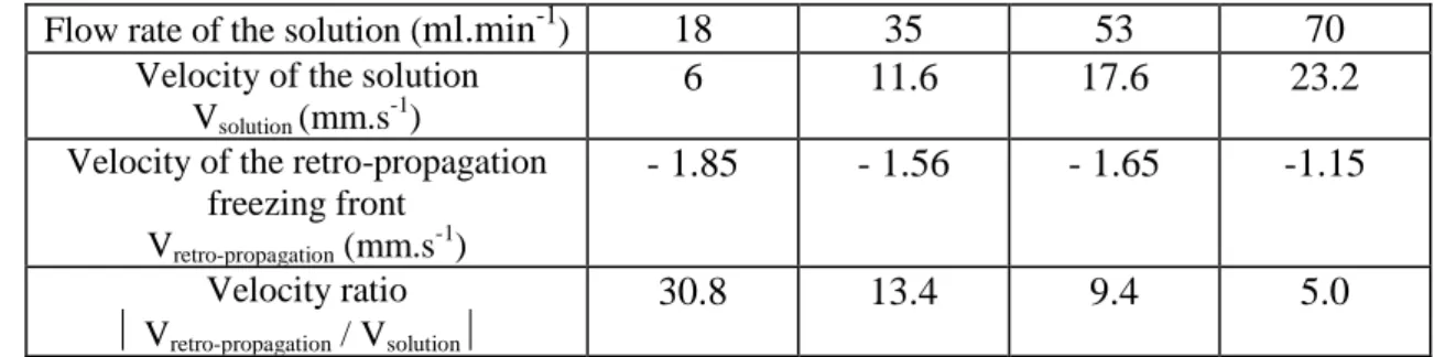
From the videos, we evaluated using an image analysis program (ImageTool) the mean velocity of the retro-propagation front according to the flow rate of the solution (Table 1). It appeared that the phenomenon of retro-propagation of the freezing front is more important for the lower flow rates of the solution.
Table 1.
Mean velocity of the retro-propagation of the crystallization front according to the velocity of the solutionFlow rate of the solution (
ml.min
-1)18
35
53
70
Velocity of the solutionVsolution (mm.s -1
)
6
11.6
17.6
23.2
Velocity of the retro-propagation freezing front Vretro-propagation (mm.s-1)
- 1.85
- 1.56
- 1.65
-1.15
Velocity ratio Vretro-propagation / Vsolution30.8
13.4
9.4
5.0
3.2. Temperature evolutionFrom the thermocouples located every 5 cm in the centerline (r=0), we measured the temperature evolutions during the crystallization. Figure 5 is a typical 3D representation of the evolution of these temperatures with time
in the case of a solution flowing at 53 ml.min
-1. This figure firstly indicates that the solution entered in the tube at a constant temperature close to 3°C. As the theoretical freezing temperature is Tf=-1.7°C, thesolution quickly reached a supercooled stage. It can be seen that a thermocouple located close to the end of the tube (x=0.6 m) recorded the first supercooling release. It provoked downstream and upstream the temperature increase up to the freezing temperature. This phase change plateau clearly appears on this figure.
Figure 5. Temperature evolutions at r=0 (Flow rate of the solution: 53 ml.min
-1)
Similar measurements were obtained for the other flow rates. They confirmed that the greater the velocity of the solution, the less important was the retro-propagation phenomenon. Figure 6 is a synthesis of these results because it represents the supercooling degree (T=Tf-Tsc) measured along the centreline for different
flow conditions. The more important the flow rate, the lower the supercooling degree was. As the ice ratio is directly linked to the supercooling degree, ice slurries produced with the lower flow rate should have a greater ice ratio.
Figure 6. Supercooling degree (
T=T
f-T
sc) measured along the centreline for 4 flow conditions
5. CONCLUSION
Our experimental
investigations concerned the crystallization phenomena during the production of ice slurry in a tubular heat exchanger. We visualized the main physical aspects that governed the nucleation from supercooled water flowing in a tube. A limited range of flow rate permitted to obtain the desired ice slurry production. A too low flow rate led to a rapid dendritic crystal growth that blocked the flow whereas a too high flow rate led to an annular crystallisation. In the intermediate regime, dendritic crystallization appeared on the wall and crystals were carried away by the flow. We also pointed out the retro–propagation of the freezing front in the opposite direction of the flow. This phenomenon, more important at low flow rate, is directly linked to the supercooling degree and to the ice ratio in the slurry. It represents the key point to ensure the continuous ice slurry production in this kind of generator. We actually carry out numerical investigations in order to predict the observed phenomena. Preliminary results are very satisfactory and permit to hope that this model could serve to optimize the parameters (geometry, flow rate, materials …) of further generators.NOMENCLATURE
r, R radius (m) Subscripts
Re Reynolds number (-) ext external
T Temperature (°C) f freezing
x longitudinal axis (m) int internal
sc supercooling