Science Arts & Métiers (SAM)
is an open access repository that collects the work of Arts et Métiers Institute of
Technology researchers and makes it freely available over the web where possible.
This is an author-deposited version published in: https://sam.ensam.eu Handle ID: .http://hdl.handle.net/10985/8736
To cite this version :
Armaghan KHAN, Christophe GIRAUD-AUDINE, Gabriel ABBA, Régis BIGOT - Effects of Vibrations on Metal Forming Process: Analytical Approach and Finite Element Simulations - In: International Conference on Advances in Materials and Processing Technologies (AMPT2010): 24-27 October 2010, Paris, France, France, 2010-10-24 - International Conference on Advances in Materials and Processing Technologies (AMPT2010): 2427 October 2010, Paris, France -2011
Any correspondence concerning this service should be sent to the repository Administrator : archiveouverte@ensam.eu
Effects of Vibrations on Metal Forming Process: Analytical
Approach and Finite Element Simulations
Khan Armaghan
a, Giraud-Audine Christophe
b, Abba Gabriel
aand Bigot Régis
aaLaboratoire de Conception Fabrication Commande (LCFC), Art et Métiers ParisTech, 4 rue Augustin Fresnel,
57078 Metz Cedex 3, France
bLaboratoire de Physique et Mécanique des Matériaux (LPMM), Art et Métiers ParisTech, 4 rue Augustin
Fresnel, 57078 Metz Cedex 3, France
Abstract. Vibration assisted forming is one of the most recent and beneficial technique used to improve forming process.
Effects of vibration on metal forming processes can be attributed to two causes. First, the volume effect links lowering of yield stress with the influence of vibration on the dislocation movement. Second, the surface effect explains lowering of the effective coefficient of friction by periodic reduction contact area. This work is related to vibration assisted forming process in viscoplastic domain. Impact of change in vibration waveform has been analyzed. For this purpose, two analytical models have been developed for two different types of vibration waveforms (sinusoidal and triangular). These models were developed on the basis of Slice method that is used to find out the required forming force for the process. Final relationships show that application of triangular waveform in forming process is more beneficial as compare to sinusoidal vibrations in terms of reduced forming force. Finite Element Method (FEM) based simulations were performed using Forge2008®and these confirmed the results of analytical models. The ratio of vibration speed to upper die speed is a critical factor in the reduction of the forming force.
Keywords: Vibrations assisted forming; visco-plastic domain; analytical model; finite element method (FEM)
INTRODUCTION
Application of vibration during the forming process have been found useful in the recent years. First application of vibration during the forming process was performed in 1953 [1] and since then, many laboratories started using vibration during the plastic forming. Up to now, most of the work done is related to vibration assisted forging, extrusion and wire drawing process. During the research in vibration assisted extrusion process [2], it has been found that if extrusion speed is kept below certain critical speed, then by use of ultrasonic vibrations, extrusion force and material flow stresses can be reduced. The average extrusion force can also be decreased by reducing the extrusion speed or increasing the amplitude of vibration.
Application of ultrasonic-vibration on the dies of tube and wire drawing also reveals reduction of the forming forces, flow stress, friction between die and work-piece, production of better surface qualities and higher precision. Study shows that the extent to which an oscillation may be advantageous depends upon the speed of processing, the type of process, the lubricant used, the mode of oscillation and the material being used [3] and [4].
The study of upsetting a model paste with ultrasonic vibration presents consistent result of compression tests when ultrasonic vibration is superimposed on the static load. During the intervals of superimposed vibration, constant die vibration amplitude of 10µm and frequency of 20kHz were maintained. Applying ultrasonic oscillation results in an immediate drop in the mean forming load [5]. Majority of the work done in analyzing the effect of vibration on forming process is in the range of ultrasonic but the industrial application of ultrasonic vibration is limited by the power rating of ultrasonic generators and low frequencies are usually recommended. Forging with a superimposed vibrational load at 10-40Hz frequency gives a 50 percent increase in deformation and a similar reduction in specific pressure. The tendency of the blank forged to assume a barrel-like shape is also reduced, as a result of which both the stresses and the strains are more uniformly distributed [6].
Researchers have also investigated the upsetting of plasticine [7] and performed the FEM analysis. They prove that if deformation is performed under superimposed vibration, the mean stress necessary to maintain plastic flow decreases in comparison to purely static deformation. According to their study, amplitude has more impact as compare to frequency for mean forming force reduction and also finite element simulations can accurately predict the effects of a superimposed oscillation load on the forming force in upsetting of a elastic-viscoplastic material.
In this work, first, analytical models for vibration assisted forging process will be presented. These models are based on Slice method that will be used for finding out gain in forging force reduction for two vibration waveforms i.e. sinusoidal and triangular. In the second part, the finite element method based simulations for vibration assisted forging process will be presented. Finally, in the third part, the study will be extended to the elasto-viscoplastic domain for vibration assisted forging and extrusion process.
ANALYTICAL MODEL FOR FORGING PROCESS
Slice/Slab Method
In this paper, the classical method known as Slice/slab Method is used for prediction of forging force. This method is used for both forging processes with and without vibrations. This method is easy to apply and is quite simple but capture the influence of friction between the workpiece and die. This method is based on following assumptions:
• Shape of the workpiece will remain same throughout i.e. cylinder remains cylinder and parallelepiped remains
parallelepiped
• No thermal effect will be considered
• Only applicable to viscoplastic domain
The work piece used in this study is cylindrical in shape and forging force required to reduce its height is given by Slice method: F = πD 2σ 0 2A [ 1 A(e A− 1) − 1 ] (1) Here D is diameter of workpiece, A =mD¯h where ¯m is Tresca friction coefficient and h is the height of the workpiece.
The flow stressσ0can be obtained by Norton-Hoff law withσ0= kεnε˙m, k is consistency of material, n and m are
material coefficients. Forging force can be rewritten in terms of function of heightΦ(h(t), which is itself changing with time :
F(t) =Φ(h(t))εn(t) ˙εm(t) (2)
Change in the height of the workpiece with respect to time is h(t) = h0+ v0t + v1(t) and ˙h(t) = v0+ ˙v1(t) where h0is
the initial height of workpiece, v0is mean velocity of die and v1(t) is vibration velocity. Deformation in the direction
of reduction of cylinder’s height is given by:
ε(t) = h0
h(t)− 1 (3)
Deformation rate is given by:
˙
ε(t) =−h0˙h(t)
h2(t) (4)
If there is no vibration:v1= 0 then from Eq. 2, the final expression of the forging force without vibration is given by: F0=Φ(h(t)) [ h0 h(t)− 1 ]n[ −h0v0 h2(t) ]m (5)
Sinusoidal Vibrations
If sinusoidal vibrations are applied then v1(t) = v1cos(2πf t) with amplitude a =2vπ f1 and angular velocityω= 2πf ,
where f is frequency in Hz. For sinusoidal vibrations, the forging force can be found as
Fs=Φ(h(t)) [ h0 h(t)− 1 ]n[ −h0(v0+ v1cos(2πf t)) h2(t) ]m (6)
It is supposed that the functionΦ(h(t)) depends weekly on the sinusoidal vibration. Then the ratio G = Fs/F0is given by: G(t) = [ v0+ v1cos(2πf t) v0 ]m = [1 + R cos(ωt)]m (7)
This equation represents the gain in forging force reduction with R =v1
v0 is the speed ratio. In a particular case of R = 1, final solution obtained is1:
¯
G =−2
mΓ(m + 0.5)
√
πΓ(m + 1) (8)
This equation shows that gain in forging force reduction is only function of sensitivity of strain rate (m) keeping speed ratio R constant.The curve representing this equation is plotted in Fig. 5.
Triangular vibration
Triangular waveform can also be applied in place of sinusoidal. All the equation derived before are valid with some modification for the velocity term (v1) with vibration. For triangular vibration, two velocity terms v+1 and v−1 are
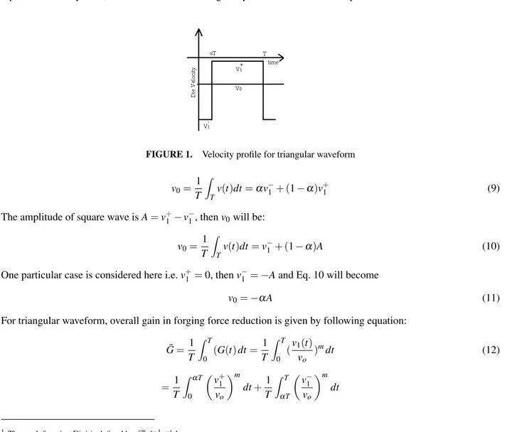
present defining wave (signal) going up velocity and velocity going down velocity as can be seen from Fig. 1. Here,α represents the duty ratio, that is the indication of signal up and down time. Mean speed can be written as:
FIGURE 1. Velocity profile for triangular waveform
v0= 1 T ∫ T v(t)dt =αv−1+ (1−α)v+1 (9)
The amplitude of square wave is A = v+1 − v−1, then v0will be:
v0= 1 T ∫ T v(t)dt = v−1 + (1−α)A (10)
One particular case is considered here i.e. v+1 = 0, then v−1 =−A and Eq. 10 will become
v0=−αA (11)
For triangular waveform, overall gain in forging force reduction is given by following equation: ¯ G = 1 T ∫ T 0 (G(t) dt = 1 T ∫ T 0 (v1(t) vo )mdt (12) = 1 T ∫ αT 0 ( v+1 vo )m dt +1 T ∫ T αT ( v−1 vo )m dt
1 The math functionΓ(x) is defined by∫∞
= ( v+1 vo )m α+ ( v−1 vo )m (1−α) (13)
Putting the values of v0from Eq. 11, the following analytical solution can be obtained:
¯
G =α1−m (14)
This equation shows that gain depends on m (sensitivity of strain rate) if duty ratio is kept constant. Curve for analytical solution of triangular vibrations is shown in Fig (5).
FINITE ELEMENT SIMULATIONS OF FORGING PROCESS WITH VIBRATION
Viscoplastic Domain
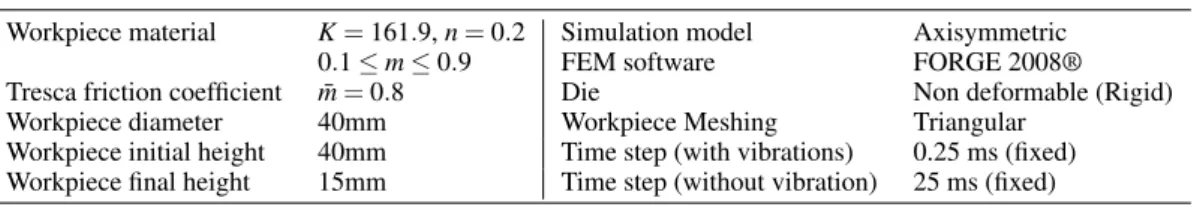
In this section, finite element based software Forge2008®simulations are investigated for forging process. The vibrations are included in the simulations through the routine running behind the simulations. The aim of these simulations is to validate the proposed analytical models. In order to evaluate the influence of the kinematic assumption used to elaborate the model, a purely viscoplastic material is considered, both in the case of sinusoidal and triangular vibration waveforms. The parameters of Norton-Hoff, consistency K and hardening coefficient n of the material were kept constant, while the sensitivity of strain rate m was varied in the range of 0.1 to 0.9 to compare it with the analytical model. Thermal effects were canceled and the friction is modeled using a tresca model with ¯m = 0.8. Table
1 summarizes the different parameters used in these simulations.
TABLE 1. FEM Model parameters used for simulations.
Workpiece material K = 161.9, n = 0.2 Simulation model Axisymmetric
0.1≤ m ≤ 0.9 FEM software FORGE 2008®
Tresca friction coefficient m = 0.8¯ Die Non deformable (Rigid)
Workpiece diameter 40mm Workpiece Meshing Triangular
Workpiece initial height 40mm Time step (with vibrations) 0.25 ms (fixed)
Workpiece final height 15mm Time step (without vibration) 25 ms (fixed)
Fig. 2 shows the model geometry in Forge2008®, where the sinusoidal or the triangular vibration is simulated by the appropriate expression for term v1using a Fortran routine. For all simulations, the upper die speed is constant, v0= 3 mm.s-1. In the case of sinusoidal vibration, the amplitude a is chosen such that aω= v0. Here the trade off was
FIGURE 2. Forging model for upsetting in FORGE 2008 with vibration application
imposed by the software, since enough step per period must be simulated. The choice was to use a frequency f = 40 Hz, and a = 12 µm. Setting a fixed step of 0.25 ms ensures that 100 points per period will be available. The Fig. 3(a) clearly shows the expected effect of forging force reduction with the application of vibrations. In the case of triangular waveform, the waveform is chosen such that the mean speed is 3 mm.s-1, and v+= 0. For this purpose, amplitude is calculated that corresponds to frequency 40Hz and duty ratio 0.1. The calculated value of amplitude is found to be
0 1 2 3 4 5 6 7 8 0 5 10 15 20 25 30 35 40 45 50 Time (sec) Forging force (KN) m=0.1 without vibration m=0.1 with vibration m=0.2 without vibration m=0.2 with vibration m=0.3 without vibration m=0.3with vibration m=0.6 without vibration m=0.6 with vibration m=0.9 without vibration m=0.9 with vibration 0 1 2 3 4 5 6 7 8 0 5 10 15 20 25 30 35 40 45 50 Time (sec) Forging force (KN) m=0.1 without vibration m=0.1 with vibration, duty ratio 0.1 m=0.2 without vibration m=0.3 with vibration, duty ratio 0.1 m=0.3 without vibration m=0.3 with vibration, duty ratio 0.1 m=0.4 without vibration m=0.4 with vibration, duty ratio 0.1
(a) (b)
FIGURE 3. Effect of m on the forging process: (a) with sinusoidal vibration v = 3 mm/s, f = 40 Hz and a = 12 µm, (b) with
triangular vibration v = 3 mm/s, f = 40 Hz and a = 67.6 µm
Elasto-viscoplastic domain
In the context of industrial processes, it is more realistic to consider the elastic behavior as well. It can be expected that the previous results will not apply and that elasticity can mitigate the benefit of vibration. Hence, in this section, without the guidance of a model, the influence of change of different process parameters is studied through simulation. Frequencies and amplitudes will be considered to improve forging process. Table 2 presents data that sum up the parameters used in these simulations. Material and friction coefficients are also mentioned and are kept constant throughout these simulations. The study is limited to sinusoidal vibrations and material used is Aluminium 99.
TABLE 2. Parameters data for forging process
Frequencies f = 40Hz, 60Hz, 80Hz Strain rate sensibility m = 0.3
Amplitudes a = 12µm, 18µm, 24µm Hardening sensibility n = 0.2
Die velocities v0=3mm/s Friction data µ = 0.05, ¯m= 0.1
Material consistency k = 161.9
Fig. 4(a) and (b) presents the reduction ratio of the forging force obtained for the simulations when the frequency and amplitude are varied. All the curves are calculated after filtering the vibrations (using the same filter over 10 periods), and normalising them against the forging force without vibration. Filtering introduces some transient that are noticeable at the beginning and the end of the curves.
0 1 2 3 4 5 6 7 8 0 0.1 0.2 0.3 0.4 0.5 0.6 0.7 0.8 0.9 1 Time(sec)
G (gain in forging force reduction)
40Hz 60Hz 80Hz 0 1 2 3 4 5 6 7 8 0 0.1 0.2 0.3 0.4 0.5 0.6 0.7 0.8 0.9 1 Time (sec)
G (Gain in forging force reduction)
a=12µm a=18µm a=24µm
(a) (b)
FIGURE 4. Forging force reduction ratio : (a) for different frequencies at (v = 3 mm/s, a = 12µm) , (b) for different amplitude at
RESULTS AND DISCUSSION
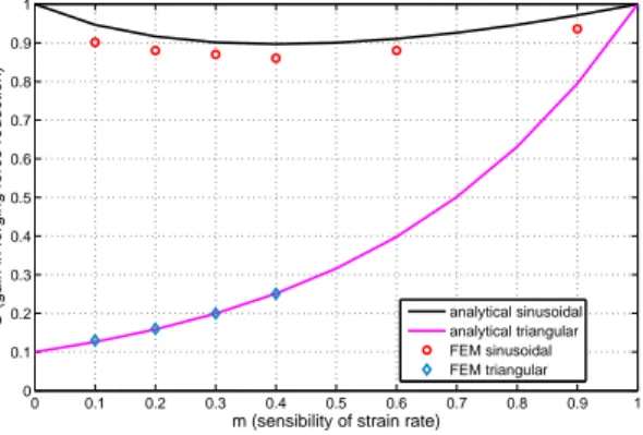
Fig. 5 sums up the results of analytical and simulated gain in force reduction for sinusoidal and triangular waveforms. It can be seen that the correlation between the analytical and simulation models are excellent especially for triangular waveform. In the case of sinusoidal waveform, the simulated results are better than expected. Simulations including temperature and varying the Tresca coefficient were also performed but they are not presented here as no noticeable impact has been found on the results.
0 0.1 0.2 0.3 0.4 0.5 0.6 0.7 0.8 0.9 1 0 0.1 0.2 0.3 0.4 0.5 0.6 0.7 0.8 0.9 1
m (sensibility of strain rate)
G (gain in forging force reduction) analytical sinusoidal
analytical triangular FEM sinusoidal FEM triangular
FIGURE 5. Comparison of analytical models and FE simulations in viscoplastic domain for vibration assisted forging process
The speed ratios corresponding to the frequencies and amplitudes used in Fig.4(a) and (b) are all greater than one ensuring that partial elastic unloading is obtained.The results are worth noticing that there is a reduction in the forging force: as the frequency and amplitude increase (speed ratio increases), the forging force reduces. There would also have been an impact of the friction and temperature however, these hypothesis are still to be investigated.
CONCLUSIONS AND PERSPECTIVE
In this paper, two analytical models have been proposed in the viscoplastic domain. These models are based on a slice model combined with a norton-hoff law. The insight provided by the analytical models was used to identify two important factors, first the speed ratio (the ratio of the die constant speed v0and vibration speed v1) and the
second is the duty ratio (α). Owing to the FEM simulations, the predicted reduction of the forging force has been validated. Based on these models, a triangular waveform has been proposed, that can improve further the benefits of using vibrations.The FEM have been then exploited to explore the potential benefits in the elasto-viscoplastic domain. It was found that vibrations also have a beneficial impact and that the same factor (speed ratio) is relevant. In future works, the analytical model will be extended to direct extrusion.
REFERENCES
1. W.Presz and B.Andersen,Flexible tooling for vibration-assisted microforming, Journal of Achievements in Materials and
Manufacturing Engineering, 21, pp. 61-64, (2007).
2. S.A.A.Mousavi, H.Feizi and R.Madoliat,Investigation on the effects of ultrasonic vibrations in the extrusion process, Journal
of Mechanical Processing Technology, 187-188, pp. 657-661, (2007).
3. M.Hayashi, M.Jin, S.Thipprakmas, M.Murakawa, JC.Hung, YC.Tsai and CH.Hung,Simulation of ultrasonic-vibration
drawing using the finite element method(FEM), Journal of Material Processing Technology, 140, pp. 30-35, (2003).
4. S.Klaus and J.Ulmer,Superimposing Ultrasonics Waves on the Dies in Tube and Wire Drawing, Journal of Engineering
Material Technology, 123, pp. 517-523, (2001).
5. Z.Huang, M.Lucas and MJ.Adams,Influence of ultrasonics on upsetting of a model paste, Ultrasonics, 40, pp. 43-48, (2002).
6. N.V.Polyakov and N.V.Mikhailov,Study of vibration-assisted deformation of metals, Fiziko-Khimicheskaya Mekhanika
Materialov, 2, pp. 482-484, (1966).
7. Z.Huang, M.Lucas and MJ.Adams,Modelling wall boundry conditions in an elasto-viscoplastic material forming process,