Science Arts & Métiers (SAM)
is an open access repository that collects the work of Arts et Métiers Institute of Technology researchers and makes it freely available over the web where possible.
This is an author-deposited version published in: https://sam.ensam.eu Handle ID: .http://hdl.handle.net/10985/9617
To cite this version :
Sofiane DJEBARRI, JeanFrederic CHARPENTIER, Franck SCUILLER, Mohamed BENBOUZID -Design and Performance Analysis of Double Stator Axial Flux PM Generator for Rim Driven Marine Current Turbines - Oceanic Engineering, IEEE Journal of - Vol. PP, n°99, p.8pp - 2015
Any correspondence concerning this service should be sent to the repository Administrator : archiveouverte@ensam.eu
Design and Performance Analysis of Double Stator
Axial Flux PM Generator for Rim Driven Marine
Current Turbines
Sofiane Djebarri, Jean Frédéric Charpentier, Member, IEEE, Franck Scuiller and Mohamed Benbouzid, Senior Member, IEEE
Abstract—This paper deals with the design and performance analysis of double stator axial flux permanent magnet generators for rim-driven marine current turbines (MCT). Indeed for submarine applications, drive train reliability is a key feature to reduce maintenance requirements. Rim-driven direct-drive multi-stator generators can therefore be a very interesting solution to improve this reliability. In this context, the presented work focus on the design of a double-stator axial flux permanent magnets (PM) generator as a rim-driven direct-drive multi-stator generator. The paper details the models, specifications and an optimization procedure that allow to preliminary design these kind of generators for rim-driven marine turbines. Thereafter, validations with finite elements computations and performance analysis considering particular design of rim driven generators are presented. The obtained results highlight some designs issues of PM generators for rim driven marine turbines. In order to assess the effectiveness of the double stator axial flux PM generator, a comparison with a designed surface mounted radial flux PM generator for rim marine turbines is carried out.. The comparison highlights that the double stator axial flux generator presents a better cooling and a reduced active parts cost and mass than the radial flux PM generator.
Index Terms—Marine current turbines, rim-driven, permanent magnets machine, axial flux generators, electromagnetic model, thermal model, immersed gap.
S. Djebarri, J. F. Charpentier and F. Scuiller are with the French Naval Academy, IRENav EA 3634,
29240 Brest Cedex 9, France (e-mail: Sofiane.Djebarri@ecole-navale.fr,
Jean-Frederic.Charpentier@ecole-navale.fr, Franck.Scuiller@ecole-navale.fr).
M.E.H. Benbouzid is with the University of Brest, EA 4325 LBMS, Rue de Kergoat, CS 93837, 29238 Brest Cedex 03, France (e-mail: Mohamed.Benbouzid@univ-brest.fr).
This work was supported by French Navy and ECA-EN Company.
I. INTRODUCTION
Marine renewable energies constitute a very interesting alternative to be combined to other renewable energy sources. Indeed, tidal energy is predictable many years in advance [1-2]. The predictability of tidal currents makes the electrical energy management easier than all other renewable energies. This energy resource allows to limit the visual exposure, the acoustic disturbances and to reduce the environment impacts. However due to the sea immersion, marine tidal power generation requires ultra reliable, salt and waterproof technologies [2-3].
Marine currents kinetic energy can be harnessed using similar technologies as those developed to extract wind energy. This is particularly the case of the firsts developed marine current turbines (MCTs) [4]. Because of tides low speed and to avoid blades cavitations, the turbine rotational speed is typically below 50 rpm. If conventional industrial generators are used, their rated speeds are typically between 1000 and 3000 rpm and multistage gearboxes must be used [5]. Such gearboxes lead to reduce the drive train efficiency and demand high maintenance. This point is particularly penalizing for offshore and underwater technologies. According to literature [6], to make the tidal current energy conversion economically interesting, the MCT should have an approximately 30 years lifespan with maintenance inspections every 5 years. Therefore, MCTs should be highly efficient and reliable.
Direct-drive permanent magnet generators appear as a solution that can fulfill these specific requirements. In direct-drive MCTs, the electrical generator is directly linked to the turbine shaft. This leads to eliminate gearbox and requires the use of low speed generators [7]. In this context, maintenance requirements are significantly reduced and the drive train efficiency is improved. However, the generator active parts mass and cost are expected to be higher if compared with more conventional geared and high speed industrial generators, considering the same rated power.
Regarding MCTs design, with rim-driven topology the generator is placed on the turbine periphery and seems more favorable in term of hydrodynamic behavior than a POD system, where the generator is inserted in a nacelle [8]. Referring to [8], in a rim driven system, the electrical machine volume is less disturbing the water flow. Furthermore, rim-driven technologies naturally imply direct-driven generators and the large generator diameter ensures a reduced active parts mass (in a rim driven system, the internal generator diameter is slightly higher than the turbine blade diameter). As example of industrial rim driven MCT device [4], OpenHydro is probably the most mature technology (fig. 1c). This rim driven turbine has 16 m diameter and 500 kW rated power. It should be pointed-out that the design of such a generator is quite unusual as the active parts are located at the blades periphery (Fig. 1a). Moreover, in previous works of our team a rim-driven MCT demonstrator using a radial flux permanent magnets (RFPM) generator has been designed and tested at the French Naval Academy Research Institute, Brest, France (Fig. 1b) [9-10], the tested rim driven technology has shown an encouraging results.
The presented work has been initiated in [11] and aims to assess the potential of a double stator axial flux permanent magnets (AFPM) generator as a multi-stator generator for a rim-driven MCT technology. Indeed, multi-stator axial flux machines can be interesting solutions for direct-drive turbines. According to literature overview, some MCT and some wind turbines involve axial flux generator technologies [11-12]. C-GEN technology, developed by “Aquamarine Power” company, uses a solution that integrates an air-cored axial generator characterized by a zero cogging torque and high modularity possibilities [13]. In [14], a contra-rotating tidal turbine (CoRMat project) is developed by the University of Strathclyde (Scotland). It includes an axial flux permanent magnets generator. Clean Current Ltd company have also developed marine current turbines based on the use of axial flux generators [15].
(a)
(b) (c)
Fig.1. CAD drawing of rim-driven concept (in this view the electrical machine is an RFPM generator) (a), rim-driven demonstrator that uses a RFPM generator [10] (b), OpenHydro rim driven tidal turbine [4]
(c).
In [16], a modular axial flux permanent magnets generator is proposed for wind turbine applications. In comparison with radial flux machines, axial flux machines could enable a better compactness, a better efficiency [17], and high-speed operation ability [18]. In [19], axial and radial flux permanent magnets machines are compared. According to this study, AFPM machines are suitable if the active length is very short and the pole number is high. Because of high diameter, rim-driven generators are characterized by a
very short active length and high pole number. However in AFPM machines the high electromagnetic axial forces between stator and rotor generates a mechanical stress that can make the manufacturing process particularly hard [20]. In order to reduce these axial forces, multi-stator AFPM machines, ironless stator AFPM machines [21] can be considered. It can also be noticed that multi-stator AFPM machines can be more reliable as, if a fault occurs on one of the stators, the generator can operate at a fraction of the rated power using the remaining healthy stators. Regarding to the presented considerations the design of a double stator AFPM generator for a rim-driven MCT is proposed in this paper.
In this paper, a brief discussion about generator/turbine association is given in section I. In section II, the design specifications of an industrial MCT and the geometry of the proposed double stator axial flux permanent magnets machine are described. This set of specifications will be used to perform the design of a double stator AFPM generator for a rim driven MCT. In section III, the double stator AFPM generator electromagnetic design model is described. It consists of a partially inversed electromagnetic model developed for high diameter and high poles number axial flux machines. In section IV, a lumped parameter thermal model of the generator is established considering particularities related to gap immersion . In section V, the models are associated and the constraints are defined in order to formulate a constrained optimization design problem. This problem is solved considering typical MCT specifications. In section VI, the optimization approach will be used to determine a generator geometry that minimizes the active parts material costs under constraints. Both electromagnetic and thermal finite elements simulations are then performed for validation purposes. In addition, a thermal model sensitivity study has been carried-out to validate the immersed generator thermal modeling. In the last part of this paper (section VII), a classical radial flux surface mounted PM generator is designed using similar models and methodology for the same MCT specifications. This design is then used to compare the RFPM and double stator AFPM generators for rim-driven MCTs.
II. DESIGN FEATURES OF RIM DRIVEN PM MACHINES
A. General design specifications
To carry out a realistic design study, the used specifications are inspired from the Seaflow turbine which is an industrial MCT device. Seaflow has been installed in the north Devon coast of England since 2003 [22]. With 11 m diameter and rotating at 15 rpm for a 2.5 m/sec tidal current velocity developing 300kW rated power. These turbine characteristics are used, in this paper, for the design of PM generators
in a rim-driven context. The configuration of rim driven system implies that the generator internal radius, the mechanical torque, and the electrical generator rated speed, are constrained by the blade geometrical characteristics and the turbine operating point. If the mechanical and viscous losses are neglected, the electromagnetic torque <TEM> of the generator can be considered equal to the turbine mechanical torque Q
as given by relation (1). According to these considerations and to classical design choices of PM generators the given data of table 1 are used for all the studied cases.
EM
T =Q (1)
TABLE 1.DESIGN SPECIFICATIONS SET.
Turbine radius R0 5.5 m
Turbine torque Q 191 kNm
Turbine rated speed N 15 rpm
Tidal current velocity v 2.5 m/s
Magnet pole-arc to pole-pitch ratio βm 0.66 -
Slot fill factor kf 0.65 -
Winding coefficient given at the first harmonic kb1 1 -
Electrical angle between phase electromotive force and phase current
ψ 0 rad
Generator phases number m 3 -
Slot number per pole per phase Spp 1 -
Required generator electrical efficiency ηelecmin 0.9 -
Maximum allowable temperature in slots Tmax 100 °C
Sea water temperature (ambient condition) Twater 30 °C
In order to evaluate the active parts costs and losses, the set specifications are completed by defining the characteristics of the used active parts materials. The data related to the used active parts materials are then given in Table 2. As magnets materials NdFeB magnets are considered for their high energy density, their
high intrinsic coercive field (Hcj > 106 A/m), their high operating temperature, and a low loss of the
residual induction (less than 2% per 10 years [23]), these characteristics makes them suitable to enhance generators reliability particularly for marine turbines where high reliable components are necessary.
TABLE 2.ACTIVE PARTS MATERIAL PROPERTIES.
Magnets (NdFeB) [23]
Residual flux density Br 1.22 T
Intrinsic field coercivity Hcj 1208 kA/m
Operating temperature - Under 100 °C
Relative permeability µrm 1 -
Density ρmagnet 7400 kg/m3
Price [24] Cmagnet 115 $/kg
Standard FeSi iron sheets [25]
Operating frequency felec 50 to 400 Hz
Maximum flux density value where
saturation appears Bsat 1.49 T
Iron sheets thickness - 0.35 mm
Specific iron losses at 50 Hz PFe0 2.5 W/kg
Relative permeability - 5000 -
Thermal conductivity λiron 25 W/m2
Density [26] ρFeSi 7700 kg/m3
Price [27] Ciron 1 $/kg
Copper at 20°C
Electric resistivity ρCu 1.6779×10⁻⁸ Ω.m
Copper equivalent thermal conductivity λCopper 0.8 W/m2
Density ρcopper 8960 kg/m3
Price [24] Ccopper 7.8 $/kg
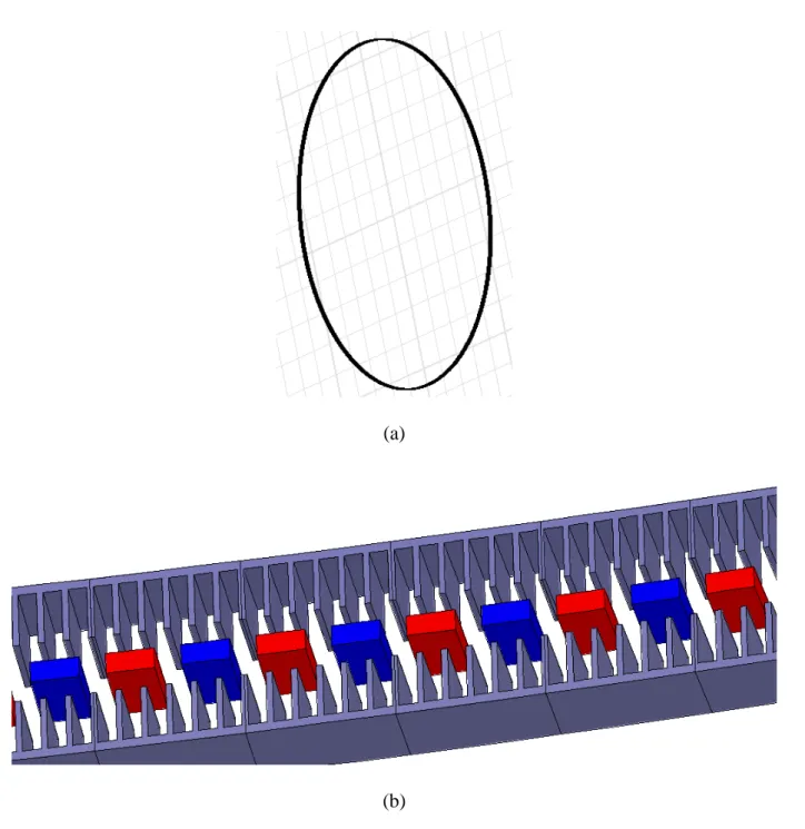
In order to assess the potential of multi stators machines, a double stator AFPM machine is considered. This machine has two discs (stators) that support the windings (Fig. 3). The rotor magnets are mechanically linked to a rim which surrounds the turbine blades. The rotor and the stator surfaces are considered to be covered by a layer of insulating material in order to separate the active parts from seawater (details of the constitution of the stators and rotor are given in the section III and section IV). To reduce the drag on the whole structure, the stators are inserted in a hydrodynamic shaped hull.
(a) (b)
Fig. 3. 3D view of the double stator AFPM machine (a), 3D sketch of the double stator AFPM machine under a pole pairs width (b).
III. ELECTROMAGNETIC MODELING A. Geometrical parameters calculation of the double stator AFPM machine
The electromagnetic topology of an axial flux generator is intrinsically 3D, which makes the electromagnetic modeling more complex. In this paper a simpler approach is considered, where the double stator AFPM generator is assumed to electromagnetically behave as the corresponding linear generator defined at the mean radius (this development is illustrated by Fig. 4). Thereby calculations are done considering the geometry average radius (Rm) as shown in Fig. 3b. This simplification is commonly used
for the modeling of AFPM generators. In the case of rim driven MCT, this assumption on the geometry is particularly realistic because of the very large value of the generator internal diameter (turbine diameter
D = 2R0 exceeds 10 m for high power MCTs turbines) and because of the large number of poles that
characterizes the low speed direct drive generators. Figure 4 illustrates the considered AFPM generator geometry with the corresponding geometrical dimensions defined at the mean radius.
Fig. 4. 2D section of the corresponding linear machine at mean radius: Re, Ri, βt, and βm are respectively
outer and inner radii, teeth pitch ratio, and magnet to pole pitch ratio, Zhm, Zg, Zhs, ZY are respectively the
magnet height, air gap height, slot height and stator yoke thickness.
The other geometrical parameters presented in Fig. 4 can be established by simple geometrical relations, these parameters and simple relations are given in table 3.
TABLE 3.SIMPLE GEOMETRY PARAMETERS DEDUCED BY BASIC GEOMETRICAL RELATIONS.
Inner radius Ri=R0
Radial active length ∆R=Re−Ri
Mean radius Rm=(Ri+Re) / 2
Pole pitch ratio τ = πp /p
Pole pitch width τ = τpRm
The machine is supposed to be supplied with sinusoidal currents. The electromagnetic average torque <TEM> can then be obtained by relation (2).
( )
max 1 3D g 4 2 sin cos 2 EM b L g m m T = k ξ A B S R β π ψ π (2)Where Sg is the air gap area given by Sg = 2πRm∆R, AL is the electrical current load, Bgmax the maximum
air gap flux density. ξ3D is a correction factor that roughly takes into account the magnets three-dimensional flux leakages. The 3D flux leakages mainly depend of the ratio between magnetic air gap (gµ) and the machine active length (Lm) [28]. This correction factor is given by relation (3) that is established
for 0.1< m g L µ < 4. 3D 1 0.2 m g L µ ξ = − (3)
In the case of the considered double stator AFPM generator, 2
g m
h h
gµ = Z +Z andLm = ∆R. Then, the external radius Re of the electrical generator that allowing obtaining the required average electromagnetic
torque for the given Al and Bgmax can be derived from equation (2) by solving equation (4).
( )
max 3 2 3 e 1 3D 0 2 2 sin cos 2 EM 2 i e i e i b L g m T R R R R R R k A B + − − − π = ξ β Ψ (4)It is then obvious that the maximum torque for given Joule losses is obtained by controlling ψ to zero (ψ=0). This control will be considered for the design rated point.
To determine the minimal value of mechanical air gap Zg is defined as the distance between the stator
teeth and the magnets, a coefficient kD is introduced (equation 5).
g D m
This coefficient depends on the structural mass, the electromagnetic stress between the rotor and the iron-cored stator, and several mechanical forces acting on the rotor [20]. According to [21], kD can be
typically set to 10/00 of the mean generator diameter Dm for large direct-drive generators. However rim
driven generators are characterized by higher diameters than conventional direct drive generators, because of that it is suitable to enlarge the kD factor. This factor is considered equal to 20/00 in this study.
For an accurate estimation of magnet height Zhm, a 2D formulation that takes into account the
inter-polar flux leakages is used. Indeed, relation (6) is derived from a 2D model issued from solving the field equations by using the method of separating variables [29]. The calculation is performed considering an equivalent slotless linear generator. The average influence of the slotting effect in the gap permeance is taken into account by considering an additional gap, Zg’.
(
)
( )(
(
)
)
( )(
)
( )(
(
)
)
( ) ' ' max ' ' max 1 1 2 1 1 1 2 1 g g g g g g g g Z Z Z Z rm rm g r rm hm Z Z Z Z rm rm g r rm B e e B Z ln B e e B −π + π + τ τ π + −π + τ τ µ − µ + − − µ + τ = π µ − µ + − − µ + (6)In (6), τ is the pole width (given in table 3 and fig. 4), Zg is the mechanical gap, Br is the magnet residual
flux density, µrm is the relative permeability of magnets. . Relation (7) is valid for open slots generators, it
is used in this study to calculate the additional gap Zg’ [30]. According to [30], (equation (7)) is more
suitable than classical Carter coefficient when the machine magnetic gap is large, which is the case of high diameter rim driven generators.
[
]
' ln( ) (2 ) ln(2 ) 2 s g t t t t Z = τ β β + − β − β π (7)τs is the slot pitch width (see table 3 and fig. 4). To avoid apparition of saturation in the teeth, a
maximum value of the flux density in the soft magnetic materials Bsat is fixed. βt is calculated by assuming
that this level of flux density will be reached in the teeth for the worst case study where the flux density Bgmax created by the magnets and the flux density created by the armature currents at their rated value are
(
)
max 0 ' 2 2 2 g rm L m t sat hm rm g g pp sat B A R B Z Z Z S mpB µ µ π β = + + µ + (8)Where µ0 is the air permeability, Spp is the number of slots per phase per pole (Spp=1 in this study), m is
the phase number (m=3 in this study) and p is the pole pairs number (p is an integer value).
To avoid excessive stator yokes saturation, the minimum yoke thickness ZY is calculated by
considering that the flux density level Bsat where saturation appears is reached in the yokes for the
maximum magnets flux density Bgmax summed to the maximum flux density created by the armature
windings. In a similar way that for establishing equation (8), this calculation is based on the worst case where the stator and rotor flux are in additive configuration (ψ = +π/2). ZY is then determined by relation
(9).
(
)
(
)
max 2 2 0 2 ' 2 2 2 3 2 m g rm L m Y m sat hm rm g g pp sat B A R R Z p B Z Z Z S mp B µ µ π π = β + + µ + (9)For a given set values of the linear electric loading AL (RMS value), the current density in the copper J
(RMS value) and the slot fill factor kf, the equation (10) allows to determine the minimum slot height Zhs.
(1 ) L hs f t A Z k J = −β (10)
C. Magnet field in magnets and electrical efficiency estimations
The maximum magnetic inverse field Hmax in the magnets is evaluated to ensure that demagnetization is
avoided. The expression of Hmax is given in equation (11) for Spp = 1. This expression is established for the
case where the stator and rotor flux are subtractive ones (ψ = -π/2) which corresponds to the worst encountered case during generator operation.
(
)
(
)
(
')
max max 0 ' 2 2 2 2µ g g g m L hm pp hm rm g g Z Z B R A H Z mpS Z Z Z + π = + µ + + (11)By considering the machine Joule losses PJ_tot,andthe iron losses PFe_tot at the turbine rated operating
point (table I), the generator electrical efficiency can be roughly estimated by relation (12).
_ _ 1 J tot Fe tot elec EM P P T + = − Ω
η
(12)IV. THERMAL MODELING A. Thermal network modeling
A lumped parameters model is established to study the steady-state thermal behavior of the stator of the AFPM generator. Only stator copper and iron losses are considered as heat sources in the thermal resistance network model. This thermal model is developed considering heat transfer under a tooth pitch width. Indeed, the heat flows exchanged between slots and teeth are taken into account (2D network). The heat flows pass through the different materials constituting the stator tooth pitch (Fig.5) to be dissipated at last in the stator external sides (gap side and nozzle side). Figure 5 shows a sketch of tooth pitch geometry and the considered heat fluxes. It should be mentioned that only conduction and convection heat transfers are considered. The heat flow is assumed to be fully dissipated to the external sea water area and the immersed gap area in each side of the stator. Furthermore, radial heat transfers and end windings heat losses are not taken into account. Under this hypothesis, the thermal model is a priori more pessimistic than the case where the radial heat transfer is considered.
Frame which insulate the yoke from Sea Water
Sea water (external area of the stator)
z axis x axis
Heat flow Heat flow
Insulation Yoke of the stator
Slot
Sea water in the Air Gap
Half tooth Half tooth Resin T h er m al e x ch an g es b et w ee n t ee th a n d s lo ts
Fig. 5. Considered geometry and heat flows under a slot pitch width.
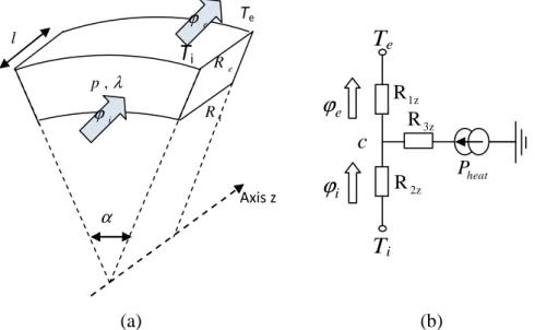
In order to establish the values of the components given in the thermal network model, each portion of material under the slot pitch width has to be modeled. For heat transfer in the axial direction, an elementary material volume is considered as shown in Fig. 6a, this volume is associated with an axial length l, an internal and external radius Ri, and Re, a thermal conductivity λ, and it is subject to a heat
dissipation Pheat. The corresponding thermal modeling is given by Fig. 6b.
α
T
i Te , p λ e ϕ i ϕ l e R i R Axis z iϕ
eϕ
T
eT
ic
1z R 3z R 2z R Pheat (a) (b)Fig. 6. Representation of heat flow exchanges in the axial direction in a portion of material (a), corresponding T scheme thermal modeling (b).
The thermal resistances for Fig. 6b configuration are derived from [31-32] and they can be expressed as given in (13).
(
)
(
)
(
)
1 2 2 2 2 2 3 2 2 3 z e i z e i z e i l R R R l R R R l R R R = λα − = λα − − = λα − (13)For heat transfer calculation in the ortho-radial direction (from slots to teeth), elementary parallelepiped materials volumes are considered to model tooth, slot and the tooth to slot insulation material. These volumes can be defined with a width lx (in the ortho-radial heat flow direction) and a conduction section Scond. The related thermal resistance can then be calculated by (14).
x cond cond l R S = λ (14)
For all the dissipation surfaces (each lateral face of the stators), a convection coefficient hconv and a
convective area Sconv are considered. The convection thermal resistance is given by (15).
1 conv conv conv R h S = (15)
The basic relations (13) to (15) are applied to all the part of the stator. They lead to establish the thermal global network of Fig. 7 that models thermal exchanges occurring under a stator slot pitch (Figure 7 elements are defined in the Appendix).
Twater External environment 12 P 23 P 25 R 15 R' 21 R' 22 R' 23 R' 1 ' ϕ 2 ' ϕ Twater (in the air gap)
11 R' 12 R' 13 R' 14 R' Twater External environment 31 R' 32 R' 33 R' 34 R' 3 ' ϕ Twater
(in the air gap) 1 ϕ 2 ϕ 3 ϕ 14 R R13 R12 R11 21 R 22 R 23 R 24 R 31 R 32 R 33 R 34 R 15 R 12 P' 4
ϕ
23 P' c12 T c23 T 12 T 23 T ct2 R ct1 R cu R 2 isot R 2 cif R 2 fer R 2 12 T' 23 T' c12 T' c23 T' 5ϕ
6ϕ
Fig.7. Thermal network modeling under slot pitch width (slot + tooth).
B. Heat sources
For heat sources calculation, both copper and iron losses in slots, teeth and yoke are considered. For an electrical resistivity ρCu, copper losses can be calculated in each slot as a function of the copper volume per
slot (VCu/slot) and the current density J in the copper.
2
Cu /
=
J Cu slot
P ρ V J (16)
Iron losses PFe (W/kg) can be evaluated in teeth and yoke by the following basic relationship.
0 0 0 b c Fe Fe Fe Fe P P f B f B = (17)
Where f and BFe are respectively the electrical frequency and the iron flux density of the soft magnetic
materials. PFe0 is the iron losses when f = f0 (f0 is the material characteristic frequency). BFeo is the
corresponding characteristic flux density. The values of b and c are set to 1.5 and 2.2 respectively, according to usual soft magnetic materials specifications.
C. Convection coefficients calculation
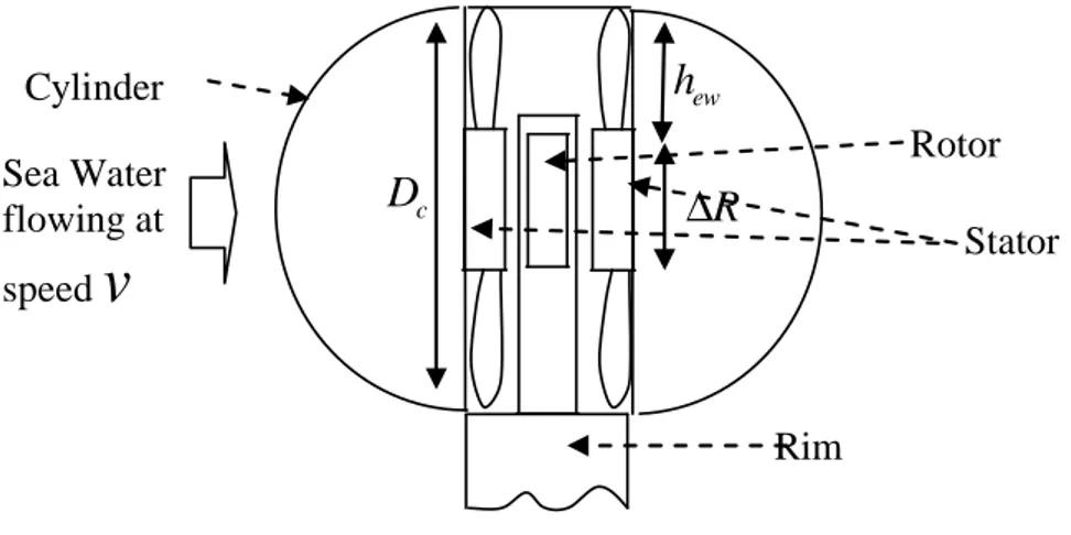
Figure 8 illustrates the hypothesis taken to represent the water flow and the heat transfer between the machine and the sea water. The water flow is supposed to be perpendicular to a cylindrical-shape nozzle in which the double stator AFPM machine active parts are inserted. The sea water convection coefficients can then be evaluated from this nozzle shape assumption and considering an immersed gap. These coefficients depend on the Reynold and Prandlt numbers that characterize the water flow inside the machine (in the immersed gap) and outside the machine (external side of the nozzle).
Stator Sea Water flowing at speed
v
R
∆
ewh
cD
Cylinder Rotor RimFig. 8. Hypothesis of cylindrical shaped nozzle and double stator AFPM machine insertion. Dc is the
cylindrical shaped nozzle and hew is the end windings length.
To calculate the convections coefficients inside the gap and outside the generator some parameters related to the water fluid must be defined. The first specification parameter to be fixed is the sea water temperature Twater. Considering this temperature, the set of following specification parameters are used:
water thermal conductivity λwater (W/m/K), water mass per volume ρwater (kg/m3), water heat capacity Cp
(J/kg/K), and water dynamic viscosity υd (Pa.sec).
For the present study, the sea water temperature is assumed to be equal to 30°C. Considering the above parameters, the thermal diffusivity coefficient a and the water kinematic viscosity υc (m2/sec) can be estimated using relation (18).
water water p d c water a C λ = ρ υ υ = ρ (18)
The Prandlt number can then be estimated by relation (19).
Pr c
a υ
= (19)
For the Reynold number, the gap area and the area located outside the nozzle must be distinguished since the water flows are at different speed. The perpendicular current speed v and the tangential water speed vt (that depends on the rated rotating speed and the generator radius) have to be known to calculate Reynold numbers (relation (20)).
_ _
Outside the nozzle
Re
Re Inside the immersed gap
c c t g eff m g eff c c vD v Z R Z = υ Ω = = υ υ (20)
Where Zgeff is the mechanical gap between the rotor and the stator resin
(Zg eff_ =Zg −Zrotor_resin −Zstator_resin).Zrotor_resinandZstator_resinare respectively the resin thickness covering the magnets and the stator active parts inside the air gap.
Regarding the convection coefficient calculation on the external side of the nozzle, the nozzle is assimilated to a long cylinder. Considering a turbulent fluid flow on the outside nozzle area and only the forced convection, the average Nusselt number can be roughly estimated from relation (21) according to these assumptions.
(
0.5 2 / 3)
0.4Nuoutside = 0.4 Re +0.06 Re Pr (21)
Relation (21) is given for 10 < Re < 105 and 0.67< Pr <300.
The heat transfer convection coefficient is proportional to the Nusselt number Nuoutsideand is calculated by
relation (22). water Nuoutside outside c h D λ = (22)
The convection heat transfer coefficient in the immersed gap is calculated knowing the Nusselt number in the gap area ( Nug) which is given by (23); issued from [33] and takes into account only the forced
convection. It can be noted that with considering only the forced convection the Nusselt number is probably underestimated.
0.68
Nug =0.024 Re (23)
Thus, the convection heat transfer coefficient h in the flooded air gap can be deduced from (24). g
water _ Nug g g eff h Z λ = (24)
V. OPTIMIZATION PROBLEM FORMULATION A. Parameters and design variables
In order to facilitate the distinction between specification parameters and design variables, two specification vectors Sm and St are introduced as illustrated by relation (25). Sm and St components remain constant during the optimization procedure. These two vectors summarize the set of specification related to the materials magnetic properties, the material thermal properties and the fixed geometrical parameters (the value of these data are given in tables1 and 2). An example of Sm and St vectors is given in relation (25). 0 max Cu 0 0 ψ ρ T EM pp m f r sat cj T water Fe Fe water materials water p d
T R m s k B B H T T B P C v = Ω β = λ λ ρ υ m t S S (25)
For the given specification set (Sm and St), the design procedure aims to find a machine that fits as best as possible the objectives and constraints. Using analytical modeling and the study hypotheses, it is possible to fully describe the machine geometry from the knowledge of only four following key design variables: the stator linear electric loading AL (Am-1 rms), the copper current density J (A/mm2) in copper,
the gap flux density Bgmax (T), and the pole pairs number p. These four parameters are the components of
max T L g A J B p = x (26)
Indeed according to the electromagnetic model given in section III, it is possible for a given vector x, to determine a single vector g if the specification vector Sm is known. The scheme of this inversion of the Electromagnetic model is presented at figure 9. The components of g vector are respectively the external radius, Re, the magnet height, Zhm, the slot depth, Zhs, the yoke thickness, ZY, and the teeth width ratio, βt .
These parameters associated with the x and Sm vectors components allow to fully describe the machine
geometry as shown figure 4.
[
]
Te hm hs Y t
R Z Z Z
= β
g (27)
Inverse Electromagnetic Model
Sm St
x
g
Inverse Electromagnetic Model
Sm St
x
g
Fig.9. Electromagnetic model inputs/outputs.
The thermal model described in previous section allows, for a given vector x (and then for known geometrical parameters), to calculate the maximum slot temperature when considering thermal specification vector St. This thermal model will be associated, in the design optimization process to a non linear constraint. This constraint will ensure that the copper operating temperature is lower than the allowed maximal slot temperature Tmax.
B. Optimization procedure
To achieve the generator optimal geometry, an optimization problem is formulated. The optimization variables are the components of the x vector that allow determining the machine geometry given by the vector, g, as explained previously. The optimization objective function aims to minimize the total cost of the machine active parts, here denoted C(x). C(x) is evaluated considering the generator active parts
masses. The active parts masses are determined from knowing the g (deduced from x) and Sm vectors components and from the costs given in Table 2 (relation (28)).
( ) copper( ) copper iron( ) iron magnet( ) magnet
C x =M x C +M x C +M x C (28)
Mi and Ci respectively denote the mass (kg) and the price ($/kg) of each used active parts materials.
To fully define the optimization problem, some constraints must be introduced. The first nonlinear inequality constraint relates to the machine thermal behavior. In fact, the maximal coil temperature must be limited to satisfy the temperature limit that can be supported by the insulation materials in the slots (Tmax), this constraint is given by relation (29). The temperature T(x) is calculated using the thermal model
as presented previously. Another nonlinear inequality constraint limits the magnetic field inside the magnets to avoid their demagnetization, this constraint is introduced by (30). Furthermore, a nonlinear constraint on the minimal electrical efficiency is included to ensure the required electrical efficiency of the optimal generator; this constraint is introduced in the optimization algorithm by relation (31).
max ( ) 0 T x −T ≤ (29) max( ) cj 0 H x − H ≤ (30) min ( ) 0 elec elec −η x + η ≤ (31)
Where T(x) is the thermal model, Hmax(x) is the magnetic model that allows to determine the maximal
magnetic field inside the magnets for each values of the vector x (Hmax(x) is calculated using relation (11)), ηelec(x) is the model function that allow evaluating the electrical efficiency of the generator for a given
variables vector x. Tmax, Hcj and ηelec,min are given in table 1.
Otherwise, a nonlinear constraint related to the pole pair number limitation is added to ensure feasible machine shape. To fulfill the machine shape requirements, a first constraint (pmax1), given by relation
(32),is introduced. This relation relates to the frequency operation limits of the magnetic steel laminations. This condition should be respected to have a realistic estimation of iron losses, given by the utilized iron losses model (given in section III), which is valid in the frequency working range of the iron sheets (table 2). The second constraint is introduced by defining a feasible ratio ℜ (in terms of manufacturing) between the slot heights and the tooth width. The slot shape ratio ℜ is calculated by relation (33).
According to [34] this ratio can be taken in the range ℜ∈[ℜmin,ℜmax] = [4,10], to avoid excessive
mechanical vibrations. From the upper ratio ℜmax, another upper limit (pmax2) for the pole pair number can
be deduced. This second upper limit (pmax2) is given by relation (34). The maximum allowable poles pair
number is then introduced in the optimization process as a constraint by relation (35). Considering the lower ratio ℜmin , a last constraint is introduced that fix a lower limit on the poles pair number (pmin1), is
defined to maintain the ratio ℜ into the interval ℜ∈[4,10] during the optimization process. This constraint is established by equations (36) and (37).
max1
2 felec
p = π
Ω
(32)
Where Ω is the generator rotational speed.
(
)
2 1 2 L pp f t t A pmS k J R × ℜ = −β β × π (33)(
)
max max 2 2 2 1 t pp L f t R mS p A k J π ℜ ×β × = −β (34)(
max1 max 2)
min , 0 p− p p ≤ (35)(
)
min min1 2 2 1 t pp L f t R mS p A k J π ℜ ×β × = −β (36) min1 0 p p − + ≤ (37)At last, upper and lower bounds are introduced as linear constraints to restrict the optimization space and then to obtain feasible solution (relation (38))
( ) ( ) max min max min max min max max max min 2 max 3 L L L g g g A A A J J J LB UB B B B p p p ≤ ≤ ⇔ ≤ ≤ x (38)
These bounds are set to LB = [20000 (A/m), 1 (A/mm2), 0.1 (T), 50 ]T and UB = [150000 (A/m), 10 (A/mm2), 1 (T), 500 ]T.
Relation (39) summarizes the formulation of the optimization problem presented previously:
( )
(
min)
* max max max1 max 2 min1 min ( ) 0 ( ) 0 ( ) 0 min , 0 0 cj elec elec C T T H H p p p p p LB UB ∈ = − ≤ − ≤ −η + η ≤ − ≤ − + ≤ ≤ ≤ x X x x x x x x (39)VI. RESULTS ANALYSIS A. Optimization analysis
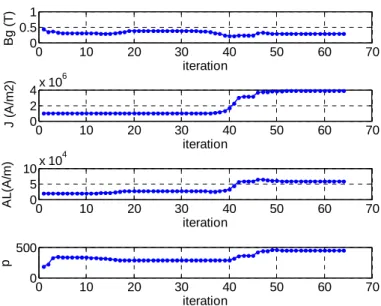
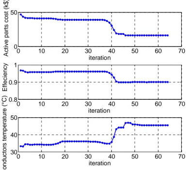
Considering the given specifications of Tables 1 and 2 and the proposed models and methodology the optimization process is performed with SQP (sequential quadratic programming) algorithm. This optimization algorithm is available under MATLAB fmincon function. Figure 10 illustrates the optimization algorithm evolution up-to the optimal solution x* convergence. Figure 11 gives the total active parts cost (objective function), the electrical efficiency and the slots temperature evolution during the optimization iterations.
0 10 20 30 40 50 60 70 0 0.5 1 iteration B g ( T ) 0 10 20 30 40 50 60 70 0 2 4x 10 6 J ( A /m 2 ) iteration 0 10 20 30 40 50 60 70 0 5 10x 10 4 A L (A /m ) iteration 0 10 20 30 40 50 60 70 0 500 p iteration
Fig. 10. Electromagnetic parameters evolution during the optimization iterations.
This figure 11 clearly shows that cost minimization and efficiency decrease are strongly correlated: constraint relating to the efficiency is here first saturated. The other constraints are not saturated: the final conductors temperature is about 45°C (for 100°C allowed) and the final magnetic coercive field is about 0.538 MA/m (for 1.208 MA/m allowed). This clearly shows that the temperature constraint related to the maximum slot temperature (Tmax) cannot be saturated because the electrical efficiency constraint is
saturated first. This is due to the good cooling related to the subsea generator immersion. Furthermore, as it is observed in Fig. 10, when the active parts cost is minimized, the pole pair number p, the current load AL, and the copper current density are increased whereas the air gap flux density created by magnets is
decreased. However, even if increasing AL and J lead to lower active parts cost, these variables cannot be
0 10 20 30 40 50 60 70 0 50 A c ti v e p a rt s c o s t (k $ ) iteration 0 10 20 30 40 50 60 70 0.8 0.9 1 E ff e c ie n c y iteration 0 10 20 30 40 50 60 70 30 40 50 C o n d u c to rs t e m p e ra tu re ( °C ) iteration
Fig. 11. Objective function and main nonlinear constraints evolution during the optimization iterations.
B. Electromagnetic design discussion
The design parameters corresponding to the optimal double stator AFPM machine solution is obtained with the previously described procedure, the obtained optimal machine is summarized in Table 4.
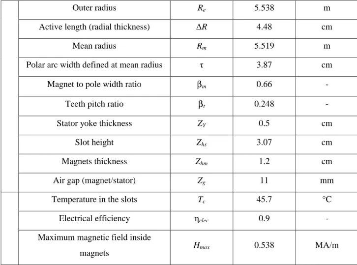
TABLE 4.OPTIMIZED DOUBLE STATOR AFPMGENERATOR GEOMETRY. Double Stator AFPM Generator (300 kW)
*
x
Current density J 3.8 A/m2 (rms)
Stator linear electric loading AL 58078 A/m (rms)
gap flux density Bgmax 0.295 T
Pole pair number p 448 -
*
Outer radius Re 5.538 m
Active length (radial thickness) ∆R 4.48 cm
Mean radius Rm 5.519 m
Polar arc width defined at mean radius τ 3.87 cm
Magnet to pole width ratio βm 0.66 -
Teeth pitch ratio βt 0.248 -
Stator yoke thickness ZY 0.5 cm
Slot height Zhs 3.07 cm
Magnets thickness Zhm 1.2 cm
Air gap (magnet/stator) Zg 11 mm
Temperature in the slots Tc 45.7 °C
Electrical efficiency ηelec 0.9 -
Maximum magnetic field inside
magnets Hmax 0.538 MA/m
Fig. 12a gives a scale drawing of obtained double stator AFPM generator active parts volume. Figure 12b shows a zoom on the active parts drawn at the scale. As expected the resulting double stator AFPM machine is characterized by a thin axial and radial thickness, which complies with the requirements of rim-driven marine turbines [11].
(a)
(b)
Fig. 12. Sized double stator AFPM generator active parts volume representations (a), zoom on a machine arc (b).
For validation purposes, 3D finite elements (FE) computations have been performed for the obtained optimal rim driven generator using Maxwell 3D© software (Fig. 13). In this case, a difference of about 4% is found between calculated electromagnetic torque and the required one which is acceptable at this predesign step. In addition, finite elements calculations also show that the calculated axial machine magnetic circuit is not saturated as illustrated in Fig.13. In fact, saturating the magnetic circuit to reduce iron volume is not an issue for rim drives because the part of the iron mass is not significant compared to
the total marine turbine mass. Furthermore, in this kind of rim driven structures, the electrical generator is characterized by a large magnetic gap and a small machine active length that lead to high 2D and 3D flux leakages.
(a) (b)
Fig.13. Flux density distribution 3D mapping (a), mesh of the double stator AFPM machine under a pole width (b).
C. Thermal model validation and discussion
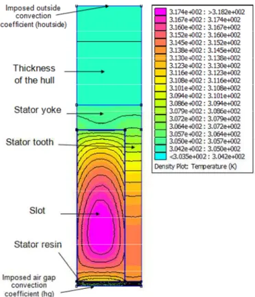
In order to estimate the thermal resistance network model accuracy, a 2D finite elements computation is performed for the final optimal machine geometry. In this case, FEMM software that allows solving the heat transfer equation in steady-state operation is used [35]. Figure 14 shows the obtained temperature mapping under a slot pitch width. The analytical slots temperature evaluated by the lumped parameter model is very close to the one obtained with finite element. The difference is here lower than 1% (45.7°C for the analytical calculation and 45°C for the numerical computation). It should be noted that same heat transfer convection coefficients are introduced in both analytical thermal model and numerical software.
Fig. 14. Temperature mapping under a slot pitch width (finite element computations).
The heat transfer convection coefficients are however issued from basic hydrodynamic formula described in section IV. The accuracy of their estimation is therefore not fully guaranteed. For that purpose, the influence of these coefficients variation on the calculated slots maximal temperature has been studied. Figure 15 gives a mapping of this coils temperature according to the heat transfer convection coefficients values calculated by relations (18 to 24). Figure 15 clearly shows that the convection coefficients variations do not strongly affect the slots maximal temperature. The temperature variation is less than 10% when the outside heat transfer convection coefficient exceeds 600 W/K/m2 (houtside >
600W/K/m2) when the calculated one is 4059 W/K/m2. Indeed, it is related to the large values of the convection coefficients due to the good cooling related to generator immersion in the sea water. In fact, these high values of convection coefficients lead to very small values of convection thermal resistances that can be neglected referring to conduction thermal resistance of the insulation materials. Otherwise, Fig. 15 clearly underlines that the slots temperature is even less sensitive to the air gap heat transfer coefficient (hg).
0 2000 4000 6000 8000 10000 0 5000 10000 35 40 45 50 hg (W/K/m2) houtside (W/K/m2) T m a x ( °C )
Temperature sensitivity in conductors °C
Fig. 15. Sensitivity of the maximal slot temperature versus the convection coefficients variations.
Table 5 gives the machine heat flow repartition between the nozzle external area and the immersed gap. It shows that 25% of the total heat flow produced by the losses is evacuated through the gap and only 5% of the heat flow is exchanged between slots and teeth. The small proportion of heat flow exchanged from slots to teeth is due to the small temperature difference between slots and teeth. However, even if an immersed gap allows a significantly better cooling, the presence of water in the gap leads to additional losses related to water viscosity that are not taken into account by the proposed models. In fact, the considered immersed gap has some advantages and inconvenient that are resumed in table 6.
TABLE 5.EXCHANGED HEAT FLOW PROPORTIONS.
Immersed gap convection coefficient (hg) 4059.4 W/K/m2
Outside convection coefficient (houtside) 5042.6 W/K/m
2
Outside heat flow 10965 W/m2
Heat flow exchanged with the immersed gap 3748.8 W/m2
TABLE 6. QUALITATIVE COMPARISON OF FLOODED AND WATERPROOF AIR GAPS.
advantages inconvenient
Immersed gap
better thermal cooling No use of special nozzle to ensure gap waterproof
Higher viscous losses and frictions in the gap
Need of special fluid bearings Resin inside the gap to cover magnets and stator active parts
Waterproof gap
Less viscous and friction losses
No resin and special fluid bearings in the gap
Reduced gap thermal exchanges Use of reinforced waterproof nozzle
VII. DOUBLE STATOR AFPM AND RFPM MACHINES COMPARISON
The aims of this section is to compare the studied double stator AFPM generator solution with a more conventional solution based on the use of radial flux permanent magnets generator for the same rim-driven specifications. For comparison purposes, a radial flux machine design is performed using a similar methodology and the same specifications as for the double stator AFPM generator. The radial flux generator design procedure implies similar electromagnetic and thermal models. These models have the same level of complexity and accuracy than the ones used to design the axial flux topology.
A. Sizes and active parts comparison
A similar design optimization approach as in section V is carried-out to optimize the RFPM machine with considering the same design specifications. The used RFPM generator is based on classical design options, with surface mounted magnets as shown in Fig.16a. The resulting machine is compared to the previously optimized double stator AFPM generator. Table 7 gives a comparison between the both RFPM and double stator AFPM generators geometry and performances main parameters. In Table 7, the volume dimensions of the two generators (RFPM and double stator AFPM generators) are also presented for comparison purposes. End-windings are included by considering a simple half cylinder end-winding geometry [36]: the end-winding diameter is considered equal to the pole arc width. From Table 7 analysis, the following conclusion can be drawn: a double stator AFPM generator appears to be more compact than
the RFPM generator when considering the active parts volume sizes. However this difference is not really significant because both machines are characterized by very large diameters. Figure 16 shows slots, magnets, and yoke dimensions, of the two optimized generators.
TABLE 7. DOUBLE STATOR AFPM AND RFPMGENERATORS COMPARISON.
RFPM generator Double stator
AFPM generator units
Pole pair number 267 448 -
Inner radius 5.5 5.5 m
Generators radial thickness (with end
windings for the axial generator) 8.2 6.67 cm
Axial length (with end windings for the
radial generator) 13.2 11.74 cm
Magnet thickness 8.6 12 mm
Current density in copper 3.663 3.8 A/mm2 (rms)
Stator linear Electric loading 76981 58078 A/m (rms)
Maximum gap flux density 0.250 0.295 T
Active length 7.3 4.48 cm
Magnet to pole width ratio 0.66 0.66 -
Teeth pitch ratio 0.235 0.248 -
Yoke thickness 2,95 0.5 cm
Slot height 4.23 3.07 cm
gap thickness (magnets to stator distance) 22 11 mm
Maximum temperature in the slots 49.5 45.7 °C
Electrical efficiency 0.9 0.9 -
(a) (b)
Fig. 16. Optimized RFPM generator (Table 7) (a), optimized double stator AFPM generator (Table 4) (b).
According to Fig. 18, the calculated double stator AFPM generator is more compact than the RFPM machine in terms of active parts mass (25% reduction of the active parts mass). Regarding the costs comparison, the double stator AFPM generator presents active parts cost reduction of about 20% (fig. 17). This can be explained by the higher poles number of the double stator AFPM machine (Table 7). Indeed, poles number is higher with the axial machine because the copper volume is distributed over two stators. Then it becomes possible to find a higher pair pole number that matches a feasible tooth shapes (to satisfy the constraint on the tooth shape factor). For both machines, a significant part of copper is used in the end-windings (more than 50% of the total copper volume is in the end end-windings in the both cases). This high volume is due to the small machine active length related to rim-driven generator integration (very high diameter). For the presented costs comparison, the inactive materials are not taken into account. This assumption is justified by the fact that these materials price would be much lower than the price of active materials (permanent magnets and copper) even if the active parts mass is lower than the generator and the MCT turbine structural masses [21].
0 2.5 5 7.5 10 12.5 15 17.5 20 22.5 25 A c ti v e p a rt s c o s ts ( k $ ) RFPM Generator DSAFPM Generator Cost of FeSi iron sheets Cost of magnets (NdFeB) Total active parts costs Cost of Copper
Fig. 17. Comparison of double stator AFPM and RFPM generators active parts costs.
0 200 400 600 800 1000 1200 1400 1600 A c ti v e p a rt s m a s s e s ( k g ) RFPM Generator DSAFPM Generator Mass of copper Total mass of active parts Magnets mass Mass of FeSi iron sheets
B. Thermal behavior comparison
Regarding the thermal behavior of the double stator AFPM machine, the estimated maximal slots temperature is about 45°C whereas the temperature is 49.5°C in the corresponding radial machine (Table 7). This result confirms that the double stator AFPM generator has a better thermal behavior. This is due to the current load distribution on the two stators.
C. Achieved results versus required efficiency
In both axial and radial generators design cases, the constraints on the electrical efficiency are saturated. Therefore, the influence of the minimal electrical efficiency value is studied (Figs. 19 and 20).
Figure 19 gives a Pareto front of the considered objective function (active parts cost function) as a function of the electrical efficiency. It is interesting to note that the Pareto curve shows that the generator electrical efficiency presents two limit values (Fig. 19 curve bounds). The minimal efficiency limit value corresponds to the minimum active parts cost. This lower limit is reached when the temperature constraint is saturated (for an efficiency of 0.9). In this case the current density J in the copper and the stator linear electric loading AL reach their maximum allowable values. According to Fig. 20, the maximal efficiency
limit corresponds to the maximal active parts cost and this upper bound matches the minimal losses (balance between Joule and iron losses). Thus for direct-drive permanent magnet machines the iron losses cannot be neglected when the generator is designed with a maximal electrical efficiency strategy, even if the generator speed is low.
0.4 0.5 0.6 0.7 0.8 0.9 0.98 0 10 20 30 40 50 60 70 80 90 Genrators Efficiency T o ta l c o st o f a c ti v e p a rt s (k $ )
Fig. 19. Pareto front of total cost versus generator efficiency. 40 50 60 70 80 90 97.5 0 20 40 60 80 100 120 Electrical Efficiency (%) L o s s d is tr ib u ti o n ( % ) Copper Losses Iron losses
Copper and iron losses at maximum electrical efficiency of the DSAFPM generator
Fig. 20. Losses distribution versus electrical efficiency.
VIII. CONCLUSION
This paper is devoted to the design and performance analysis of axial flux permanent magnet generators for rim-driven marine current turbines. Thermal and inverse electromagnetic analytical models are described and integrated in an optimal design strategy that allows designing direct drive rim driven AFPM generators. This original strategy aims to minimize the active parts costs and takes into account a minimal efficiency constraint and marine context specifications. The achieved axial flux generator design has been validated by both thermal and magnetic finite elements computations. These computations validate the used analytical models. Results analysis allows underscoring some design issues for rim drives marine turbines generators. Furthermore and for comparison purposes, a radial flux generator has been optimally designed with similar design models and with the same specifications. The comparison of the two topologies mainly shows that the double stator axial flux permanent magnets generator has a lower cost, a lower mass and better cooling performance.
REFERENCES
[1] M. Leijon, H. Bernhoff, M. Berg and O. Agren, “Economical considerations of renewable electric energy production - especially development of wave energy,” Renewable Energy, vol. 28, n°8, pp. 1201-1209, 2003.
[2] S. Benelghali, M.E.H. Benbouzid and J.F. Charpentier, “Marine tidal current electric power generation technology: State of the art and current status,” in Proceedings of the 2007 IEEE IEMDC, Antalya (Turkey), vol. 2, pp. 1407-1412, May 2007.
[3] S. Moury and M.T. Iqbal, “A permanent magnet generator with PCB stator for low speed marine current applications,” in Proceedings of the 2009 IEEE ICDRET, Dakha (Bangladesh), pp. 1-4, December 2009.
[4] http://www.openhydro.com (last accessed, April 2013).
[5] O. Keysan, A.S. McDonald and M. Mueller, “A direct drive permanent magnet generator design for a
tidal current turbine (SeaGen),” in Proceedings of the 2011 IEEE IEMDC, Niagara Falls (Canada), pp. 224-229, May 2011.
[6] R.E. Harris, L. Johanning and J. Wolfram, “Mooring systems for wave energy converters: A review of design issues and choices,” in Proceedings of the 2004 MAREC, Blyth, (UKA), pp. 1-10, July 2004. [7] R.S. Semken, M. Polikarpova, P. Roytta, J. Alexandrova, J. Pyrhonen, J. Nerg, A. Mikkola and J.
Backman, “Direct-drive permanent magnet generators for high-power wind turbines: Benefits and limiting factors,” IET Renewable Power Generation, vol. 6, n°1, pp. 1-8, January 2012.
[8] O. Krovel, R. Nilssen, S. E. Skaar, E. Lovli and N. Sandoy, “ Design of an integrated 100 kW permanent magnet synchronous machine in a prototype thruster for ship propulsion,” in Proceedings of the 2004 ICEM, Krakow (Poland), pp. 1-6, September 2004.
[9] L. Drouen, J.F. Charpentier, E. Semail and S. Clenet, “Investigation on the performances of the electrical generator of a rim-driven marine current turbine,” in Proceedings of the 2008 ICOE, Brest (France), pp. 1-6, October 2008.
[10]L. Drouen, Machines électriques intégrées à des hélices marines, contribution à une modélisation et conception multi-physique, PhD Thesis (in French), Arts & Métiers ParisTech (France), December 2010.
double-stator axial flux permanent magnet generator for a rim-driven marine current turbine,” in Proceedings of the 2012 IEEE ISIE, Hangzhou (China), pp. 1450-1455, May 2012.
[12]J. H. Kim, and B. Sarlioglu, “Preliminary design of axial flux permanent magnet machine for marine current turbine,” in Proceedings of the 2013 IEEE IECON, pp. 3066-3071, November 2013.
[13]O. Keysan, A. McDonald, M. Mueller, R. Doherty and M. Hamilton, “C-GEN, a lightweight direct drive generator for marine energy converters,” in Proceedings of the 2010 IET PEMD, Brighton (UK), pp. 1-6, April 2010.
[14]J. Clarke, G. Connor, A. Grant, C. Johnstone and S. Ordonez-Sanchez, “Analysis of a single point tensioned mooring system for station keeping of a contra-rotating marine current turbine,” IET Renewable Power Generation, vol. 4, n°6, pp. 473-487, November 2010.
[15]http://www.cleancurrent.com (last accessed, April 2013).
[16]E. Muljadi, C. P. Butterfield and Y. Wan, “Axial-flux permanent-magnet generator with a toroidal winding for wind-turbine applications,” IEEE Trans. Industry Applications, vol. 35, n°4, pp. 831-836, July/August 1999.
[17]B.J. Chalmers, W. Wu and E. Spooner, “An axial-flux permanent-magnet generator for a gearless wind energy system,” IEEE Trans. Energy Conversion, vol. 14, n°2, pp. 251-257, June 1999.
[18]M.R. Dubois, H. Polinder and J.A. Ferreira, “Comparison of generator topologies for direct-drive wind turbines,” in Proceedings of the 2000 NORPIE, Aalborg (Denmark), pp. 22-26, June 2000. [19]A. Cavagnino, M. Lazzari, F. Profumo and A. Tenconi, “A comparison between the axial flux and the
radial flux structures for PM synchronous motors,” IEEE Trans. Industry Applications, vol. 38, n°6, pp. 1517-1524, November/December 2002.
[20]M.A. Mueller, A.S. McDonald and D.E. Macpherson, “Structural analysis of low-speed axial-flux permanent-magnet machines,” IEE Proc. Electric Power and Applications, vol. 152, n°6, pp. 1417-1426, November 2005.
[21]A.S. McDonald, M.A. Mueller and H. Polinder, “Structural mass in direct-drive permanent magnet electrical generators,” IET Renewable Power Generation, vol. 2, n°1, pp. 3-15, 2008.
[22]Seaflow, “Pilot project for the exploitation of marine currents,” EU Research Report, EUR 21616, 2005.
[23]T.J.E Miller, Brushless Permanent-Magnet and Reluctance Motor Drives. Oxford Science
Publications, 1989.
[25]J. Degauque, “Matériaux à propriétés magnétiques dures : Matériaux industriels,” Techniques de l’Ingénieur (in French), M4601. (in French)
[26]F. Viale, Alliage Fer-Silicium. Technique de l’Ingénieur (in French), D195, 1972. [27]www.asianmetal.com (last accessed: August, 2013).
[28]L. Drouen, JF. Charpentier, E. Semail, S. Clenet, “Modèle Analytique intégrant des effets d’extrémités pour le pré dimensionnement de machines à aimants courtes et à grand entrefer,” Electrotechnique du Future, EF’2009, 24-25 September 2009. (In French).
[29]M. S. Hosseini and S. Vaez-Zadeh, “Modeling and analysis of linear synchronous motors in high-speed maglev vehicles,” IEEE Transactions on Magnetics, Vol 46, n°7, pp. 2656-2664, June 2010. [30]E. Matagne, “Contributions à la modélisation des dispositifs électromagnétiques en vue de leur
optimisation,” PhD Thesis (in French), Université Catholique de Louvain (Belgium), 1991.
[31]P.H. Mellor, D. Roberts and D.R. Turner, “Lumped parameter thermal model for electrical machines of TEFC design,” IEE Proc. B, vol. 138, n°5, pp. 205-218, September 1991.
[32]N. Rostami, M.R Feyzi, J. Pyrhonen, A. Parviainen and M. Niemela, “Lumped-parameter thermal model for axial flux permanent magnet machines,” IEEE Trans. Magnetics, vol. 49, n°3, pp. 1178-1184, March 2013.
[33]A. Andreozzi, N. Bianco, O Manca and V. Naso, “Effect of a moving plate on heat transfer in a uniform heat flux vertical channel,” International Journal of Heat Transfer, vol. 51, n°15-16, pp. 3906-3912, 2008.
[34]H. Li, Z. Chen and H. Polinder, “Optimization of multibrid permanent-magnet wind generator systems” IEEE. Trans. Energy Conversion, vol. 24. n°1, pp. 82-92, March 2009.
[35]D. Meeker, Finite Element Method Magnetic User’s Manual. Version 4.2, November 2009.
[36]T.J.E Miller, M.I McGilp, D.A Staton and J.J Bremner, “Calculation of inductance in permanent-magnet DC motors,” IEE Proc. Electric Power and Applications, vol. 146, n°2, pp. 129-137, March 1999.
APPENDIX P12 = Joule losses in a slot;
P23 = Iron losses in the yoke under a slot width; P’12 = Iron losses in the tooth under a tooth width; P’23 = Iron losses in the yoke under a tooth width;