ÉCOLE DE TECHNOLOGIE SUPÉRIEURE UNIVERSITÉ DU QUÉBEC
MANUSCRIPT-BASED THESIS PRESENTED TO ÉCOLE DE TECHNOLOGIE SUPÉRIEURE
IN PARTIAL FULFILLMENT OF THE REQUIREMENTS FOR THE DEGREE OF DOCTOR OF PHILOSOPHY
Ph.D.
BY
Hadi GHASEMI NANESA
INFLUENCE OF CRYOGENIC TREATMENT ON MICROSTRUCTURE AND MECHANICAL PROPERTIES OF HIGH STRENGTH AISI D2 TOOL STEEL
MONTREAL, APRIL 15, 2016
This Creative Commons license allows readers to download this work and share it with others as long as the author is credited. The content of this work may not be modified in any way or used commercially.
BOARD OF EXAMINERS
THIS THESIS HAS BEEN EVALUATED BY THE FOLLOWING BOARD OF EXAMINERS
Mr. Mohammad Jahazi, Thesis Supervisor
Mechanical Engineering Department at École de technologie supérieure
Mr. Victor Songmene, Thesis Co-supervisor
Mechanical Engineering Department at École de technologie supérieure
Mr. Sylvain G. Cloutier, President, Board of Examiners
Department of Electrical Engineering at École de technologie supérieure
Mr. Philippe Bocher, Member of the jury
Mechanical Engineering Department at École de Technologie supérieure
Mr. Gil Trigo, Member of the jury Metallurgical consultant
Mr. Jacques Lanteigne, External Evaluator Institut de Recherche d'Hydro Québec, Varennes
THIS THESIS WAS PRENSENTED AND DEFENDED
IN THE PRESENCE OF A BOARD OF EXAMINERS AND THE PUBLIC IN MARCH 30 2016
ACKNOWLEDGMENTS
This research is a result of strong team work between me and my highly respected supervisor Prof. Jahazi. I thank you Prof. Jahazi for such an excellent opportunity for working with you throughout this journey. Your kindness, lovely personality, and in-depth understanding in the field of materials science and engineering are admirable.
I would like to thank Dr. Fateh Fazeli at CanmetMATERIALS, Hamilton, for experimental works done at their laboratory. I would like to appreciate the help and support from DK SPEC Company and specially Mr. Thomas Levasseur for his unconditional help in sample preparation and his supports for my travels to two conferences and his commitment to this project.
I would like to thank entire materials laboratory staff at ETS, particularly Radu Romanica. I also want to thank Dr. Reza Naraghi at ThermoCalc, Sweden, for his consults and collaboration in thermodynamic calculations at cryogenic temperatures. Last not least, I want to thank Mr. Gil Trigo for his fruitful advice and being an excellent scientific evaluator throughout this project.
At the end, I acknowledge financial supports from Natural Sciences and Engineering Research Council of Canada (NSERC) through Engage and EngagePlus programs and MITACS Canada.
INFLUENCE DU TRAITEMENT CRYOGENIQUE SUR LA MICROSTRUCTURE ET LES PROPRIETES MECANIQUES DE L’ACIER AISI D2
Hadi GHASEMI NANESA
RESUMÉ
Le traitement cryogénique est, des matériaux à des températures inférieures à zéro, a été intégré au cycle conventionnel de traitement thermique des aciers fortement alliés où la transformation martensitique est incomplète après la trempe à la température ambiante principalement due à la forte teneur en éléments d'alliage dans ces aciers. En effet, la transformation martensitique débute et prends fin à de très basses températures, particulièrement dans le cas des aciers à outils.
Malgré d’améliorations significatives en termes de propriétés mécanique et d’usure suite au traitement cryogénique, il n'y a pas une explication cohérente et exacte sur ce qui modifie la microstructure de ces aciers en cours de ce traitement. Par conséquence, plusieurs opinions divergentes existent sur l'influence des paramètres du procédé sur la modification de la microstructure et les propriétés mécaniques.
L'objectif principal de ce projet est de développer une meilleure compréhension des micromécanismes fondamentaux mises en jeux au cours du traitement cryogénique.
Pour atteindre cet objectif, les étapes suivantes sont poursuivies :
- Étudier le traitement cryogénique classique et identifier les défis.
- Identifier et caractériser la microstructure optimale du matériau de base avant le traitement cryogénique.
- Déterminer les paramètres importants de traitement qui gouvernent l'évolution de la microstructure et la dureté.
- Investiguer l'interaction entre la précipitation de carbures et la transformation martensitique dans le cas de l'acier AISI D2.
- Proposer un traitement cryogénique optimisé pour l'acier à outil AISI D2.
Mots clés: Acier à outil AISI D2, Traitement cryogénique, Dureté, Transformation
INFLUENCE OF CRYOGENIC TREATMENT ON MICROSTRUCTURE AND MECHANICAL PROPERTIES OF HIGH STRENGTH AISI D2 TOOL STEEL
Hadi GHASEMI NANESA
ABSTRACT
Cryogenic treatment, known as treating materials at sub-zero temperatures, has been added to conventional heat treatment cycle of high alloyed steels where martensitic transformation is incomplete after quenching to room temperature. Incomplete martensitic transformation occurs due to the effect of high content of alloying elements on pushing down martensite start and finish temperatures to very low values, specifically, on tool steels.
In spite of obtaining significant improvements in mechanical and wear properties after cryogenic treatment, there is no cohesive picture about what exactly modifies the microstructure of tool steels during cryogenic treatment and therefore divergent opinions on the influence of process parameters are still reported. For example, the suggested time length for cryogenic treatment starts from few seconds to several days indicating the lack of understanding about micromechanisms responsible for microstructural evolution while holding at cryogenic temperatures.
In this regard, the main objective of this project is to develop a better understanding on the fundamental micromechanisms operating during cryogenic treatment. To attain this objective, the following milestones are pursued.
- To study the conventional cryogenic treatment and finding challenges.
- To identify and characterize the optimum starting microstructure before cryogenic treatment.
- To determine the important processing parameters those control the evolution of microstructure and hardness.
- To investigate the interaction between carbide precipitation and martensitic transformation in the AISI D2 steel.
- To propose an optimal cryogenic treatment for AISI D2 steel.
Keywords: AISI D2 tool steel, Cryogenic treatment, Hardness, Martensitic transformation,
TABLE OF CONTENTS
Page
INTRODUCTION ...1
CHAPTER 1 LITERATURE REVIEW 1.1 Martensite in steels ...5
1.2 Introduction to tool steels...7
1.3 General production cycle for a tool steel ...8
1.4 Cryogenic treatment of tool steels ...11
1.5 Metallurgy of cryogenically treated tool steels ...14
1.5.1 Transformation of retained austenite to martensite ... 14
1.5.2 Precipitation of refined carbide particles ... 16
1.5.3 Combined effect from retained austenite transformation to martensite and fine carbide precipitation within martensite ... 18
1.6 Cryogenic treatment: state-of-the-art today ...20
CHAPTER 2 ARTICLE 1: SIMULTANEOUS ENHANCEMENT OF STRENGTH AND DUCTILITY IN CRYOGENICALLY TREATED AISI D2 TOOL STEEL 2.1 Introduction ...22 2.2 Experimental procedure ...23 2.3 Results………. 25 2.3.1 Microstructure characteristics ... 25 2.3.2 Crystallographic studies by XRD ... 28 2.3.3 Mechanical properties ... 29 2.4 Discussion ...33
2.4.1 Variation in characteristics of small secondary carbides ... 33
2.4.2 On the enhancement of ductility ... 34
2.4.3 On the enhancement of strength ... 35
2.5 Conclusions ...36
CHAPTER 3 ARTICLE 2: ALTERNATIVE PHASE TRANSFORMATION PATH IN CRYOGENICALLY TREATED AISI D2 TOOL STEEL 3.1 Introduction ...41
3.2 Material and methods ...43
3.3 Results and discussion ...43
3.4 Conclusions ...49
CHAPTER 4 ARTICLE 3: INFLUENCE OF CRYOGENIC PROCESS PARAMETERS ON MICROSTRUCTURE AND HARDNESS EVOLUTION OF AISI D2 TOOL STEEL 4.1 Introduction ...53
4.3 Results and discussion ...59
4.3.1 Determination of significant process parameters by statistical analysis... 59
4.3.2 Role of tempering temperature on the hardness evolution of cryotreated alloy ... 64
4.4 Conclusions ...66
CHAPTER 5 ARTICLE 4: MARTENSITIC TRANSFORMATION IN AISI D2 TOOL STEEL DURING CONTINUOUS COOLING TO 173 K 5.1 Introduction ...74
5.2 Mathematical analysis of dilatometry curves ...75
5.3 Materials and methods ...77
5.4 Results ... 77
5.4.1 Dilatometry analysis ... 77
5.4.2 Microstructural analysis ... 81
5.5 Discussion ...84
5.5.1 Kinetics of martensite formation ... 84
5.5.2 Factors controlling martensite morphology ... 88
5.6 Conclusions ...90
CHAPTER 6 ARTICLE 5: CARBON ORDERING AND FORMATION OF TRANSITION CARBIDES DURING MARTENSITIC TRANSFORMATION AT CRYOGENIC TEMPERATURES 6.1 Introduction ...95
6.2 Materials and methods ...97
6.3 Identification of transformation variables ...98
6.3.1 Chemical driving force for FCC-austenite to BCC-martensite transformation ... 98
6.3.2 Zener-ordering contribution to chemical driving force for martensitic transformation ... 100
6.3.3 Estimation of the energy barriers of martensitic transformation ... 102
6.3.4 Cooling rate-dependent strain energy (χ) ... 102
6.4 Results and discussion ...103
6.4.1 Interactions between thermodynamic variables ... 103
6.4.2 Spontaneous formation of η-carbides after cryogenic cooling and reheating to 300K ... 104
6.4.3 Rationalization of η-carbide formation by Zener-ordered BCT martensite approach ... 105
6.5 Conclusions ...109
CONCLUSIONS ……… 115
RECOMMENDATIONS ……....……… 117
LIST OF TABLES
Page
Table 1.1 Commonly used tool steels (Tarkany 2000). ...8
Table 2.1 Tensile test results for (a) conventionally heat treated, (b) cryogenically treated samples. ...32
Table 4.1 Factors and level descriptions for statistical analysis. ...58
Table 4.2 ANOVA results for the main factors and the interactions ...60
Table 4.3 ANOVA results for the main factors and the significant interactions ...62
Table 4.A1 Hardness measurements for all 32 tested conditions ...71
Table 5.1 Data used for curve fitting for both 10K.s-1 and 50K.s-1 cooling rates ...88
Table 6.1 Chemical composition of austenite at 1303K calculated by Thermo-Calc software -TCFE7 database (atomic fraction) ...100
LIST OF FIGURES
Page Figure 1-1 (a)Free energy changes between γ and ά, (b) Martensite start (Ms)
temperatures and martensite morphology as a function of carbon content in Fe-C alloys (Marder and Krauss 1967, Krauss 1991, Wilson 1994). ...6 Figure 1-2 Plots of temperature versus time showing sequence of operations
required to produce tool steels. (a) thermomechanical processing. (b) hardening heat treatment. L, liquid; A, austenite; C, cementite; F, ferrite; Ms temperature at which martensite starts to form on cooling;
RT, room temperature (Arai et al. 1991). ...9 Figure 1-3 (a) Effect of carbon content on Ms and Mf temperatures,
(b) effect of alloy content on Ms temperature (Weast 1981-1982). ...10
Figure 1-4 Plot of temperature versus time for the cryogenic treatment (Singh et al. 2011). ...11 Figure 1-5 Changes in hardness of H13 tool steel with soaking time (Reitz and
Pendray 2001) ...13 Figure 1-6 The neutron diffraction profile for (a) austenite at 1118K, oil-quenched,
and (b) austenitized at 1118K, oil- quenched, and cryogenically treated
(Zhirafar et al. 2007). ...16 Figure 1-7 Scanning electron microscopy (SEM) image of A2 sample:
(a) oil-quenched and tempered; (b) cryogenically treated in liquid nitrogen for 24 hrs (Dhokey and Nirbhavne 2009). ...18 Figure 1-8 Effect of cryogenic temperature on carbide counts in D2 tool steel,
after austenitizing at various temperatures (Collins and Dormer 1997). ...19 Figure 1-9 Effect of holding time at 77K on carbide counts in D2 tool steel,
after austenitizing at various temperatures (Collins and Dormer 1997). ...20 Figure 2-1 Schematic representing typical time-temperature profile of the
applied heat treatment cycles: (a) conventional heat treatment: austenitizing, quenching, and triple tempering (b) cryotreatment:
austenitization, quenching, cryogenic cycle, and double tempering. ...24 Figure 2-2 SEM micrograph of the starting microstructure of the AISI D2
globular carbides. Larger carbides are mostly primary M7C3 carbides.
Small carbides are either M2C or M23C6. ...26
Figure 2-3 Effect of two applied heat treatment cycles on the presence of carbides with average diameter below 1µm, in the microstructure of: (a) conventionally heat treated specimen and (b): cryotreated specimen. The microstructures revealed by etching with 3%Nital solution exhibit
tempered martensite, primary carbide (PC), large secondary carbide (LSC), and small secondary carbide (SSC). Higher population of SCCs is clearly visible after (b). ...26 Figure 2-4 Influence of cryotreatment process on the size distribution and volume
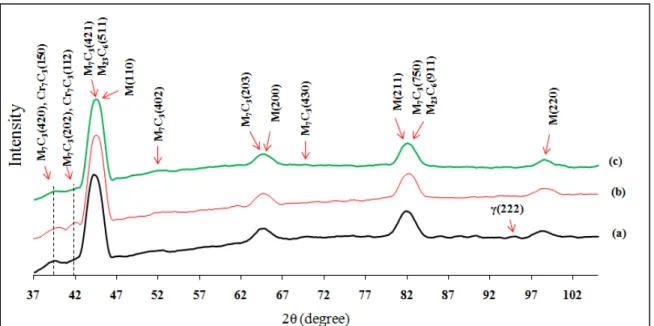
fraction of carbides in comparison with conventional heat treatment using image analysis results from the microstructures of: (a) as-quenched, (b) conventionally heat treated, and (c) cryogenically treated samples. Higher volume fraction of carbides with average diameter below 1µm was obtained after (c) in comparison with (b). ...27 Figure 2-5 X-ray diffraction line profiles of (a) quenched, (b) conventionally
heat treated, and (c) cryogenically treated specimens showing different evolution in carbides types after each treatment. Each profile represents the set of (hkl) indicating different diffraction planes of martensite, M7C3, M23C6, Cr7C3 carbides (existence of
small (222) peak of retained austenite in the quenched sample). Retained austenite peak was eliminated after (b) and (c) treatments in different ways. Enhancement in the volume fraction of Cr7C3
carbides observed after conventional heat treatment (b) was slowed down or even stopped by (c) cryogenic treatment. ...29 Figure 2-6 Simultaneous enhancement in strength and ductility from (a)
conventionally heat treated sample to (b) cryogenically treated samples using true stress-strain(σ-ε) diagrams and related strain hardening behavior (θ-ε diagrams). θ is defined in the figure. In the case of the cryogenically treated samples (b) a fourth stage was revealed in the θ-ε diagram showing negative and almost constant θ (i.e. post-uniform plastic strain) indicating that cryogenic treatment results in concomitant increase of strength and ductility. ...30 Figure 2-7 SEM micrographs from the fracture surface of (a) conventionally
heat treated and (b) cryogenically treated samples after uniaxial tensile tests. Cleavage facets in primary carbides, cracking of primary carbides,
indicated by red dashed lines, and dimples on secondary carbides, numbered from 1 to 3, are present for the two conditions. In (c) an area from sample (b) showing ductile fracture is illustrated. ...31
Figure 2-8 The carbides with average diameters below 1μm are highlighted by red spots in the image using image analyzing software to compare their volume fraction and distribution in (a) conventionally treated sample and (b) cryogenically treated one. Higher volume fractions with more uniform distribution of carbides is shown in (b) which results in higher UTS as indicated in mechanical testing results (Fig.2-6). ...35 Figure 3-1 Influence of cooling rate on the resulted microstructure (a: optical image)
and (b to d: SEM micrographs): cooling rate 0.5K.s-1 (e to f): cooling rate
50K.s-1, observation of carbides (C), allotriomorphic ferrite (ATF),
Widmanstätten ferrite (WF), Acicular ferrite (AF), and Bainite (B) during low cooling rate (a-d) and observation of C and martensite (M) for high cooling rate conditions (e: optical image, f: SEM micrograph). ...44 Figure 3-2 (a) and (b) Bright and dark field TEM micrograph showing bainite plate
consisted of much smaller subunits after cooling at a rate of 0.5K.s-1, (c) and (d): Bright and dark field TEM micrographs from martensitic
microstructure showing mixed laths and plates of martensite after cooling at a rate of 50K.s-1. ...45 Figure 3-3 Dilatometric curve of alloy during cooling at rate of 0.5K.s-1 with
determination of different phase transformation ranges (b) Changes in dilatational strain (black curve) between 400K and 600K from part (a) and its temperature derivative (d (∆L/L0)/dT (green curve) revealing
AF formation region before start of bainitic transformation. (Symbol description: (CP): Carbides precipitation, (ATF):
allotriomorphic ferrite, (WF): Widmanstätten ferrite, (AF): Acicular ferrite, and (B): Bainite ...46 Figure 3-4 (a) Dilatometric curve of alloy during cooling at rate of 50K.s-1
depicting the start of martensitic transformation, (b) Changes in dilatational strain (black curve) between 420K and 580K from part (a) and its temperature derivative (d (∆L/L0)/dT (green curve) to
determine Ms1 (T) and Ms2 (T). (Symbol M denotes martensite) ...46
Figure 3-5 Effect of two applied cooling rates on the volume fraction of carbides with average area below 1µm2 in the microstructure after (a): cooling rate 0.5K.s-1 and (b): cooling rate 50K.s-1. ...47 Figure 4-1 Typical cryogenic treatment of tool steels. ...54 Figure 4-2 CCT diagram for AISI D2 tool steel, cooled from 1300K
(http://www.metalravne.com/steelselector/steels/OCR12VM.html). ...57 Figure 4-3 Different test paths used for cryogenic treatment and tempering:
(tA), cooling rate (CR), cryogenic temperature (TC), holding time at
cryogenic temperature (HtC), heating up rate (HU), and tempering
temperature (TT), No.1 and No.2 show the two different sets of
experiments used in this investigation. ...58 Figure 4-4 Example used for measuring the surface density of carbides with
diameter ≤ 1μm, testing condition: A: 10K.s-1, B: 173K, C: 10s, as cooled without tempering. ...59 Figure 4-5 Hardness measurements of samples after batch No.1 of experiments
as shown in Fig.4-3. ...60 Figure 4-6 (a) Pareto graph for standardized hardness (vertical line showing the
value limit of significance), (b) response graph of factors affecting hardness, and (c) response graph showing the influence of
interactions on hardness evolution(coded variable was used for data analysis). ...61 Figure 4-7 A comparison between measured hardness values and predicted
ones using Eq.4.1. ...63 Figure 4-8 Dilatometry diagrams, heating portion from cryogenic temperature to
tempering temperature : (a) CR: 50K.s-1, T
C:173K, HTC: 10s,
HU: 0.5 and 5 (K.s-1), TT: 500K, (b) CR: 50K.s-1, TC:173K,
HTC: 300s, HU: 0.5 and 5 (K.s-1), TT: 500 K, symbols denoting:
(CR: Cooling rate, TC: Cryogenic temperature, HTC:
Holding time at cryogenic temperature, HU: heating up rate, TT: tempering temperature). ...65
Figure 4-A3 ANOVA analysis for factors indicated in Table 4.1 without considering carbide surface density as influential factor : (a) Pareto graph for standardized hardness (vertical line showing the value limit of significance), (b) response graph of factors affecting
hardness...72 Figure 5-1 (a) Dilatation diagram during cooling at the rate of 10K.s-1 depicting
the start of martensitic transformation(Ms), (b) curve fitting results
based on Eq.5.5 in comparison with experimental results in the region where transformation occurs in part a, (c) change in volume fraction of
martensite versus under cooling calculated by Eq.5.5, (d) evolution of compressive strain during holding time at austenitization temperature. The maximum compression strain was obtained by subtracting the highest expansion value from the value right before the start of cooling (range is shown by red dashed lines). ...80
Figure 5-2 (a) Dilatation diagram during cooling at the rate of 50K.s-1 depicting the start of martensitic transformation(Ms), (b) curve fitting results
based on Eq.5.5 in comparison with experimental results in the region where transformation occurs in part a, (c) change in volume fraction of martensite versus under cooling calculated by Eq.5.5, (d) evolution of compressive strain during holding time at austenitization temperature. The maximum compression strain was obtained by subtracting the highest expansion value from the value right before the start of cooling (range is shown by red dashed lines). ...81 Figure 5-3 (a) SEM micrograph of the alloy cooled at the rate of 10K.s-1, (b) SEM
micrograph of the alloy cooled at the rate of 50K.s-1 (microstructure features: primary large carbides and secondary carbides; no trace of grain boundaries). ...82 Figure 5-4 The effect of higher cooling rate on the suppression of carbide
precipitation during cooling (a) BSE-SEM micrograph from
microstructure of the alloyed cooled at the rate of 10K.s-1 (b) BSE-SEM micrograph from microstructure of the alloyed cooled at the rate of 50K.s-1, (c) diagram showing the number
of carbides with size less than 1μm for conditions in parts (a) and (b), (d) XRD diagrams showing (421) peak of M7C3
carbide and (111) of martensite (overlap is due to very close diffraction angles). ...84 Figure 5-5 Morphology of martensite as result of cooling at the rate of 50K.s-1 (a) bright-field TEM image of partly plate type martensite (b) bright-field TEM image of lath type martensite. ...85 Figure 5-6 (a) Nano-twins (circled area) in the substructure of the alloy cooled at the
rate of 50K.s-1 (b) higher magnification of the same area showing high density of dislocation in smaller bands (≈ 10nm thick) (c) very high magnification showing one nano-twin (yellow circle shows the area over which SAD pattern was taken, (d) corresponding analysis of SAD
pattern. ...86 Figure 5-7 Effect of cooling rate on the resulted b factor from Eq.5.5. ...87 Figure 5-8 Chemical Gibbs free energy changes during diffusionless
transformation from austenite to martensite (ferrite) extracted from Thermo-Calc database TCFE7, given for the
composition of austenite at 1303K. ...89 Figure 6-1 Chemical driving force for FCC to BCC transformation of
by the thermodynamic description in [23] (b) AISI D2 tool steel by ThermoCalc software and TCFE7 database.. ...100 Figure 6-2 (a) Contribution from Zener-ordering and α”-ordering to Gibbs free
energy of BCC for a Fe-0.52wt%C steel, (b) Gibbs free energy changes of FCC to BCT transformation including Zener-ordering and α”-ordering contributions for a Fe-0.52wt%C steel.. ...101 Figure 6-3 Martensite morphology obtained after cooling at the rate of 10K.s-1
(a) bright-field TEM image of mixed plate and lath morphology (b) nano-twins (circled area) in the substructure of the alloy cooled at the rate of 10K.s-1. ...106 Figure 6-4 (a) Lens-shaped particles circled inside the plate of martensite (b)
nano-twins (circled area) in the substructure of the alloy cooled at the rate of 50K.s-1 (c) dark filed TEM micrograph from the same plate of martensite illustrated part a (d) selected area diffraction (SAD) pattern of these particles showing the η-carbides (e) chemical analysis taken over areas numbered 1 and 2, (f) the chemical composition and EDS diagrams showing two types of carbides. ...107 Figure 6-5 Gibbs free energy diagrams of disordered, Zener-ordered, and α″-ordered
in simplified Fe–C alloy at 250K obtained by the thermodynamic description in [23]. X1s and X2s symbols denote the limits of spinodal
decomposition and X1e and X2e representing the boundaries for
LIST OF ABREVIATIONS
A: Austenitizing AF: Acicular Ferrite
ANOVA: ANalysis Of Variance ATF: AlloTriomorphic Ferrite B: Bainite
BCT: Body Centered Tetragonal BSE: Back Scattered Electron C: Cryogenic treatment
CCT: Continuous Cooling Transformation CHT: Conventionally Heat Treated
CP: Carbide Precipitation CR: Cooling Rate
EDS: Energy Dispersive Spectroscopy HRC: Hardness Rockwell C
HtC: Holding time at cryogenic temperature
HU: Heating Up HV: Hardness Vickers
LSC: Large Secondary Carbide M: Martensite
Mf: Martensite finish temperature
Ms: Martensite start temperature
OM: Optical Microscope PC: Primary Carbide
PIPS: Precision Ion Polishing System Q: Quenching
SAD: Selected Area Diffraction SEM: Scanning Electron Microscopy SSC: Small Secondary Carbide T: Tempering
TA: Austenitizing temperature
tA: Holding time at austenitic temperature
TC: Cryogenic Temperature
TEM: Transmission Electron microscope TT: Tempering temperature
UTS: Ultimate Tensile Strength WF: Widmanstätten Ferrite XRD: X-Ray Diffraction
LIST OF SYMBOLS AND UNITS OF MEASUREMENTS ϑ : The average volume of the newly formed martensite plates
γ α
ΔG→ : The chemical driving force of austenite to martensite (ferrite) transformation
∆G: The volume free energy change accompanying transformation b: A material constant varying with chemical composition
d: The shrinkage due to expansion coefficient dT: Temperature variation,
E (BCC-FCC): The strain energy of the transformation of FCC austenite to BCC martensite E: The total dilatation at a i-th temperature
E0: The dilatation at Ms
fm: The volume fraction of martensite
i: i-th experimental point,
K: Kelvin
X1e and X2e: The boundaries for the miscibility gap
X1s and X2s: The limits of spinodal decomposition
xc: Carbon content
ά: Martensite
αm: The expansion coefficient of martensite
αγ: The expansion coefficient of austenite
β: Rate parameter γ: Austenite ε: Strain
ε: Transition carbide
εγ-m: The strain due to lattice volume differences between austenite and martensite
η: Transition carbide
θ: Strain hardening coefficient σ: Stress
σy: Yield strength of austenite
φ: A proportionality constant
INTRODUCTION
Tool steels are known for their very high strength along with high wear resistance (Arai et al. 1991). These properties are due to their specific chemistry and a microstructure obtained through a heat treatment process comprised mainly of hardening (austenitizing and quenching) cycle, and one to three tempering cycles (Roberts et al. 1998). They generally contain 0.3 to 2 (wt%C), and alloying elements such as Mo, Cr, W, and V (Arai et al. 1991, Roberts et al. 1998). The final microstructure of these steels is composed of martensite as matrix, carbides and some undesired retained austenite (Roberts et al. 1998). Generally after quenching from austenitizing temperature, a fully martensitic microstructure is desired; however, compositional effects may push down the martensite transformation start (Ms) and
finish (Mf) temperatures to very low values and stabilize the austenite phase at room
temperature. The presence of non-transformed austenite after heat treatment is detrimental to the performance in service (Roberts et al. 1998). Cryogenic treatment, (holding at between 200K and 77K) as a supplemental step to the conventional heat treatment, has proved to be an efficient way for removing retained austenite (Singh et al. 2011). It has also shown very promising perspectives in achieving significant improvement in mechanical properties and wear resistance of tool steels (Singh et al. 2011).
However, there are controversies among the researchers about the possible root causes for the improved mechanical and wear properties obtained after cryogenic treatment. For example, on the time length for cryogenic treatment suggestions exist from few seconds to several days (Singh et al. 2011). Controversies are due to insufficient understanding on the fundamental mechanisms governing the phase transformation at cryogenic temperatures. A lack of systematic investigations about the operating mechanisms at cryogenic temperature and the influence of cryogenic process parameters on microstructure evolution and properties is evident. The objective of the present PhD research project is to address the above questions and develop a better understanding of the fundamental micromechanisms operating during cryogenic treatment.
This thesis starts with an overview on the conventional cryogenic treatment and its effect on microstructure evolution and enhancement in wear and mechanical properties (Chapter 1). This chapter summarizes different point of views on the root causes for obtaining better mechanical and wear properties in tool steels after cryogenic treatment. Then, the state-of-the-art on cryogenic treatment is described and the challenges are identified.
The first article from this work, published in Journal of Materials Science and Engineering A
(24 March 2014, volume: 598, pp.413-419) is presented in Chapter 2. This chapter describes the results of an experimental study on conventional cryogenic treatment and discusses the possible reasons for strength and ductility enhancement in AISI D2 tool steel. A methodology is proposed to relate the mechanical properties enhancements to the analysis of strain hardening behavior during mechanical testing and carbides coarsening behavior. The objective is to find possible answers for some of the questions raised in Chapter 1 regarding the possible improvement in strength and ductility after cryogenic treatment.
The second article from this work, published in Journal of Materials Science and Engineering A (14 May 2015, volume: 634, pp.32-36) is presented in Chapter 3.This chapter discusses on the influence of starting microstructure on the response of the cryogenic treatment. Using high resolution dilatometry and electron microscopy, it is shown that conventional cryogenic treatment fails to fully transform austenite to martensite. An alternative transformation path is proposed which produces multiphase microstructure with mostly bainite and a few allotriomorphic ferrite, Widmanstätten ferrite, and acicular ferrite instead of martensitic. The proposed approach allows optimizing the cryogenic process for concomitant enhancement in the wear and mechanical properties.
The third article was adopted from Chapter 4 and published in International Journal of Advanced Manufacturing Technology (27 October 2015, online version, pp. 1-10). In this chapter, using design of experiment a series of dilatometry tests are carried out on samples with a fully martensitic structure before cooling to cryogenic temperatures. The influence of cryogenic process parameters on the hardness variation is discussed. Specifically the
influence of (1) cooling rate, (2) cooling temperature, (3) holding time at cryogenic temperature, (4) heating rate, (5) tempering temperature as controllable variables, and (6) surface density of carbides with average diameter below 1 µm as non-controllable variable are investigated.
The fourth article from this work, published in Journal of Materials Science (29 May 2015, volume: 50, pp.5758-5768) is presented in Chapter 5. This chapter discusses the findings on the characteristic of martensite produced by cryogenic treatment. The kinetics of martensitic transformation is investigated to determine the variation in the volume fraction of martensite during cryogenic cooling. For kinetic study, the dilatation data are analyzed using numerical methods and a modified equation is proposed for the determination of transformation rate parameter and the total volume fraction of martensite after cryogenic treatment. Using high resolution transmission electron microscopy, microstructural features are observed and discussed.
The fifth scientific article proposed and submitted from this work is presented in Chapter 6. This chapter focuses on identifying the nucleation sites responsible for the formation of η-carbides after cryogenic treatment. The formation of η-carbides has been reported as the possible root cause for enhanced mechanical and wear properties after cryogenic treatment. A methodology is proposed to calculate the chemical deriving force of martensitic transformation at cryogenic temperatures with considering Zener-ordering contribution where carbon mobility is sufficient. The applicability of the thermodynamic formalism is evaluated for temperatures down to 0K and the possibility of a secondary ordering versus Zener-ordering is investigated. The transformation barriers are determined to be the strain energy required for the activation of martensitic transformation at martensite start temperature and most importantly the cooling rate-dependent strain energy stored in austenite. This chapter discusses also on the mechanism responsible for the formation of η-carbides induced by cryogenic treatment.
Finally a summary covering all the information from Chapters 2 to 6 is presented in Conclusions section to link the outcomes from each chapter and present the original contribution to knowledge toward the principal objective of the thesis.
CHAPTER 1
LITERATURE REVIEW 1.1 Martensite in steels
Martensite is a hard microconstituent found in quenched carbon steels. Transformation of austenite (γ) to martensite (ά) starts at a specific temperature called martensite start temperature (Ms), and it finishes at martensite finish temperature (Mf). The γ to ά reaction
cannot take place until the specimen is cooled to a specific temperature below T0, the
temperature at which the free energy difference (ΔG γ to ά) between fcc-austenite (Gγ) and bct-martensite (Gά) of the same composition is zero (Fig. 1-1(a)) (Nishiyama 1987). The greater is the degree of supercooling; the larger will be the difference between the two crystal structures, because it is more difficult for the change to occur when the structures are very different. In the case of steel, the difference between the two structures is rather large and the difference between T0 and Ms may be as large as 200K (Nishiyama 1987).
In carbon steels, the carbon atoms remain at octahedral sites during martensitic transformation and generate elastic strains around them. The elastic strains lead to the formation of tetragonal (bct) structure instead of bcc structure (Krauss 1999 and Bhadeshia 2002). This tetragonality strengthens the matrix and increases the hardness of steel. It can be said that the formation of martensite is carbon steels is one of the strengthening mechanisms of the matrix (Krauss 1999). Martensite, depending on the carbon content, can have either lath or plate or mixed morphology. The formation of twinned martensite is also possible (Krauss 1999). The martensite start and finish temperatures decrease by adding more carbon to steel. Figure 1-1(b) summarizes the relation between carbon content, Ms temperature, and
resulted morphology in Fe-C alloys (Krauss 1999).
Martensite is produced through a diffusionless process. The evidences supporting this character are: (a) possibility of formation at very low temperatures (b) very high growth rate close to 1100 ms-1, which is much higher than the fastest recorded velocity for solidification
front, and (c) the chemical composition of ά is shown to be identical to that of the parent γ (Bhadeshia 2002).
(a)
(b)
Figure 1-1(a) Free energy changes between γ and ά, (b) Martensite start (Ms) temperatures and martensite
morphology as a function of carbon content in Fe-C alloys (Marder and Krauss 1967, Krauss 1991, Wilson 1994).
The tetragonality observed during martensitic transformation is not only the effect of diffusionless transformation and the interactions between Fe and C atoms may generate ordering in the martensite crystal structure (Zener 1946). The Zener ordering keeps the carbon atoms in this c-sublattice and prevents their migration to octahedral sites in other
sublattices only within the temperature range where carbon atoms are sufficiently mobile for such migration (Zener 1946). For steels such as AISI D2 with 0.52wt.% carbon in the martensite, the complete ordering is estimated to occur at temperatures close to 150K based on thermodynamic approach but the carbon mobility is also essential and should be taken into account. Therefore, the martensitic transformation doesn’t complete by cooling to room temperature and it would be continued until cryogenic temperatures where carbon mobility is feasible (T>223K) (Tyshchenko et al. 2010). It has been reported that martensitic transformation has an athermal nature i.e. independent of time. Koistinen and Marburger (Bhadeshia 2002, Bhadeshia 2013) proposed an empirical equation (Equation 1-1) to study the kinetics of martensitic transformation and quantified the extent of transformation as a function of the degree of undercooling.
1-Vα′ =exp[ (β M Ts- )] (1-1) where β is - 0.011.
For example, in AISI D2 tool steel by considering Ms = 403K (Gavriljuk et al. 2013),
quenching a sample to 173K and 123K gives 92 % and 95 % volume fraction of martensite, respectively. Hence, it can be said that at very low temperatures almost complete transformation of γ to ά is possible. Martensite and martensitic transformation are playing an important role in improving the mechanical properties of AISI D2 tool steel. Hence, a good understanding of martensite characteristics, the thermodynamics and kinetics of its transformation for investigated alloy will be very beneficial in order to optimize the strength, toughness, and wear characteristics of high strength steel where these properties are concomitantly required.
1.2 Introduction to tool steels
Tool steels are used for cutting, forming, or shaping a material into a part or component adjusted to a specified application (Arai et al. 1991). Cutting tool steels show high strength and wear resistance but they should have also good toughness to absorb high energies applied during service (Arai et al. 1991). In addition to cutting tools, many tool steels are also widely
used for machinery components and structural applications such as high-punches and dies, wear-resistant liners, etc (Arai et al. 1991). These alloys contain relatively large amounts of tungsten, molybdenum, vanadium, and chromium. These elements make it possible to meet increasingly rather high service demands and to provide greater dimensional control and freedom from cracking during heat treating. The chart in Table 1.1 contains some of the commonly used tool steels and their alloy content (wt. %) (Tarkany 2000).
Table 1.1 Commonly used tool steels (Tarkany 2000). Steel type C Mn Si Cr W Mo V A2 1.0 0.9 0.3 5.25 0 1.15 0.3 D2 1.5 0.5 0.3 12.0 0 0.9 0.9 M2 0.85 0.3 0.3 4.15 6.4 5.0 1.9 M4 1.4 0.3 0.3 4.0 5.75 4.5 4.0 CPM 10V 2.45 0.5 0.9 5.25 0 1.3 9.75
Each grade of tool steel requires a specific heat treatment procedure in order to achieve the optimum properties for any given application (Weast 1981-1982, Arai et al. 1991, Tarkany 2000). The final microstructure of these steels is composed of martensite (matrix), carbides and some undesired retained austenite. In this project, the focus will be on the heat treatment cycle of AISI D2 tool steel.
1.3 General production cycle for a tool steel
The production cycle of a tool steel consists of ingot casting, thermomechanical (hot forging and/or rolling), machining, and thermal heat treatments (Arai et al. 1991, Roberts et al. 1998). The thermomechanical treatment starts after casting and it consists of hot forging or rolling in order to homogenize the cast microstructure and break down the large networks of eutectic carbides formed during casting (Arai et al. 1991, Roberts et al. 1998). After that, annealing stage is carried out to generate uniform microstructure. Most of the tool steels are formed or machined to produce the desired shape prior to hardening heat treatment (Arai et al. 1991, Roberts et al. 1998). Figure 1-2 (a) shows the typical initial thermomechanical
treatment and (b) conventional heat-treatment sequences including hardening (austenitization and quenching) and tempering as a function of time, temperature, and phase transformation (Arai et al. 1991, Roberts et al. 1998).
.
Figure 1-2 Plots of temperature versus time showing sequence of operations required to produce tool steels. (a) thermomechanical processing. (b) hardening heat treatment. L, liquid; A, austenite; C, cementite; F, ferrite; Ms
temperature at which martensite starts to form on cooling; RT, room temperature (Arai et al. 1991).
During quenching, martensitic transformation progresses until temperature falls to Mf. The
Mf temperature can be below room temperature, so austenite might only, to some extent,
transform to martensite with the remaining structure being retained austenite and undissolved eutectic carbides. The carbon content and additive alloying elements affect both Ms and Mf
temperatures (Fig.1-3). Some alloying elements increase Ms and Mf while others reduce
them. In AISI D2 tool steel, carbon and chromium (main alloying elements) reduce both Ms
and Mf temperatures (Fig.1-3). For AISI D2 tool steel Ms and Mf were measured as 403K and
173K, respectively (Gavriljuk et al. 2013). Martensitic microstructure after the hardening cycle (austenitizing and quenching) is hard and brittle (Speich and Leslie 1972). Tempering is the process of heating martensitic steels to temperatures close to 773K so that they become more ductile (Speich and Leslie 1972). Tempering involves the segregation of carbon to lattice defects, and the precipitation of carbides, and the decomposition of retained austenite. Based on the temperature range selection for tempering, different stages are proposed for microstructure evolution in tool steels (Speich and Leslie 1972).
Figure 1-3(a) Effect of carbon content on Ms and Mf temperatures, (b)
effect of alloy content on Ms temperature (Weast 1981-1982).
The first stage consists of heating to temperatures between 373K and 473K, which is the region for the formation of transitional carbides such as epsilon (ε) (hcp crystal structure) and eta-carbides (η) (orthorhombic crystal structure). The second stage is called decomposition of retained austenite and it occurs in the range of 473K to 573K. Cementite (Fe3C,
orthorhombic) forms when most steels are tempered between 523K and 973K. This step is called the third stage of tempering. If, carbide-forming alloying elements such as Ti, Mo, V, or W are added to the steel, a further and important strengthening reaction will occur between 773K and 873K. This stage will be the fourth stage of tempering and it is also called secondary hardening stage (Speich and Leslie 1972).
Studies on the evolution of mechanical properties of AISI D2 tool steel has shown good combination of high hardness and high wear resistance after conventional heat treatment (Roberts et al. 1998) but also researches have also reported poor ductility of the alloy after conventional heat treatment (Teymuri et al. 2011). The decomposition of austenite to ferrite, the formation of film like cementite, and the segregation of embrittling elements such as Cr at prior austenite grain boundaries during tempering are proposed as root causes for the observed poor ductility (Speich and Leslie 1972, Ghasemi-Nanesa and Jahazi 2014). In order to transform all the austenite to martensite before tempering, the Mf temperature should be
1.4 Cryogenic treatment of tool steels
Cryogenic treatment was initially introduced as an additional step to the heat treatment cycle of tool steels to remove the retained austenite. It showed significant improvement in service wear life and hardness of tool steels (Miller 1980). Originally, it consisted of the following steps: (1) Austenitizing (A); (2) Quenching (Q); (3) Tempering (T); (4) Cryogenic treatment (C) (Tarkany 2000). Kelkar et al. (2007) have studied different combinations of the above steps: (a) A+Q, (b) A+Q+T, (c) A+Q+T+C, (d) A+Q+C, and (e) A+Q+C+T.
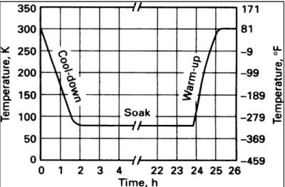
They concluded that A+Q+C+T combination shows higher toughness in addition to the increase in hardness. A typical cryogenic treatment consists of cooling down from ambient temperature to the temperature of liquid nitrogen. When the material reaches approximately 77K, it is soaked for an appropriate time before being removed from liquid nitrogen and allowed to warm up to the ambient temperature (Fig.1-4) (Singh et al. 2011).
Figure 1-4 Plot of temperature versus time for the cryogenic treatment (Singh et al. 2011).
Two distinct approaches have been used for cooling and heating rates: 1) Cool or reheat the material as fast as possible to or from the cryogenic temperature, and 2) Apply a gradual (slow) cool down and reheating. In the latter case, several hours are required to complete this step (Reitz and Pendray 2001).
Direct immersion of components in liquid nitrogen bath and the resultant abrupt cooling to very low temperatures may lead to the development of excessive thermal stresses (and also structural stresses (Reed-Hill and Abbaschian 1992) which may induce cracking of the components. Kamody (1999) reported that cooling rate has little effect on the properties of final products and so it should be carried out as rapid as possible to minimize the treatment time. The same approach has been suggested by Kamody for the reheating rate from cryogenic temperature to room temperature. However, it is well recognized that cracking can occur by rapid cooling (Reitz and Pendray 2001). So, slow cooling and even slower heating rate is required in order to avoid crack initiation. Molinari et al. (2001) suggested that in order to avoid cracking of the component, cooling rate must not exceed 0.3 to 0.5 (K.min-1). Commonly proposed cooling rates are 0.3 to 1.2 (K.min-1). Lal et al. (1996, 2001) have used a cooling rate of 1.15 K.min-1 and heating rate of 0.56K.min-1 for AISI M2, D3 and T1 steels. However, some investigators have opted slow but identical rate for both cooling and heating, such as 1.0K.min-1 for AISI M2 steel by Silva et al. (2006). For AISI D2 steel, Wang (2006) has reported that the faster the cooling rate is, the higher would be the level of improvement in hardness and wear resistance.
Another parameter in cryogenic treatment is the soaking time at cryogenic temperature. Kamody states that soaking time is unrelated to the final mechanical properties. According to his patent (Kamody 1993), the main objective is to transform retained austenite to martensite. This transformation is dependent only on the cryogenic temperature and not on the time held at that temperature. A soaking time of 10min is suggested to allow the material to achieve thermal equilibrium before it is removed and reheated. If the final properties of the material are independent of the time at cryogenic temperature, this time should be minimized to reduce the treatment cost. Reports have indicated that for H13 and D2 tool steels, there is
little or nothing gained by long soaking times (Barron 1983, Moore and Collins 1993, Reitz and Pendray 2001).
By contrast, Dobbins and Barron state that, the time the material is allowed to stay in the cryogenic condition impacts the final properties (Dobbins 1995, Collins 1996). This soaking time is required for the atoms in the material to diffuse to new locations; a time of the order of 20hrs is suggested (Barron 1983, Dobbins 1995). Moore and Collins (1993) reported the effect of soaking time on hardness of three different steel samples. They indicated that Vanadis 4 (a chromium-molybdenum-vanadium alloyed steel) and D2 tool steels were unaffected by the duration of cryogenic while H13 tool steel, showed a higher hardness after soaking for 400min. An optimum soaking time may therefore exist for each type of material as illustrated in Fig.1-5 for H13 steel (Reitz and Pendray 2001). Collins (1996, 1998) and Collins and Dormer (1997) showed that soaking time affects the hardness, wear resistance, and carbide density of a variety of steels. Additional time is important for any transformation/precipitation to be completed at such low temperatures because diffusion is very slow. On the contrary, work by Barron (1983) has shown that plain carbon steels and cast irons are not affected by soaking time during cryotreatment.
Figure 1-5 Changes in hardness of H13 tool steel with soaking time (Reitz and Pendray 2001)
From the processing point of view, the cooling and heating rates should be fast enough to achieve better performance of tool/die steel components by cryogenic treatment and to reduce the process cost; however, these rates should be slow enough to avoid development of
microcracks in the component. With the present state of knowledge, systematic studies are required to find the effect of cooling and heating rates and soaking time on microstructure evolution and mechanical properties.
1.5 Metallurgy of cryogenically treated tool steels
Available data in the literature relevant to the structure-property relations of tool steels subjected to cryogenic treatment are not coherent and the fundamental proposed reasons for achieving improved mechanical properties like wear resistance are not well documented. The proposed mechanism for the superior wear resistance of tool steels after cryogenic treatment can be generally classified in three categories:
1) Transformation of retained austenite to martensite (Barron 1983, Moore and Collins 1993, Dymchenko and Safronova 1993, Cohen and Kamody 1998, Blankinship 2001, Babu et al. 2005, Yang et al. 2006, Zhirafar et al. 2007),
2) Precipitation of refined carbide particles (Paulin 1993, Meng et al. 1994, Yugandhar et al. 2002, Zurecki 2005, Stratton 2007, Dhokey and Nirbhavne 2009), and
3) Combined effect from transformation of retained austenite to martensite and precipitation of fine carbide within martensite (Collins 1996, Collins and Dormer 1997, Yun et al. 1998, Mohan et al. 2001, Preciado 2006). Each of the above categories will be discussed in the following sections.
1.5.1 Transformation of retained austenite to martensite
As mentioned in section 1.3, austenite in tool steel transforms to martensite, undissolved eutectic carbides, and retained austenite. Thus, cooling to cryogenic temperatures (T<Mf)
promotes the transformation of retained austenite to martensite and increases the hardness of steel. Gulyaev (1937) was the first who studied cryogenic treatment of tool steels and reported enhanced wear resistance. The transformation of retained austenite to martensite with a more stable structure was proposed as the root cause for the improvement brought by cryogenic treatment. The results obtained by Gulyaev were later confirmed by many other
researchers (Barron 1983, Moore and Collins 1993, Dymchenko and Safronova 1993, Cohen and Kamody 1998, Blankinship 2001, Babu et al. 2005, Yang et al. 2006, Zhirafar et al. 2007).
Barron (1983) used two different cryogenic temperatures, 198K and 77K, and concluded that treatment at 77K (deep process) was more productive in that more transformation of retained austenite to martensite took place. He also proposed that room temperature ageing of austenite should be avoided because it stabilizes the austenite and even the cryogenic treatment could not transform austenite to martensite. Finally, he proposed that in presence of retained austenite, wear behavior will not be improved. Zhirafar et al. (2007), using neutron diffraction technique, showed that the most important microstructural result of cryogenic treatment of AISI 4340 steel was a small reduction in the quantity of retained austenite, which was transformed to martensite (Fig.1-6). From the above discussion, it can be concluded that the conversion of retained austenite to martensite, and the related increase in hardness due to the higher amount of martensite, is considered by many researchers as the reason for enhanced wear resistance of tool steels. The analysis of published literature also indicates that in order to maximize the cryogenic effect, austenite stabilization must be avoided. To this end, the cryogenic treatment should be carried out immediately after quenching and γ-stabilizer alloying elements should be added more carefully to avoid austenite stabilization.
Figure 1-6 The neutron diffraction profile for (a) austenite at 1118K, oil-quenched, and (b) austenitized at 1118K, oil- quenched, and
cryogenically treated (Zhirafar et al. 2007).
1.5.2 Precipitation of refined carbide particles
Another group of researchers have reported that cryogenic treatment, in addition to the transformation of retained austenite to martensite, brings metallurgical changes within the martensite which improves mechanical properties (Paulin 1993, Meng et al. 1994, Yugandhar et al. 2002, Zurecki 2005, Stratton 2007, Dhokey and Nirbhavne 2009). They attributed the improvement in the mechanical properties to inter-martensite alterations rather than to
austenite–martensite transformations (Paulin 1993, Meng et al. 1994, Yugandhar et al. 2002, Zurecki 2005, Stratton 2007, Dhokey and Nirbhavne 2009). Meng et al. (1994) studied the wear behavior of Fe-12wt%Cr-1 wt%Mo-1 wt%V-1.4 wt%C tool steel and related it to the formation of fine carbides (η-carbides) within martensite after cryogenic treatments and low temperature tempering cycle.
These carbides are different in size and shape from the primary carbides which are formed during the tempering process. These authors also reported changes in the lattice parameter of martensite after cryogenic treatment and indicated that these changes contribute more to enhance the strength and toughness of the material rather than the transformation of retained austenite to martensite (Meng et al. 1994). Yugandhar et al. (2002) found that precipitation of η-carbides occurs only during the tempering process after deep cryogenic treatment which is a different result from the ones reported by Meng (1994). Zurecki (2005) studied the effects of various quenching media including liquid nitrogen (77K) and liquid helium (4K) on microstructure and selected properties of A2 grade tool steel. The author reported the presence of a large number of finely dispersed dark carbides, with a typical size of 100-250nm in cryogenically treated samples as shown in Fig.1-7 (Zurecki, 2005). Stratton (2007) reported that time dependent decomposition of primary martensite at cryogenic temperature is related to nucleation of numerous coherent nano carbides (η-carbides) which bring wear resistance enhancement. This finding is in agreement with the work reported by Meng et al. (1994). In a recent study, Dhokey and Nirbhavne (2009) employed AISI D3 steel, with multiple tempering after cryogenic treatment, and showed that multiple tempering coarsens the carbides formed during cryogenic treatment resulting in reduced wear resistance of the final product.
Figure 1-7 Scanning electron microscopy (SEM) image of A2 sample: (a) oil-quenched and tempered; (b) cryogenically treated in liquid nitrogen for 24 hrs
(Dhokey and Nirbhavne 2009).
1.5.3 Combined effect from retained austenite transformation to martensite and fine carbide precipitation within martensite
The third group of researchers reported that the transformation of retained austenite into martensite and the modification of martensite and precipitation of a different type of carbides are playing important roles in wear resistance improvements of tool steels (Collins 1996, Collins and Dormer 1997, Yun et al. 1998, Mohan et al. 2001, Preciado 2006).
Collins (1996) studied the influence of cryogenic treatment on the enhancement of properties such as hardness, toughness, wear resistance, dimensional stability, corrosion resistance of cold work (D2) and high-speed (ASP 23) steels. He observed hardness enhancement, increase in dimensional stability, toughness reduction, and a small increase in wear resistance. These findings were related to the full transformation of austenite to martensite. He also found that holding at cryogenic temperature for sufficient time would produce a large number of fine carbides during subsequent tempering which will improve wear resistance and toughness. Collins and Dormer (1997) examined the effect of cryogenic treatment on hardness, toughness, wear resistance, and microstructure of D2 tool steel. Results showed the presence of retained austenite after cryogenic treatment and little variation in size and
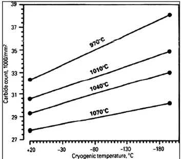
distribution of carbides (Collins and Dormer 1997). The effect of cryogenic temperature on carbide count (carbides finer than 5nm) is shown in Fig.1-8 (Collins and Dormer 1997). It can be seen that by reducing temperature to cryogenic range for a constant austenitizing temperature, the number of counted carbides increases. However, by increasing austenitization temperature, the number of carbides was reduced (Collins and Dormer 1997).
Figure 1-8 Effect of cryogenic temperature on carbide counts in D2 tool steel, after austenitizing
at various temperatures (Collins and Dormer 1997).
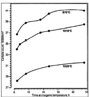
The effect of holding time at cryogenic temperature on the count of carbides is shown in Fig.1-9. For a constant austenitizing temperature, longer soaking time at cryogenic temperature increases the number of carbides but their rate of formation is reduced. In addition, higher austenitizing temperature shows lower count for carbides because of their dissolutions at higher temperatures. Based on Collins and Dormer study (1997), the complete transformation of retained austenite to martensite does not happen after cryogenic treatment and instead new carbides are formed. However, in their work the governing mechanisms and the required driving force for the formation of the new type of carbides were not discussed.
Figure 1-9 Effect of holding time at 77K on carbide counts in D2 tool steel, after austenitizing at various temperatures (Collins and Dormer 1997).
1.6 Cryogenic treatment: state-of-the-art today
The above literature review showed that the benefits of cryogenic treatment are well recognized by the scientific community and the question on the possible benefits of cryogenic treatment has changed to how this process works. In the present literature review, the ideas for these improvements proposed by different researchers have reviewed; but it is very difficult to draw a cohesive picture. One of the main reasons is the lack of systematic studies covering the entire cycle of the cryogenic process. Specifically, many researchers do not give the complete cycle of their procedure and processing routes. Also, heat treatment cycles, sample size, equipment type, etc are different from one paper to another, thereby making difficult any in-depth analysis. In this thesis, through a systematic design of experiments, the most critical cryogenic process parameters are analyzed and it is attempted to develop a better understanding of the fundamental mechanisms governing cryogenic treatment.
CHAPTER 2
ARTICLE 1: SIMULTANEOUS ENHANCEMENT OF STRENGTH AND DUCTILITY IN CRYOGENICALLY TREATED AISI D2 TOOL STEEL
Hadi Ghasemi-Nanesa, Mohammad Jahazi,
Department of Mechanical Engineering, École de Technologie Supérieure, 1100 rue Notre-Dame Ouest, Montréal (QC) H3C 1K3 Canada.
An article adopted from this chapter has been published in Journal of Materials Science and Engineering A, vol. 598 (2014), pp. 413-419. DOI:10.1016/j.msea.2014.01.065
Abstract
In this research, the effect of cryogenic treatment on microstructural evolution and mechanical properties enhancement of AISI D2 tool steel was investigated. Cryogenic treatment down to liquid nitrogen temperature (77K) was added to the conventional heat treatment between hardening and tempering steps. Electron microscopy investigation showed higher volume fraction of fine carbides with average diameter below 1µm indicating effective retardation in carbide coarsening process as a results of cryogenic treatment. A modification in types of carbides was also observed after cryogenic treatment. X-ray diffraction diagrams revealed transformation of retained austenite to martensite at cryogenic temperature. Weakening or removal of carbides peak in the X-ray diagram was considered as evidence of carbides different behavior at cryogenic temperature.Mechanical testing results indicated higher ultimate tensile strength, better ductility, and higher elastic modulus after cryogenic treatment. Analysis of stress-strain diagrams revealed different strain hardening behavior for cryogenically treated alloy when compared to the conventionally heat treated one. Fractography results confirmed strain hardening behavior and showed cleavage fracture for conventionally treated alloy but mixed cleavage - ductile fracture mode for cryogenically treated alloy. The improved mechanical properties after cryogenic treatment are interpreted in terms of the influence of higher volume fraction and uniform distribution of fine carbides in reducing the average active dislocations length and enhancement of the flow stress at any given plastic strain.
2.1 Introduction
Tool steels are extensively used in modern industry for applications where high strength along with wear resistance and toughness are required [1]. These alloys are characterized by relatively large amounts of alloying elements such as tungsten, molybdenum, vanadium, and chromium and obtain their superior mechanical properties through heat treatment processes specific to each alloy [1-3]. The conventional heat treatment of tool steels consists of solutionizing in the austenitic region followed by quenching and simple or double tempering. The final microstructure of these steels is composed of martensite matrix, primary carbides, and secondary carbides (formed during the tempering step) and some undesired retained austenite [4, 5].
Cryogenic treatment is an additional process to the conventional heat treatment of tool steels originally intended to transform the residual austenite in the microstructure and therefore improve the wear resistance. The process involves cooling the materials down to liquid nitrogen temperature (77K), holding for specific time, and then heating up to room temperature (RT) followed by final tempering [4]. A number of cold work tool steels, high-speed tool steels, carburized steels, and stainless steels have been submitted to cryogenic treatments and the reports show considerable enhancement in wear resistance of these steels [6-10]. Despite the reported results on beneficial effects of cryogenic treatment, investigations about the fundamental mechanism governing cryogenic treatment and their effect on the microstructure of tool steels started only in late 1990’s [6, 11-15].
Transformation of retained austenite to martensite, precipitation of fine η-carbides and relaxation of residual stresses reliefs have been suggested by researchers as possible mechanism responsible for the observed enhancement of wear resistance after cryogenic treatment [6]. However, these studies which mostly started in late 1990’s are limited and have been carried out on different alloys and/or for different heat treatment conditions [6]. Moreover, in recent years in addition to superior wear resistance properties simultaneous high levels strength and ductility are also required, thereby further increasing the interest for
a better understanding of the fundamental mechanisms governing the evolution of the microstructure during cryogenic treatment and its influence on the mechanical properties of tool steels [16-19].
AISI D2 tool steel is cold work tool steel with high strength and good wear resistance after conventional heat treatment but it suffers from poor ductility and brittle fracture. However, in most applications of AISI D2, high strength and good ductility are simultaneously required [7-10]. Although some authors have reported wear resistance enhancement of D2 steels after cryogenic treatment [7-10], others have reported hardness improvement but toughness reduction after cryogenic treatment [20]. More work is therefore required to better understand the interrelationships between cryogenic process parameters, microstructure evolution, and mechanical properties. The present work inscribes in this context and aims to study such interactions after cryogenic treatment of AISI D2 cutting tool steel with the view to find optimum combination of the tensile properties and ductility. In this regard, microstructure evolution and mechanical properties of conventionally and cryogenically treated specimens have been studied using advanced characterization methods and the obtained results analyzed in the framework of existing theories on dislocation interaction with carbon atoms and precipitates.
2.2 Experimental procedure
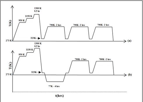
AISI D2 sheets with following chemical composition of Fe-1.54wt%C-0.33wt%Si-0.32wt%Mn-11.88wt%Cr-0.76 wt%Mo-0.75 wt%V-0.008 wt%P-0.008wt%S were employed in this research. Samples were taken in random selection from a large industrial heat treatment batch. The heat treatment process was carried out in an industrial vacuum furnace, consisting of the following: 1) two preheating steps at 950K and 1150K, respectively; followed by temperature rise to 1300K, 2) austenitization at 1300K for 20 minutes followed by Argon quenching with a pressure of 2 bars at about 323K to avoid quench - cracking. For conventional heat treated alloy, three tempering cycles were conducted at 790K-2hrs for each cycle. For cryogenic treatment, the plates were cooled down to 77K with a processing time of
4hrs between quenching and tempering. After cryogenic treatment, two tempering cycles were applied at 790K and 780K, each with duration of 2hrs. The schematics of heat treatment cycles for conventionally (a) and cryogenically (b) treated samples are shown in Fig.2-1.
Figure 2-1 Schematic representing typical time-temperature profile of the applied heat treatment cycles: (a) conventional heat treatment:
austenitizing, quenching, and triple tempering (b) cryotreatment: austenitization, quenching, cryogenic cycle, and double tempering.
For macrohardness measurement, Rockwell(C) hardness tester with major load of 150kg was used. Sub-size samples for tensile tests were prepared according to ASTM-E8 standard. Uniaxial tensile tests were carried out using MTS793 machine with a crosshead speed of 1mm.min-1 using extensometer in order to precisely measure mechanical properties including the ultimate tensile strength (UTS), the ultimate tensile strain, and the elastic modulus. To accurately examine the presence of phases, X-ray diffraction (XRD) analyses were conducted on as-quenched, conventionally treated, and cryogenically treated samples. Angular ranges of 35-105 2θ with Cu-Kα radiation at 45kV and 40mA and a step scanning at 0.022θ with count time of 1second per point were used for the XRD experiments. 3%Nital solution was utilized for etching. Fractographical and microstructural investigations of both
conventionally and cryogenically treated samples were conducted using S3600N (Hitachi) conventional scanning electron microscope (SEM) and field emission SEM- SU70 (Hitachi). The volume fraction of carbides and other second phase particles were calculated using the MIP® image analysis software (Nahamin Pardazan Asia, www.metsofts.com).
2.3 Results
2.3.1 Microstructure characteristics
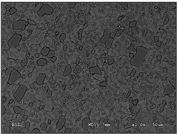
The initial microstructure before hardening treatment is usually the annealed condition (as-received alloy). In the annealed condition, the matrix is composed of ferrite and globular carbides as shown in Fig.2-2. The larger carbides are mostly primary M7C3 carbides formed
on the austenite grain boundaries and then dispersed as a result of hot working [21]. The other carbides such as M2C and M23C6 are the result of secondary precipitation in the
spherodiziation of carbides produced by the transformation of austenite on cooling after normalizing heat treatments. The formation of MC, M2C (same chemical composition to
M7C3 carbides), and M23C6 carbides are possible based on thermodynamic calculations [21].
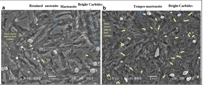
Figure 2-3 shows SEM images from the microstructure of both conventionally and cryogenically treated specimens. The microstructure is composed of tempered martensite, primary carbides (PCs), large secondary carbides (LSCs), and small secondary carbides (SSCs). Comparison between microstructures obtained after cryogenic treatment and conventional treatment indicates that a higher volume fraction of SSCs is present in the microstructure after cryogenic treatment.
Figure 2-2 SEM micrograph of the starting microstructure of the AISI D2 tool steel (annealed
condition). Matrix is composed of ferrite and globular carbides. Larger carbides are mostly primary M7C3 carbides. Small carbides are either
M2C or M23C6.
(a) (b) Figure 2-3 Effect of two applied heat treatment cycles on the presence of
carbides with average diameter below 1µm, in the microstructure of: (a) conventionally heat treated specimen and (b): cryotreated specimen. The microstructures revealed by etching with 3%Nital solution exhibit tempered martensite, primary carbide (PC), large secondary carbide (LSC), and small secondary carbide (SSC). Higher population of SCCs is clearly visible after (b).
Further information about the size and volume fraction of secondary carbides was obtained from image analysis of the unetched microstructure. In fact, etching could cause higher