Abstract — In recent years, Hydro-Québec has undertaken a
major program to upgrade the reliability of its transmission system. Much effort has been focused on increasing the system's ability to withstand extreme contingencies, usually caused by multiple incidents or the successive tripping of transmission lines. This paper deals with the conception and the control logic of an undervoltage load shedding scheme aimed at protecting the Hydro-Québec system against long-term voltage instability. Various results showing the impact of the operation of these automatisms on the system stability are provided in this paper.
Index Terms—Extreme contingency, system protection
scheme, defense plan, long-term voltage instability, load shedding.
I. INTRODUCTION
n order to increase the reliability of its transmission system, Hydro-Québec (H-Q) has developed, over the recent years, an extensive defence plan against major disturbances. In addition to traditional under-frequency load-shedding measures, an extensive generation rejection and remote load shedding scheme – named RPTC [8] – has been installed to handle transient angular stability problems. The final step of this deployment is the undervoltage load shedding scheme – named TDST.
There are two lines of defense against incidents likely to trigger system instability:
• preventive: estimate security margins with respect to credible contingencies, i.e. incidents with a relatively high probability of occurrence. Preventive security criteria state that the system should respond in an acceptable way to (N-1)-type incidents, without the help of automatic post-contingency actions affecting generators and/or loads and with the ability to return to the N-1 secure state as soon as possible (for instance within 30 minutes) ;
Daniel Lefebvre, ing. and Serge Bernard, ing. are with the TransEnergie division of Hydro-Québec, Complexes Desjardins, Tour de l’Est, CP 10 000 Montréal (QC), Canada. E-mails: Lefebvre.Daniel.4@hydro.qc.ca and
Bernard.Serge.2@hydro.qc.ca
Thierry Van Cutsem is a research director of the Belgian National Fund for Scientific Research (FNRS), and adjunct professor at the Dept. of Electrical Engineering and Computer Science (Montefiore Institute) of the University of Liège, Sart Tilman B37, B-4000 Liège, Belgium. E-mail: t.vancutsem@ulg.ac.be.
• corrective: implement System Protection Schemes (SPS) (also referred to as Special Protection Schemes), to face the more severe, but less likely incidents. The latter are typically N-2 or more dangerous disturbances.
This paper focuses on the corrective control of long-term voltage instability, driven by load tap changers, generator overexcitation limiters, switched shunt compensation, restorative loads, and possibly secondary voltage control [1], [2]. This type of instability has become a major threat in many systems.
While load shedding should be used as a last resort, it is an effective countermeasure against voltage instability [3], especially when the system undergoes a severe initial voltage drop that cannot be tolerated for a long time.
As for any SPS, the design of a load-shedding scheme is a challenging task in terms of the number of possible protection settings and the many (pre- and post-disturbance) scenarios necessary to consider.
With its long transmission corridors between the hydro generation areas in the North and the main load centers in the South of the province (see Fig. 1), the H-Q system is exposed to angle, frequency and voltage stability problems.
In addition to static var compensators and synchronous condensers, the automatic shunt reactor switching devices – named MAIS – play an important role in voltage control [7]. These devices, in operation since early 1997, are now available in twenty-two 735-kV substations and control a large part of the total 25 500 Mvar shunt compensation. Each MAIS device relies on a high precision, local voltage measurement while coordination between substations is performed through switching-delay settings. While fast-acting MAIS can improve transient angle stability, slower-acting MAIS significantly contribute to voltage stability.
While RPTC is an event-based SPS (due to the speed of angle instability phenomena), TDST will be response-based (owing to the nature of long-term voltage instability), relying on substation voltages measured in the Montreal area. More precisely, voltages will be measured in five 735 kV substations equipped with MAIS high precision voltage transformer and validated through the data acquisition chains of the TDST acquisition algorithm.
TDST will operate in a pre-defined shedding "load basin" with its control restricted to a certain percentage of the load.
Undervoltage load shedding scheme
for the Hydro-Québec system
D. Lefebvre, S. Bernard, and T. Van Cutsem, Senior Member, IEEE
The set of distribution circuit breakers that can be opened is predefined by the remote load shedding controller also used by RPTC.
II. DESCRIPTION OF TDST
A. Input signal
The TDST system protection system has been designed to operate during extreme contingencies involving the outage of two or more 735 kV lines tripped in the Montreal area (see Fig. 1) which can invoke long-term voltage stability problems. Line trippings are detected using undervoltage measurements.
Abitibi Nemiscau Radisson LG-2 LG-3 LG-4 Lemoyne Albanel Chibougamau Saguenay Churchill Falls Montagnais Arnaud Micoua Chamouchouane Périgny Manicouagan Bergeronne La Vérendrye Chénier Grand-Brûlé Duvernay J-Cartier Laurentides Nicolet Lévis Appalaches Carignan Boucherville Des Cantons Montérégie Hertel Châteauguay 70 42 703 8 70 46 703 6 700 6 70 49 704 8 7 04 4 701 6 704 5 7 047 701 7 70 09 7 094 7 09 3 70 92 7 08 2 70 81 708 0 70 90 707 8 70 77 70 76 708 5 708 4 7 086 70 79 706 1 7 059 706 2 7 063 705 7 70 60 7 070 7 069 70 88 7 089 705 4 7 056 705 5 7 053 7 052 7 051 7 031 70 32 70 33 7 027 7 02 9 7 028 7 019 7 026 7 011 70 04 70 18 7 008 7 02 3 700 7 7 010 70 25 7 024 70 02 70 14 703 4 70 05 70 35 70 97 7 09 5 70 96 NEPOOL
Fig. 1: Hydro-Québec network with highlighted detection zones of TDST.
TDST calculates an average voltage from measurements taken in five 735 kV substations in the Montreal area. The latter are shown in dark in Fig. 1 while Fig. 2 sketches the overall structure of the protection. The measurement sampling rate will be 0.1 second. This average voltage value, denoted V in the sequel, is used provided that three valid measurements out of the five have been received. The protection relies on the mean value not only to allow bad data rejection but also to better identify dangerous disturbances. The average voltage can identify extreme contingencies and discriminate between single or multiple line contingencies. Indeed, while an N-1 contingency (for which no load shedding is desirable) can affect one of the local voltages, it will have little effect on the average voltage. Conversely, a significant drop of the mean voltage is an indication that an N-2 or more severe disturbance has occurred. The average voltage calculation is used to reject bad data by comparing the value with a standard deviation algorithm.
Local Voltage measures in the Montreal area
735 kV Boucherville substation 735 KV Hertel substation 735 KV Carignan substation 735 kV Duvernay substation 735 kV Chenier substation Load shedding in the Montreal area Jarry Operating Center Desjardins Operating Center Maximum of 2500 MW load shedding for inadvertent operation Maximum load shedding of 1500 MW when all voltage thresholds are crossed for normal operation Communication links
Communication links
Fig. 2: Overall structure of the undervoltage load shedding scheme (TDST). B. Bad data rejection
It is essential to detect bad voltage data acquisition in order to avoid erroneous average voltages resulting in accidental load shedding. To perform this task, two types of voltage quality evaluations are performed.
The first analysis consists of excluding from the average voltage calculation any substation voltage measurement which is outside a predefined voltage range. The intrinsic behaviour of voltage enables the range of possible voltages to be defined. In addition, this filtering excludes the values of voltages during faults so as not to falsify the average voltage. Voltage collapses are, however, measured down to 0.75 p.u.. In practice the range of admissible values is thus [0.75 1.1 ] pu.
The second analysis consists of comparing the relative values of the five substations at every sampling time. This comparison is made by considering the deviation between each substation voltage and the average of all of them. Those voltage deviations which exceed a predetermined value are rejected as bad data. This analysis is based on the hypothesis that the differences in voltages in the Montreal area are small even during degraded network operation. Indeed, it has been observed that even during voltage collapse, the substation voltages behave in a similar manner. In practice, the maximum deviation allowed between individual and average voltages is set to 0.09 pu.
C. Load shedding rules
TDST initiates load shedding upon detection of a significant drop of the average voltage.
TDST has three temporized undervoltage steps, each with a different voltage threshold, amount of shed load and delay (see below). Each step corresponds to a different level of disturbance severity. The amount of load to be shed and the corresponding delay vary with the voltage threshold: the larger the voltage drop, the larger the amount of load to be shed and the shorter is the shedding delay.
As a result, for the most severe disturbances, the three steps will be used for a total load shedding of 1500 MW (Fig. 4). For less severe disturbances, only one or two shedding steps will be triggered.
The following rules have been implemented:
Montréal region
rule R1: if V<0 .94 pu for 11 sec., shed 400 MW rule R2: if V<0 .92 pu for 9 sec., shed 400 MW rule R3: if V<0 .90 pu for 6 sec., shed 700 MW Total load shed 1500 MW
Besides the above three rules, the TDST logic involves an “integral” rule (figure 3), referred to as RIntegral in the sequel, and based on the time average of the difference between V and a specific threshold VImin:
∆Vavg = (1/dI)
∫
(VImin – V) dtwhere dI is a time interval of 3 seconds and the integral
extends over the interval [to to+ dI], where to is the time at
which V falls below VImin. This time average signal is used to
shed a proportional amount of load:
∆P = kI ∆Vavg with ∆Pmin≤ ∆P ≤ ∆Pmax
VImin has been taken equal to 0.95 pu while ∆P is allowed to vary in between 100 and 250 MW. This can be repeated until a maximum shedding of 1000 MW is performed.
Total possible load shedding = 2500 MW
V
Average voltage vs time
time
A
150MW
3sec 3sec
Time frame Time frame V trheshold
(o.95 pu)
V average
Load shed = KxA
250MW
100MW A= inte gral of the volta ge
A
K= 6 500 Shed
250MW Shed
Fig.3: Principle of the RIntegral rule
Rules R1, R2, R3 are "concurrent" in the sense that any of them can be applied irrespective of the others. However, each rule may be triggered only once.
To increase the system security, H-Q has decided to make the application of RIntegral conditional to the previous triggering of (at least) one of the rules R1 to R3. On the other hand, the integral rule may be applied repetitively. This yields a closed-loop design since the system may act several times, each action being based on the measured result of the previously taken actions, and adjusted in amplitude to the system response. This closed-loop design guarantees a higher SPS robustness against modelling uncertainties at the design stage. Making rule RIntegral conditional on the other rules permits to monitor a rather high voltage threshold (0.95 pu) without being exposed to non-desirable operations (undue load shedding following a transient). Using this type of controller stabilizes the network voltage profile very effectively.
Finally, note that by adjusting its action to the severity of the situation, the controller can minimize the risk of overfrequency (and thermal unit tripping) due to excessive
load shedding.
D. Updating the load shedding amounts
The Control Centre has a supervisory system, named LIMSEL, that can modify the amount of load shed for each undervoltage threshold in TDST. This system, LIMSEL, is used for some highly degraded network configurations and can adapt the amount of load shedding to these particular operating situations. On the other hand, LIMSEL cannot modify the undervoltage thresholds nor the temporization settings, so as not to change the coordination between the various steps of the protection.
LIMSEL can also determine that the voltage measured at one of the five substations is invalid and must be excluded from the average voltage calculation. This functionality permits the exclusion of a substation voltage measurement if it is erroneous due to a failure or maintenance.
E. Redundancy of TDST
1. As sketched in fig. 2, the SPS is doubled at the Desjardins and Jarry Operating Centers and will always be armed at both locations. However, both systems use the same pre-defined load shedding scheme thereby acting on the same loads in order to avoid excessive load shedding. Additionally, the communication links between the operating centers and the substations are doubled.
2. Measurement redundancy is provided by the fact that only three of five available substation voltage measurements are required to calculate an acceptable average voltage.
III. OPTIMIZATION OF THE LOAD SHEDDING CONTROLLER
The first optimization of TDST rules was performed within the context of a research work performed at the University of Liège [5], in collaboration with H-Q. The TDST rules were subsequently refined at H-Q considering the interactions with other SPS’s and a wider range of contingencies.
The TDST optimization method is outlined hereafter. For further information, the interested reader may refer to publications [4,5,6].
The methodology consists of two steps. In the first step, a set of training scenarios is built, and each unstable scenario of this set is analyzed to determine the minimal load shedding needed. In the second step, the protection parameters are adjusted in order to approach as closely as possible the optimal sheddings computed in the first step, over the whole set of scenarios. A combinatorial optimization method is used to this purpose.
A. Scenario analysis
The first step thus consists in setting up a set of s training scenarios, corresponding to various topologies, load levels, generation schemes, contingencies, etc. Given the load basin that TDST will control, for each scenario, we determine Pi* (i=1,...,s), the minimal amount of load to shed at a single point in time.
amount of load to shed is determined iteratively by incremental or binary search [5]. This determination is repeated for various values of τ ; Pi* is then taken as the
minimum of the Pimin (τ) curve.
These curves have shown that it may be advantageous to wait for some (short) time before shedding. This delay allows the MAIS devices to trip shunt reactors and hence to increase the network transmission capability, thereby reducing the amount of load to shed. Shedding earlier resets the MAIS by increasing the transmission voltages monitored by these devices. Obviously, in severe scenarios, the shedding should take place as quickly as possible to make transmission voltages recover.
B. Statement of the optimization problem
Let us denote by x the vector of all parameters which appear in the rules and hence have to be adjusted
Given the s training scenarios, the problem is to determine x such that the following requirements are met:
• the amount of load shedding must be as close as possible to the ideal value Pi* determined in the first step;
• all unstable scenarios must be saved (dependability); • no load must be shed in a stable scenario (security); • the average voltage transmission voltage must not stay
below a threshold V1min for more than some time.
This can be translated into an optimization problem: minimize either the L1 objective:
(1/s)
Σ
i [ Pish(x) - Pi* + pi(x) ] (1)or the L∞ objective:
maxi
Σ
i [ Pish(x) - Pi* + pi(x) ] (2)where, in the i-th scenario, Pish(x) is the total load power shed
by the controller and pi(x) is a penalty term accounting for
the violation of the above requirements. In Eq. (1) (resp. (2)), the sum (resp. the max) extends over the unstable scenarios. The expression within brackets is expected to be positive since:
• Pish(x) > Pi*: indeed, more load has to be dropped when
shedding in several steps (as the controller does) rather than a single one (as assumed when computing Pi*). This
assertion has been verified in all our simulations;
• pi(x) > 0. For details about the choice of the penalties,
please refer to [5].
C. The branch-and-bound approach
The above optimization problem is complex. Indeed, both Pish(x) and pi(x) must be determined from time-domain
simulations and hence, explicit analytical expressions cannot be established. Moreover, they vary with x in a discon-tinuous manner, which prevents from using mathematical programming methods. Finally, multiple local minima are expected. This is why combinatorial optimization has been preferred.
To this purpose, each component of x is discretized in a finite number of possible values. The discretization steps are
chosen in accordance with the engineering knowledge of the problem.
For a given value of x (i.e. for a given value of the protection settings), the computation of the L1 objective (1)
or the L∞ objective (2) requires to simulate the s scenarios
in order to compute the s terms Pish(x) - Pi* + pi(x). This
time-consuming step precludes a brute-force enumeration of all the discrete instances of x.
Luckily, a short-cut can dramatically decrease the computational effort. It consists, during the enumeration of the various instances of x, in keeping track of Ib , the best
value of the objective obtained so far. Ib is an upper bound on
the sought global minimum. Now, as the various scenarios are being checked for a given instance of x , the objective function can only increase. Therefore, as soon as the objective function becomes greater than Ib, the scenario enumeration
can be broken and the current instance of x abandoned; otherwise, the value of the objective becomes the new Ib .
This significant short-cut of the enumerative search is nothing but an application of the Branch-and-Bound principle. Note that when the load shedding controller only involves rules of the type R1, R2, R3, the optimization problem
can be formulated as a tree exploration and an improved bound can be built, from which further speed-up can be obtained with the Branch-and-Bound method [5].
When using the L1 objective, the gain in computing time
is expected to be smaller. Indeed, due to the additive nature of this objective, a higher number of scenarios have usually to be simulated before the objective function reaches the Ib value.
This is a drawback of the L1 objective. On the other hand, this
objective usually behaves more smoothly, i.e. is less sensitive to small changes in parameters [5].
It is easily seen from the above description that the performance will be improved if Ib decreases at an early
stage of the search and/or the scenarios with the largest contribution to the objective are processed first. As regards the second aspect, it may be advantageous to dynamically reorder the scenarios on the basis of their ability to break enumerations, observed at the beginning of the search or in previous optimizations [5].
D. Distributed processing
In spite of the effectiveness of the Branch-and-Bound algorithm, the computational burden may remain prohibitive, especially when the L1 objective is considered or when the
size of the search space to explore is important. Fortunately, the very structure of the problem makes it easy to distribute computations on several “slave” processors coordinated by a “master” one.
In the first scheme to come to mind, the master assigns the simulation of a scenario to each slave (as soon as it becomes available) and receives from the latter the value of Pish(x) and
the stable/unstable diagnosis. Enumeration breaks and Ib
updates are taken care of by the master. This scheme is efficient in so far as the time for transferring the data from the
master to a slave is small compared to the simulation time, so that the communication overhead remains negligible.
An alternative consists of using each slave to explore a subset of instances of x . In this second scheme, as soon as Ib
decreases, the new value must be broadcasted to all the other slaves.
E. Time simulation tools
Detailed long-term voltage instability simulations remain time consuming. This computational burden does not exist With the Quasi Steady-State (QSS) simulation, a well-documented simplified long-term simulation technique [2].
QSS simulation is useful for processing a large search space and taking preliminary decisions, for instance deciding which parameters will be subsequently fixed, to save computing time. Obviously, this simulation technique cannot reproduce the short-term transients (taking place over – say – the first 20 seconds after the disturbance), for which detailed simulation is needed.
IV. RESULTS
The simulation results presented in this section are based on the peak load conditions of the H-Q network with all equipment in service including the MAIS devices and TDST. The following three figures show the evolution of the network voltages in the Montreal region for different contingencies. A. Loss off 2 southern lines at the LaVerendrye substation with and without TDST: figure 4
This simulation shows the effectiveness of the above described undervoltage load shedding. It can be seen that the sole tripping of shunt elements is insufficient to save the network from a severe voltage collapse. On the other hand, TDST, using rules R1 ,R2 and R3 sheds a total of 1500 MW and stabilizes the system.
Fig 4 Voltage (p.u.) at Duvernay 735 kV, simulation time 400 sec.
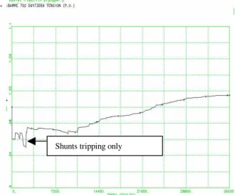
B. Loss of a single southern line at the LaVerendrye substation: figure 5
As specified in the design criteria, for this single line outage (N-1 incident), TDST does not operate. The switching of shunt elements by the MAIS devices is sufficient to avert voltage collapse.
Fig 5 Voltage(p.u.) at Duvernay 735 kV, simulation time 600 sec.
C. Loss of 2 northern lines at the Duvernay Substation: figure 6
This case demonstrates the combined operation of two fixed rules followed by the integral rule. The fixed rules respond quickly to the initial voltage drop, as per their design. As can be seen in Figure 6, this is insufficient to restore the voltage profile: the voltage keeps on decreasing. The integral rule then operates repeatedly until the system voltage profile is restored using a minimal amount of load shedding. This repeated action illustrates the closed-loop design of the integral rule.
Fig 6 Voltage (p.u.) at Boucherville 735 kV, simulation time 600 sec.
V. CONCLUSIONS
The installation and operation of TDST, an undervoltage
Shunts tripping only
Shunts tripping only (without TDST)
With TDST Load shedding
Load shedding by the integral rule
Voltage :0.95 p.u. With TDST
load shedding protection scheme, completes H-Q’s defense plan aimed at counteracting extreme contingencies. This SPS specifically addresses long-term voltage instability and collapse issues in the Montreal region. The use of the average voltage taken over five substations in the Montreal area enables the discrimination between single and multiple line outages. Different rules are ready to operate depending upon the severity of the disturbance. The amount of load to be shed to stabilize the network is controlled by a set of rules whose parameters have been optimized to deal with a variety of network configurations, power flows and incidents. Finally, the combination of fixed and integral rules enable to securely stabilize the network.
VI. ACKOWLEDGMENT
The methodology for optimizing the load shedding controller was set up and the preliminary tests on the Hydro-Québec system were performed by Dr. Cedric Moors, under the context of his Ph.D. at the University of Liège [5]. Achievement of TDST was made possible by the collaboration of a number of Hydro-Québec employees specializing in various technical aspects of power systems and engineering. We would like to thank them and particularly acknowledge the contribution of Laurent Soulières , Hydro-Québec Planning Department, Harold Ratté and Jocelyn Marcotte of the Hydro-Québec Engineering Department.
VII. REFERENCES
[1] C. W. Taylor, Power System Voltage Stability, McGraw Hill, EPRI Power System Engineering series, 1994
[2] T. Van Cutsem, C. Vournas, Voltage Stability of Electric Power Systems, Boston, Kluwer Academic Publishers, 1998
[3] C. W. Taylor, ``Concepts of undervoltage load shedding for voltage stability'', IEEE Trans. on Power Delivery, Vol. 7, pp. 480-488, 1992 [4] C. Moors, D. Lefebvre, T. Van Cutsem, ``Load Shedding Controllers
Against Voltage Instability: a Comparison of Designs'', Proc. of the IEEE Power Tech Conference, Porto (Portugal), 2001, ISBN 0-7803-7140-2 [5] C. Moors, On the Design of Load Shedding Schemes against Voltage
Instability in Electric Power Systems, PhD thesis, University of Liège, Fac. of Applied Sciences, October 2002
[6] D. Lefebvre, C. Moors, T. Van Cutsem, “Design of an undervoltage load shedding scheme for the Hydro-Québec system”, Proc. IEEE PES General Meeting, Toronto (Canada), July 2003
[7] S. Bernard, G. Trudel, G. Scott, ``A 735-kV shunt reactors automatic switching system for Hydro-Québec network'', IEEE Trans. on Power Systems, Vol. 11, pp. 2024-2030, 1996
[8] G. Trudel, S. Bernard, G. Scott, ``Hydro-Quebec's defense plan against extreme contingencies'', IEEE Trans. on Power Systems, Vol. 14, pp. 958-965, 1999