HAL Id: hal-00911527
https://hal.archives-ouvertes.fr/hal-00911527
Submitted on 2 Dec 2013
HAL is a multi-disciplinary open access
archive for the deposit and dissemination of
sci-entific research documents, whether they are
pub-lished or not. The documents may come from
teaching and research institutions in France or
abroad, or from public or private research centers.
L’archive ouverte pluridisciplinaire HAL, est
destinée au dépôt et à la diffusion de documents
scientifiques de niveau recherche, publiés ou non,
émanant des établissements d’enseignement et de
recherche français ou étrangers, des laboratoires
publics ou privés.
A Muscle Model for Enhanced Character Skinning
Juan Ramos, Caroline Larboulette
To cite this version:
Juan Ramos, Caroline Larboulette. A Muscle Model for Enhanced Character Skinning. Journal of
WSCG, University of West Bohemia, Czech Republic, 2013, 21 (2), pp.107–116. �hal-00911527�
A Muscle Model for Enhanced Character Skinning
Juan Ramos
Universidad Rey Juan Carlos Modeling and Virtual Reality Group
C/ Tulipàn, s/n 28933, Mòstoles, Spain [email protected]
Caroline Larboulette University of South Brittany
IRISA-UBS Lab Campus de Tohannic 56000, Vannes, France [email protected]
ABSTRACT
This paper presents a novel method for deforming the skin of 3D characters in real-time using an underlying set of muscles. We use a geometric model based on parametric curves to generate the various shapes of the muscles. Our new model includes tension under isometric and isotonic contractions, a volume preservation approximation as well as a visually accurate sliding movement of the skin over the muscles. The deformation of the skin is done in two steps: first, a skeleton subspace deformation is computed due to the bones movement; then, vertices displacements are added due to the deformation of the underlying muscles.
We have tested our algorithm with a GPU implementation. The basis of the parametric primitives that serve for the muscle shape definition is stored in a cache. For a given frame, the shape of each muscle as well as its associated skin displacement are defined by only the splines control points and the muscle’s new length. The data structure to be sent to the GPU is thus small, avoiding the data transfer bottleneck between the CPU and the GPU. Our technique is suitable for applications where accurate skin deformation is desired as well as video games or virtual environments where fast computation is necessary.
Keywords
Muscle, Skinning, Character Animation, Real-Time, GPU
1
INTRODUCTION
While the rendering of static scenes can now be so re-alistic that it is very often difficult to distinguish vir-tual images from real photographs, the same isn’t true for animation, especially for characters. Despite the tremendous progress that has been made, anybody can tell the difference between a video of a real person in movement and a 3D character animation. This is because a character is a complex object composed of many different parts in interaction and a character is familiar to human beings which leaves little room for inaccuracy.
It is common practice to decompose the animation of a character into two problems: the animation of the skele-ton and the animation of what’s around it. In this paper, we address the second one. By describing the individ-ual layers composing an object rather than just its sur-face, we believe that it is possible to generate more ac-curate deformations of the outside skin layer.
Permission to make digital or hard copies of all or part of this work for personal or classroom use is granted without fee provided that copies are not made or distributed for profit or commercial advantage and that copies bear this notice and the full citation on the first page. To copy otherwise, or re-publish, to post on servers or to redistribute to lists, requires prior specific permission and/or a fee.
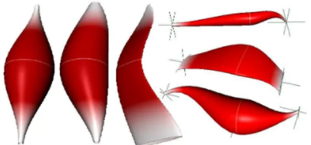
Figure 1: Various muscle shapes generated with our Maya plugin. From left to right: original template shape; non-linear sweeping spline; flat muscle; arbi-trary muscles. The white line shows the position of the muscle belly center C.
Anatomically based models have first been intro-duced to Computer Graphics in 1992 by Chen and Zeltzer [Che92a] who modeled an accurate frog’s muscle using finite elements. Subsequent simpler models have then been used with the sole goal of enhancing 3D characters’ skin deformation through the animation of individual muscles. In contrary to what happens in real life, they deform as a response to bone deformation and their only purpose is to obtain visually more appealing deformations. Although that approach has been used for movie production (Shrek, Lord of the Rings [Gra]) and is included in recent versions of
Autodesk Maya Software [May13a] it has remained computationally too expensive and too difficult to set up for a wider use including video games or virtual environments. We propose a new muscle model that addresses both problems.
We do not intend to model dynamic effects or wrinkles that can be added as additional layers [Cap02a, Lar04a]. We do however provide a tension parameter that may be used to control a soft tissues dynamics simulation such as [Jam02a, Lar05a]. These additional layers are outside the scope of this paper that aims at presenting the muscle model and it’s GPU implementation. Our muscle model is defined by a few parameters that allow artists to express complicated shapes (see figure 1). Although it is best suited for fusiform and multipennate (broad origins and insertions) muscle shapes, multi-belly muscles such as the pectoralis mayor or the trapezius can be generated by grouping several fusiform shapes like in [Sch97a].
Animating muscle deformation as a response to bone movement has the advantage that it resembles the way artists work, but this implies that skin deformation due to the tension of the underlying muscles is not taken into account. To overcome this problem, we intro-duce a muscle tension parameter allowing the muscle to change the shape of its cross-section while preserv-ing its overall volume. In addition, we achieve a slid-ing behavior of the skin over the muscles by restrict-ing the displacement of each skin vertex to directions perpendicular to the muscles’ fibers which visually im-proves the results obtained by previous geometric mod-els where the skin vertices were rigidly attached to the muscles primitives.
To address the challenges of accurately animating anatomically based character models in real-time, we introduce (1) a new parametric fusiform muscle model capable of both isometric and isotonic contraction that preserves its overall volume (section 3), (2) a new geometric algorithm for skin deformation that achieves skin sliding behavior without the high cost of a physically based simulation (section 4), and (3) a GPU implementation of our model including normal correction that is suitable for use in video games (section 5). We achieve frame rates of 25 Hz on a dual core 3.0 GHz Pentium 4 PC equipped with a GeForce 8800 GTX graphics board for 25 instances of a mesh composed of 82000 triangles and 56 muscles, which represents a computational overhead of 20− 25% compared to a smooth skinning only.
2
RELATED WORK
The modeling and animation of individual muscles has been an extensive topic of research for a few decades. For a comprehensive state-of-the-art, the reader may re-fer to [Lee12a].
Previous work range from anatomically accurate models to models only vaguely faithful to the real anatomy. On the one hand, we find the muscle models that serve as a mean to move the bones of the skeleton. Because they are difficult to control in their actual state, those models are still marginal although they continue to receive some attention [Lee06a]. A complete biomechanical model of the upper body can be found in [Lee09a]. On the other hand, we find techniques that try to mimic some muscle deformation of the skin although either no individual muscle is de-fined [Wan02a, Moh03a, Cap07a] or the muscles do not correspond to real ones [Pra05a]. The skinning based techniques give nice results provided the user designs accurate input shapes [Wan02a]. However, with only anisotropic scaling [Cha89a, Wan02a, Moh03a] along X, Y and Z-axis, it is very difficult to obtain realistic muscle deformations. [Wan07a, Web07a, San08a] present data driven techniques for synthesizing skin deformations from skeletal motion. While the results produced are definitely more accurate, those techniques require a set of examples and thus cannot be applied to characters that need exaggerated deformations or for movements the actor did not perform or the animator did not create.
The alternative is to define individual muscles that serve as a mean to deform the outer skin layer but do not con-trol the bones and the skeleton movement like in reality. Our work fits into this paradigm. In 1997, Wilhelms and Scheepers et al. [Wil97a, Sch97a] both proposed a first generic muscle model based on ellipsoids. While the results were visually appealing at that time, there were several limitations to the model. Firstly, the shape of the muscle belly and of the tendons was constrained to elliptical ones which made it hard to cover all of the body muscles, and even the biceps and triceps of the arm could not be correctly approximated. Subsequent parametric models [Wil97b, Lee07a] tried to solve the setup problem. Parametric muscles that have been de-signed for one character are easy to re-use onto another character as only a few scalings need to be done. Our muscle model is also based on the idea that only a small set of parameters is sufficient to create a wide variety of shapes. Moreover, unlike [Lee07a], our parameteriza-tion is suitable for a GPU implementaparameteriza-tion.
More recently, physically based models of muscles have been investigated. Whether they are based on mass-spring systems [Ned00a, Aub00a], finite elements methods [Zhu98a] or finite volume meth-ods [Ter03a, Ter05a] they are difficult to set up and several orders of magnitude slower than the model we propose. In addition, the muscle shape is defined by either a polygonal mesh or a volumetric decomposition in tetrahedra which is totally unsuitable for the modern GPU pipelines.
To deform the skin and obtain a sliding effect of the skin over the muscles, [Wil97b] uses masses and springs to model the skin as well as to anchor the skin to the under-lying muscles and bones. While this gives pleasing re-sults, this step is very heavy in terms of setup (stiffness and damping coefficients) and computation. Turner et al. [Tur93a] use a physically based simulation of elas-ticity to deform an elastic skin. We avoid the heavy cost of a physically based simulation by proposing a new geometric algorithm to displace the vertices of the skin as a response to the muscles deformation, which al-lows sliding effects. This is an improvement compared to other geometric models where the skin is rigidly an-chored to underlying components [Wil97b, Lee07a].
3
OUR MUSCLE MODEL
Similar to previous models [Wil97b, Ned00a, Aub00a, Lee07a], we make the assumption that the force exerted by the muscle follows a fictive action line A(t) that lies on the main axis of the muscle shape. This action line is anchored to the bones at the origin and insertion points, thus elongating and shortening as the skeleton moves. The muscle belly is attached through deformable ten-dons at both ends.
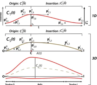
Overview The general shape of our muscle model is a modified generalized cylinder defined by the sweep of a thickness curve CT(t) along a sweeping curve CS(t). CS(t) is a three-dimensional spline representing the pro-file of the muscle. It is defined by two 3D points: the origin O and insertion I. CT(t) is a one-dimensional function representing the muscle’s thickness as a func-tion of t. The muscle’s cross-secfunc-tion at t is thus de-fined as an ellipse placed along CS(t) whose thickness is given by CT(t) and a scaling factor sf. sfis applied in a user-chosen direction−→Sd perpendicular to the action line. This scaling is only applied to the sections, not to the spline curves. See figure 2 for a sketch.
To avoid intersections between sections and to simplify the volume conservation computation detailed in sec-tion 3.2.1, the secsec-tions do not follow the curvature of CS(t) but are always perpendicular to the action line A(t).
Modeling We have implemented a Maya plugin that allows the user to modify the curves control points, the scaling factor sfas well as the scaling direction−Sd. As→ we will see in section 3.1, the control points are con-strained and cannot be freely moved, which reduces the number of variables to control. In addition, the muscle belly center C can be displaced along the segment OI. It is thus possible to obtain a wide variety of asymmet-rical shapes. See figure 1 for examples.
3.1
Shape Computation
CS(t) and CT(t) Bézier curves defining the muscle shape are each composed of two cubic spline segments
Figure 2: Top: thickness curve CT(t) ; center: sweep-ing curve CS(t) ; bottom: muscle’s longitudinal section resulting from the sweeping of CT(t) along CS(t) with CS(t) represented in dashed line.
COS(ˆt), CI
S(ˆt) and CTO(ˆt), CIT(ˆt) respectively called origin and insertion segments, joined with G1 continuity. Mapping between t and ˆt is explained later. CT(t) is a piecewise one-dimensional function which represents the varying thickness of the muscle at a parametric point t∈ [0,1] along CS(t).
Each Bézier cubic spline segment is defined by four control points pj, j ∈ [0,3] and the cubic Bernstein polynomials B3j(ˆt) by: C(ˆt) = ∑3j=0pjB3j(ˆt) = (1 − ˆt)3p 0+ 3ˆt(1 − ˆt)2p1+ 3ˆt2(1 − ˆt)p2+ ˆt3p 3 (1)
Henceforward we will write pO0−3 and pI0−3 the four control points of the origin and insertion spline seg-ments respectively, regardless of their dimension. G1continuity is obtained by merging pO
3 and pI0 and aligning pO2, pO3 and pI1in the cubic spline segments for both the thickness and the sweeping curves (see figure 2). pO
0, pO1, pI2 and pI3 can take any arbitrary values chosen by the user.
The action line A(t) defined by the origin O and the insertion I of the muscle can be expressed by the fol-lowing parametric equation:
A(t) = O + t(I − O) t ∈ [0,1] (2) Let−→S be the unit vector perpendicular to both−→Sd and A(t): − → S = −→ OI×−Sd→ %−OI→×−Sd→% (3)
The orthogonal basis B= {−→S ;−→Sd;−OI→} defines the sec-tion space. Each of CS(t) control points, pO
S,0−3 and pI
S,0−3, can be defined in section space by projecting them onto B orthogonal vectors.
Efficient skin vertices displacement as a response to muscles deformation such as described in section 4.2 relies on having a direct mapping of the parametric space of the action line onto the parametric space of the spline segments. This is simply obtained by making lo-cal Bézier parameter ˆt linearly dependent on t. Thanks to the linear precision property of the Bézier spline, uni-formly distributed control points on a straight line pro-duce that straight line:
n
∑
j=0 j nB n j(t) = t (4)In our case n= 3. The control points pO
S,0−3on COS(t) are spaced by%−→OC%/3 along its t coordinate and the control points pI
S,0−3on CS(t) are spaced by %I −→ CI%/3. In section space,−OI coordinate is t, so p→ O
S,0−3and pIS,0−3 positions can be expressed with only two coordinates plus t.
Let C= A(tc) be the muscle belly center such as tc= %−→OC%/%−OI→%. The local ˆt is obtained by:
ˆt = ! t/tc if t<= tc, (t −tc)/(1 −tc) if t > tc. (5) and used in CSO(ˆt), CO T(ˆt) and CSI(ˆt), CTI(ˆt) respectively to define the shape of the muscle as a function of t along the action line.
3.2
Muscle Deformation
Muscle is an incompressible, anisotropic, hyper-elastic material that undergoes two types of contractions: iso-tonic and isometric. In both cases, the overall volume of the muscle remains roughly constant [Wil97b]. In the case of an isotonic contraction, the bones move but the tension of the muscle remains constant. The change in shape is thus only due to the shorten-ing/elongation of the muscle. If it shortens, the belly of the muscle bulges. It decreases in the other case. The action line, anchored to the bones at O and I, changes length as the skeleton moves. In order to preserve the volume of the muscle, we recompute the new belly thickness while keeping tendons thicknesses constant. This is detailed in section 3.2.1.
In the case of an isometric contraction, the bones do not move and the muscle length doesn’t change. However, the shape of the muscle is modified. When the tension increases, the muscle bulges in one direction while nar-rowing in the perpendicular dimension. Tendons also
bulge in the same direction and become more visible. The muscle and the tendons all relax to the rest state when the tension decreases. Again, the overall vol-ume of the muscle remains constant. This is achieved through a tension parameter tension that allows the muscle to scale in the direction−Sd→chosen by the artist. The inverse of that scale is applied in the perpendicular direction−→S . This is detailed in section 3.2.2.
In real life, both types of contraction happen at the same time. First, the tension of the muscle increases. When it reaches a certain threshold, the bones start moving while the tension decreases until the bones reach the new position. By moving the bones and varying the tension parameter of our model, it is possible to achieve this natural behavior.
3.2.1
Volume Preservation
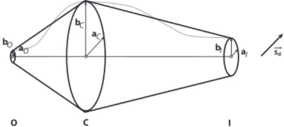
As muscle sections are parallel to each other along the sweeping curve, two consecutive sections form the el-liptic bases of an oblique truncated cone of height the distance between the two sections. The volume of the muscle is thus equal to the sum of an infinite number of such cones of infinitely small height. The volume of an oblique truncated cone is the same as the one of a right cone, therefore we can compute the volume as if CS(t) were straight and equal to A(t).
Cone volume computation is costly and we have found that a very coarse discretization of the muscle’s volume in only two truncated elliptic cones was a good and very stable approximation (see figure 3). Indeed, it is more important to keep the differential volume error low be-tween the different muscle states (elongated, rest, com-pressed) rather than having an exact volume. For the muscles we used in our demos, we have measured an er-ror of 10% in average with respect to the exact volume computation but only a 1% error deviation between ex-treme muscle states (150% elongated, 50% shortened). This means that the volume remains constant with an error of only 1%, which is negligible.
Let(aX, bX) be the axes of the three ellipses defining the two cones at the origin O, center C, and insertion I points. The aX axes are aligned with the scaling direc-tion−→Sd and their length is aX. bX axes are perpendic-ular to the aX ones and their lengths bX are defined as bO= pOT,0, bC= pT,3O = pIT,Oand bI= pIT,3. The ratios aX/bX= sf.
The total volume of the muscle is computed by equa-tion (6) which, divided by sf, results in equaequa-tion (7).
V = %−→OC%π"2aCbC+aCbO+aObC+2aObO 6 # + %−CI→%π"2aCbC+aCbI+aIbC+2aIbI 6 # (6) V = π sf 3 (% −→ OC%(bC2+ bO2+ bCbO) + %−CI→%(bC2+ bI2+ bCbI)) (7)
The initial volume is computed at rest state. To keep a constant volume as well as a constant thickness for the tendons (desired feature for muscles deforming un-der isotonic contraction), bC needs to be recomputed at each timestep. From (7), we obtain a quadratic equation AbC2+ BbC+C = 0 with: A= %−OI→% B= %−→OC%bO+ %−CI→%bI C= %−→OC%bO2+ %CI−→%bI2−3Vπ sinitial f (8)
It can be solved by taking its positive solution bC′= −B+√δ
2A with δ= B2− 4AC.
As mentioned in section 3.1, to keep the belly shape continuous, pOT,2, pOT,3 and pIT,1 must be kept collinear as bC changes and the slope of segment pOT,2pIT,1must also be kept constant.
C O I bC bO bI aC aO a I Sd
Figure 3: The volume of the muscle is approximated by the volume of two elliptic cones defined by(O, aO, bO), (C, aC, bC) and (C, aC, bC), (I, aI, bI).
3.2.2
Tension Parameter
From equation (7) it is straightforward that to maintain a constant volume, the scaling factor sfshould be kept constant. As sf= aX/bX, this can be achieved by mul-tiplying axes lengths aXby tension while dividing axes lengths bXby the same amount at the origin, center and insertion points.
The new axes lengths ˜aX and ˜bX when the muscle is under isometric contraction can thus be expressed as follows:
˜aX= aX∗ tension
˜bX= bX/tension (9) Figure 4 shows a muscle in isometric contraction for different values of the tension parameter. At rest state (left), tension= 1. The muscle is under tension for tension> 1, and, for increasing values of tension, the muscle bulge is more noticeable (middle and right). At any time during animation, both types of contraction are involved. The volume of the muscle is preserved by first applying equation (7) that accounts for changes in length of the action line, then equation (9) that takes the strain into account.
Figure 4: Varying tension parameter. From left to right: tension= 1, tension = 1.15 and tension = 1.3.
4
SKIN DEFORMATION &
RENDER-ING
The skin/clothes layer is the only visible layer on a character. The muscles serve as an underlying tool to help deform the skin in a more accurate way. We use a two-steps approach. First, the skin layer is modi-fied using a linear blend skinning as a response to the skeleton’s movement. Note that other skinning tech-niques [Kav05a, Kav07a, Kav08a] can be used. The skin layer is subsequently deformed as a response to the muscles deformation by applying a displacement to each influenced vertex. We perform this step on the GPU.
The way a muscle deforms the surrounding skin is cru-cial to obtain good results. As the relationship between the skin and the muscle can be very different depend-ing on the part of the body affected, we introduce a weighted deformation scheme as well as a fat layer that allow the animator to adjust the skin deformation. The fat layer is in charge of keeping a distance between the skin and the underlying muscle and more or less attenu-ates the deformation due to the muscle bulging depend-ing on the chosen weightdepend-ing system (section 4.1). To achieve a skin sliding behavior over the muscles, we propose a vector oriented vertices displacement (sec-tion 4.2).
4.1
Muscle Influence
A skin vertex is influenced by a muscle if it lies in its neighborhood. This influence together with an associ-ated weight are evaluassoci-ated at the bind pose. In exist-ing commercial programs or muscle-dedicated plugins the user paints the vertices influences by hand for each muscle. We provide an automatic way to assign nor-malized weights varying from 0 to 1 to skin vertices, a weight of 0 meaning no influence at all, and 1 meaning full muscle influence.
The influence computation is achieved by projecting perpendicularly each vertex of the concerned limb Vi onto the action line A(t) of each muscle. If the projec-tion point lies outside OI, then this particular vertex is not influenced by the muscle. In the other case the mus-cle’s influence depends on a neighborhood template as-signed by the user.
We provide three neighborhood templates:
Radial template: all of the vertices that lie within a given distance from the action line are influenced. Half-space template: all of the vertices that lie on the upper side of the plane defined by the action line and having−→Sdas a normal are influenced.
Fitted template: similar to the half-space template but with the additional restriction that the ray(Vi, −−→Sd) must intersect the muscle shape for the vertex Vito be influenced.
The user chooses a template depending on how he wishes the skin to be influenced by the muscle. Exam-ples of the three templates are shown on figure 5, top row, for a given muscle.
If the vertex Viis influenced by the muscle, its weight wi is obtained depending on an automatic weighting system chosen by the user. We have implemented two of them:
Binary weighting system: the weight wiof Viis set to 1 if the vertex Viis influenced by the muscle and 0 in the other case.
Spline-based weighting system: the weight is ob-tained by dividing the muscle thickness CT(t) at Viby max(pO
T,2, pOT,3, pIT,1). We obtain weights wi∈ [0,1] that depend on the local thickness of the muscle.
These weighting systems must be used depending on the expected deformation of the muscle on the skin (see figure 5, bottom row). The first one is indicated for very fitted zones with almost no fat, so the tendons can be seen as well as almost the whole shape of the mus-cle. Note that the skin deformation is continuous and smooth because the muscle shape is G1continuous and the skin follows that shape. The second one attenuates the deformation of the skin with respect to the previ-ous one, and is indicated for fatty zones were only a small bulge due to the muscle is expected. The com-puted weights are also smooth, so the deformation re-mains continuous.
Figure 5: From left to right: radial influence template, half-spacetemplate, and fitted template. Top row shows the corresponding binary weights while bottom row shows the spline-based weights.
4.2
Skin Vertices Displacement
Vector oriented displacement makes the skin slide over the muscles by preserving a distance between them
without rigidly anchoring the skin vertices to the mus-cles’ primitives. To explain the deformation technique we first suppose that there is no fat layer and that all ver-tices have a weight of 1. It results in the skin being dis-placed to fit the muscles surfaces. How the fat layer and weights affect the vertices displacement is explained in section 4.3.
Let Vi be the current skin vertex we want to displace onto the muscle’s surface V′i. This vertex is displaced in−→Sddirection defined by the user as the main direction of bulging.
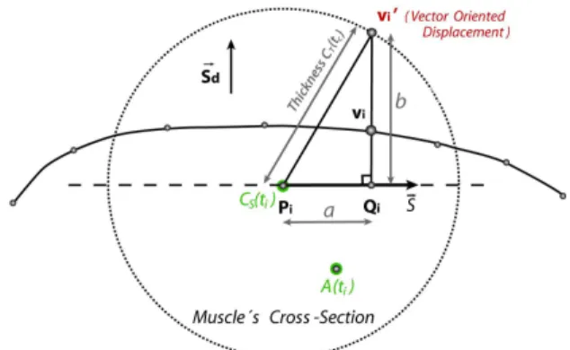
Figure 6: Skin vertices displacement algorithm: Viis displaced in order to lie on the muscle’s surface at V′i.
The algorithm works as follows (see figure 6): we first compute Pi = CS(ti) as the central point of a muscle section on CS(t) curve. The muscle’s section on which we solve the intersection now contains Piand Vi. Let CT(ti) be the thickness of the muscle at the point Pi and−→S be the unit vector perpendicular to both the ac-tion line A(t) and the displacement vector−Sd→(see equa-tion (3)).
The point Qiis defined as the projection of Vionto−→S . The distance from Pito Qican simply be expressed as a=−−→PiVi·−→S . Because a and b (see figure 6) form a right triangle, the new position of vertex Viis given by the two following equations:
b=$CT(tc)2− a2 (10) V′i= Qi+−→Sdb (11) At this point we have found V′i for a circular muscle section. To make the algorithm work with elliptical sec-tions we only have to multiply b by sfand tension.
V′i= Qi+−→Sd· b · sf· tension (12)
4.3
Fat Layer and Weighted Deformation
We have introduced vertex weights wi ∈ [0,1] in sec-tion 4.1 to attenuate the effect of muscles on the de-formation of the skin. In the case where no fat layer
exists, those weights directly influence the vertex dis-placement||−−−→ViV′i||. The new vertex position V′′i is thus given by:
V′′i = Vi+−−→ViV′iwi (13)
However, muscles can deform the skin through a fat layer. Our implementation of the fat layer consists in calculating a distance Lfatbetween the muscle and the skin at bind pose and keeping it constant during anima-tion. To keep distance consistency Lfat must measure vector oriented distance to the muscle.
In that case, the weights wiare applied to the fat layer offset Lfatand the new vertex position V′′i is given by:
V′′i = Vi+ −−→ ViV′i ||−−→ViV′i|| (||
−−→
ViV′i|| + Lfatwi) (14)
4.4
Normal Correction
Visual appearance of 3D characters is dramatically im-proved by using several textures for diffuse lighting, bump mapping, and specular mapping. To apply those algorithms, it is necessary to have the normal and bi-normal vectors for each mesh vertex. When a muscle displaces a vertex Vi into a new position, the normal −
→
Niobtained from the previously applied bone skinning technique must be recomputed (see figure 7).
Figure 7: Left: displaced wireframe mesh; center: same mesh with texture applied but no normal correction; right: same mesh with texture and normal correction. As the normals of the muscle shape can’t be directly mapped to the skin due to the fat layer and influence weighting, the ideal solution is to recompute the skin normals from vertex adjacency data. Current GPUs only have edge adjacency available at the input of the pipeline, so we have used a pre-calculated buffer that contains the adjacency information for each vertex. The character deformation is divided into two passes: the first pass computes the mesh deformation due to the skinning and the muscles; and the second pass renor-malizes the normals by looking up in the adjacency buffer and computing regular per vertex normals. We need to recalculate the normals for the entire mesh as skeleton subspace transformed normals are different (see figure 8).
Figure 8: Arm example without muscles. Left: skele-ton subspace normals calculation for the whole mesh; center: a discontinuity can be seen when using differ-ent normal calculation algorithms; right: normal calcu-lation mask used in the central picture: in black, GPU skeleton subspace normals calculation; in grey, renor-malization by computing normals per vertex.
5
GPU IMPLEMENTATION AND
RE-SULTS
We have implemented the vertices displacements due to muscle deformation on a vertex program on the GPU. Two key points make our implementation run in real-time: the use of a parametric muscle model that needs to send little data to the GPU per frame, and the dis-cretization of the Bézier spline basis to avoid high com-putational cost.
5.1
CPU-GPU data transfer
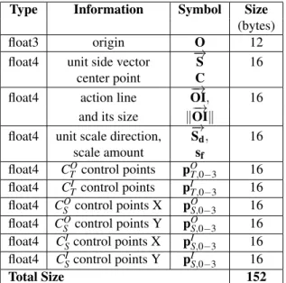
Muscle volume preserving and movement due to the skeleton animation is calculated on the CPU while the vertex bone skinning, muscle displacement and normal correction are computed on the GPU. Table 1 lists the data sent per animation timestep to the GPU for each muscle. While some of this data is redundant for reduc-ing the amount of computation on the GPU, the total size is of only 10 vectors per muscle per frame.
Type Information Symbol Size (bytes) float3 origin O 12 float4 unit side vector −→S 16
center point C
float4 action line −OI,→ 16 and its size %−OI→%
float4 unit scale direction, −Sd,→ 16 scale amount sf float4 CO T control points pOT,0−3 16 float4 CI T control points pIT,0−3 16 float4 CO S control points X pOS,0−3 16 float4 CO S control points Y pOS,0−3 16 float4 CI Scontrol points X pIS,0−3 16 float4 CSIcontrol points Y pIS,0−3 16
Total Size 152
Table 1: Size, in bytes, of the data sent to the GPU per muscle, per frame.
CT(t) control points are one-dimensional and can be stored in 2 vectors. CS(t) three-dimensional control
points need 6 vectors. By using the linear precision property (see equation (4)) we can save memory space by encoding pOS,0−3and pIS,0−3 points in the 2D basis B= {−→S ;−→Sd}, the missing dimension is implicitly de-fined by keeping a constant distance between pOS,0−3and pI
S,0−3as described in section 3.1. The B basis is very efficient as the majority of GPU calculations are done in section space.
Data containing the index of the muscle influencing each vertex and the associated fat offsets Lfat is sent to the GPU only once with the rest of per-vertex data.
5.2
Bézier Spline Basis Discretization
To speed-up the computation of C(ˆt) (see equation (1)), we store the basis functions of the spline on the GPU in an array of size n. We discretize the basis for n values tiof ˆt and we store the results in[1 × 4] vectors of the form:
[B30(ti), B31(ti), B32(ti), B33(ti)] (15) In practice, we have found n= 100 and ti= 1/n to pro-duce smooth deformations. Increasing the discretiza-tion only increases the buffer’s size but has no influence on the computation time and doesn’t visually improve the results.
During animation, the projection of each vertex Vionto the action line A(t) gives the value of t for this vertex. We obtain ˆt from equation (5). The thickness at ˆt is the result of the dot product of the closest ti spline basis vector we have previously stored with vector pOT,0−3if t<= tcand pI
T,0−3otherwise. CS(t) in B basis is com-puted in a similar way for each of the two dimensions. Having CT(t) and CS(t) we compute V′i by applying equation (12). The final skin deformation is calculated with equation (13) or (14). All these computations are performed on the GPU.
5.3
Results
All of the timings and animations presented in this sec-tion have been computed on a dual core 3.0 GHz Pen-tium 4 PC equipped with a GeForce 8800 GTX graphics board under Windows Vista using the DirectX 10 API.
5.3.1
Male Gymnast
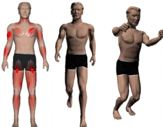
We have tested our algorithm on a male gymnast walk-ing and jumpwalk-ing. The model is composed of 82000 triangles. We have attached 56 muscles to the arms, legs, chest and neck of the character (see figure 9). It took about a day for a non-skilled animator to shape the muscles, attach them to the bones and choose appro-priate skin influence templates. Note that the number of triangles greatly exceeds the one of standard meshes used in regular video games. This is due to the fact that
higher resolution meshes are needed to correctly appre-ciate the muscles’ influences. We obtain real-time for as many as 25 characters, which corresponds to a total of 1400 muscles animated using both isometric and iso-tonic contractions. We observe a loss of 20−25% in the frame rate due to the use of muscles (17 fps) compared to the use of a linear blend skinning only (26 fps).
Figure 9: From left to right: male gymnast model com-posed of 82K polygons and 56 muscles (setup time about 8 hours); 2 frames from the GPU real-time an-imation.
5.3.2
Dinosaur Leg
We have also tested our algorithm on a simple dinosaur leg. The model is composed of 7800 triangles to which we have added 4 muscles (see figure 10).
Figure 10: Two frames of the dinosaur leg animation. From left to right: design of 4 muscles under Maya (setup time about 20 min); Animation on GPU without muscles; Animation on GPU with muscles.
5.3.3
Crowd Animation
Finally, we have tested our GPU algorithm on wider crowds (see figure 11). Up to 200 instances for a total of 11200 muscles could be animated in interactive time. Note that no GPU instancing technique was used.
Figure 11: Crowd animation of 100 instances of the male character which corresponds to 5600 muscles to-tal. Frame rate is 4.3 fps mainly limited by the high number of polygons: 8.2 millions.
Table 2 shows the frame rates obtained for different numbers of instances used for the man and dinosaur leg models. Mesh # Total # Fps of Instances of Muscles Man (82K tri.) 20 1120 21 Man (82K tri.) 25 1400 17 Man (82K tri.) 50 2800 9 Man (82K tri.) 100 5600 4.3 Man (82K tri.) 200 14000 2.1 Leg (8K tri.) 100 300 32 Leg (8K tri.) 200 600 16 Leg (8K tri.) 400 1200 3.5 Table 2: Frames per second per animation for both models and a number of instances varying from 20 to 400.
6
CONCLUSION AND FUTURE
WORK
We have presented a new parametric muscle model suit-able for real-time character animation as well as a new skin vertices displacement algorithm as a fast alterna-tive to physically based simulation of elasticity. Our model is suitable for both procedural animation and GPU animation. The user is provided with 2 spline curves that allow them to design a wide range of pos-sible muscles shapes. We have thus reached our goals of accuracy, efficiency and user’s usability. Compared
to previous muscles models, our model is complete in the sense that all kinds of skeletal muscles can be gen-erated (fusiform and flat); the skin layer is not rigidly attached to the muscles but slides over them without re-quiring the heavy cost of a physically based simulation; both isometric and isotonic contractions can be simu-lated thanks to our tension parameter; when deform-ing, the muscle preserves its volume; we offer a normal correction; our algorithm is suitable for Graphics Hard-ware.
Currently, there are two limitations to our work. The first one is that there is no muscle or muscle-bone interaction. While it may seem incorrect from an anatomical point of view, it may easily be overcome by the fact that the anchor points of our muscles do not need to be onto the bone. It is thus possible to keep the anchor points, hence the action line, from a certain distance to a bone or a muscle, which acts as if there were interactions. The important muscles to be mod-eled are the ones on the surface because they influence the outside appearance of the skin.
The second shortcoming is the modeling time. While adding muscles following an anatomy book is achiev-able by most users, it still takes some time to shape the muscles. One of our future work is to use medical data [Ter05a] to compute the initial shape of our mus-cles and provide retargetting, especially for characters of the same species.
In addition, we plan on combining our model with a model for dynamics of soft tissues whose behavior will be controlled though our tension parameter (when mus-cles are tense, the surrounding tissues jiggle less and vice-versa). We believe it should not be directly part of the muscle model because dynamics is not only due to the muscles, but also to fatty tissues. Last but not least, we would like to address the problem of automatically computing the tension of all of the muscles of a charac-ter given its animation through inverse dynamics.
7
REFERENCES
[Aub00a] A. Aubel and D. Thalmann. Realistic defor-mation of human body shapes. In Proceedings of Computer Animation and Simulation 2000, pages 125–135.
[Cap02a] S. Capell, S. Green, B. Curless, T. Duchamp, and Z. Popovi´c. Interactive skeleton-driven dy-namic deformations. In Proceedings of SIG-GRAPH’02, ACM ToG, 21(3), pages 586–593. [Cap07a] S. Capell, M. Burkhart, B. Curless, T.
Duchamp, and Z. Popovi´c. Physically based rig-ging for deformable characters. Graph. Models, 69(1):71–87, 2007.
[Cha89a] J. E. Chadwick, D. R. Haumann, and R. E. Parent. Layered construction for deformable
animated characters. In Proceedings of SIG-GRAPH’89, ACM Computer Graphics, 23(3), pages 243–252.
[Che92a] D. T. Chen and D. Zeltzer. Pump it up : Computer animation of a biomechanically based model of muscle using the finite element method. Computer Graphics, 26(2), 1992.
[Gra] Z. Gray and M. Hutchinson. Pro-cedural muscle and skin simulation. http://www.fourthdoor.com/muscle/.
[Jam02a] D. L. James and D. K. Pai. Dyrt: Dynamic response textures for real time deformation sim-ulation with graphics hardware. In Proceedings of SIGGRAPH’02, ACM ToG, 21(3), pages 582– 585.
[Kav05a] L. Kavan and J. Zara. Spherical blend skin-ning: A real-time deformation of articulated mod-els. In ACM SIGGRAPH Symposium on Interac-tive 3D Graphics and Games 2005, pages 9–16. [Kav07a] L. Kavan, S. Collins, J. Zara, and C.
O’Sullivan. Skinning with dual quaternions. In ACM SIGGRAPH Symposium on Interactive 3D Graphics and Games 2007, pages 39–46. [Kav08a] L. Kavan, S. Collins, J. Zara, and C.
O’Sullivan. Geometric skinning with approx-imate dual quaternion blending. ACM Trans. Graph., 27(4), 2008.
[Lar04a] C. Larboulette, M.-P. Cani. Real-Time Dy-namic Wrinkles. In Proceedings of Computer Graphics International 2004, pages 522–525. [Lar05a] C. Larboulette, M.-P. Cani, and B. Arnaldi.
Dynamic skinning: Adding real-time dynamic effects to an existing character animation. In Proceedings of Spring Conference on Computer Graphics 2005, pages 87–93.
[Lee06a] S.-H. Lee and D. Terzopoulos. Heads up! biomechanical modeling and neuromuscu-lar control of the neck. In Proceedings of SIG-GRAPH’06, ACM ToG, 25(3), pages 1188–1198. [Lee07a] K. S. Lee and G. Ashraf. Simplified muscle dynamics for appealing real-time skin deforma-tion. In Proceedings of International Conference on Computer Graphics and Virtual Reality, 2007. [Lee09a] S.-H. Lee, E. Sifakis, and D. Terzopoulos.
Comprehensive biomechanical modeling and sim-ulation of the upper body. ACM Trans. Graph., 28(4):99:1–99:17, 2009.
[Lee12a] D. Lee, M. Glueck, A. Khan, E. Fiume, and K. Jackson. Modeling and simulation of skeletal muscle for computer graphics: A survey. Found. Trends. Comput. Graph. Vis., 7(4):229–276, 2012. [May13a] Maya. Autodesk, 2013.
[Moh03a] A. Mohr and M. Gleicher. Building
effi-cient, accurate character skins from examples. In Proceedings of SIGGRAPH’03, ACM ToG, 22(3), pages 562–568.
[Ned00a] L. P. Nedel and D. Thalmann. Anatomic modeling of deformable human bodies. The Vi-sual Computer, pages 306–321, 2000.
[Pra05a] M. Pratscher, P. Coleman, J. Laszlo, and K. Singh. Outside-in anatomy based character rig-ging. In Proceedings of the ACM SIGGRAPH / Eurographics Symposium on Computer Anima-tion, 2005.
[San08a] S. I. Park and J. K. Hodgins. Data-driven modeling of skin and muscle deformation. ACM Trans. Graph., 27(3):1–6, 2008.
[Sch97a] F. Scheepers, R. E. Parent, W. E. Carlson, and S. F. May. Anatomy-based modeling of the human musculature. In Proceedings of SIGGRAPH’97, ACM Computer Graphics, pages 163–172. [Ter03a] J. Teran, S. Blemker, V. Ng Thow Hing, and
R. Fedkiw. Finite volume methods for the simu-lation of skeletal muscle. In Proceedings of ACM SIGGRAPH / Eurographics Symposium on Com-puter Animation, 2003.
[Ter05a] J. Teran, E. Sifakis, S. S. Blemker, V. Ng-Thow-Hing, Cynthia Lau, and Ronald Fedkiw. Creating and simulating skeletal muscle from the visible human data set. IEEE Trans. on Visualiza-tion and Comp. Graph., 11(3):317–328, 2005. [Tur93a] R. Turner and D. Thalmann. The elastic
surface layer model for animated character con-struction. Proceedings of Computer Graphics International’93, pages 399–412.
[Wan02a] X. C. Wang and C. Phillips. Multi-weight enveloping: least-squares approximation tech-niques for skin animation. In Proceedings of SCA’02, pages 129–138.
[Wan07a] R. Y. Wang, K. Pulli, and J. Popovi´c. Real-time enveloping with rotational regression. ACM Trans. Graph., 26(3):73, 2007.
[Web07a] O. Weber, O. Sorkine, Y. Lipman, and C. Gotsman. Context-aware skeletal shape deforma-tion. Computer Graphics Forum, 26(3), 2007. [Wil97a] J. Wilhelms. Animals with anatomy. IEEE
Computer Graphics and Applications, 17(3):22– 30, 1997.
[Wil97b] J. Wilhelms and A. Van Gelder. Anatom-ically based modeling. In Proceedings of SIG-GRAPH’97, ACM Computer graphics, pages 173–180.
[Zhu98a] Q. H. Zhu, Y. Chen, and A. Kaufman. Real-time biomechanically-based muscle volume de-formation using fem. Computer Graphics Forum, 17(3):275–284, 1998.