HAL Id: hal-00867681
https://hal-iogs.archives-ouvertes.fr/hal-00867681
Submitted on 30 Sep 2013
HAL is a multi-disciplinary open access
archive for the deposit and dissemination of
sci-entific research documents, whether they are
pub-lished or not. The documents may come from
teaching and research institutions in France or
abroad, or from public or private research centers.
L’archive ouverte pluridisciplinaire HAL, est
destinée au dépôt et à la diffusion de documents
scientifiques de niveau recherche, publiés ou non,
émanant des établissements d’enseignement et de
recherche français ou étrangers, des laboratoires
publics ou privés.
Intracavity gain gratings
Aurélie Moreau, Quiong He, Isabelle Zaquine, Alain Maruani, Robert Frey
To cite this version:
Aurélie Moreau, Quiong He, Isabelle Zaquine, Alain Maruani, Robert Frey. Intracavity gain gratings.
Optics Letters, Optical Society of America - OSA Publishing, 2007, 32 (3), pp.208210. �hal-00867681�
Intracavity gain gratings
Aurélie Moreau, Qiong He, Isabelle Zaquine, and Alain Maruani
GET/Télécom Paris, CNRS/LTCI, 46, rue Barrault, 75634 Paris Cedex 13, France
Robert Frey
GET/Télécom Paris, CNRS/LTCI, 46, rue Barrault, 75634 Paris Cedex 13, France, and Laboratoire Charles Fabry de l’Institut d’Optique, CNRS et Université Paris Sud, Centre Scientifique Paris Sud, Bâtiment 503,
91403 Orsay Cedex, France
Received July 19, 2006; revised October 26, 2006; accepted October 30, 2006; posted November 2, 2006 (Doc. ID 73197); published January 12, 2007
Intracavity gain gratings are theoretically demonstrated to exhibit diffraction efficiencies that are 100 times larger than unity at pump powers substantially below the lasing threshold. Experiments performed using a Nd: YVO4 microlaser pumped below threshold by two interfering Ti:sapphire laser beams are described.
Huge enhancement of the diffraction efficiency 共5000⫻ 兲 and a large increase of the angular selectivity 共10⫻ 兲 are demonstrated despite the angular reduction of the Fabry–Perot cavity finesse. Much better re-sults are expected using gain gratings with larger areas or thinner cavities such as vertical cavity surface-emitting lasers. Such large fan-out values could be very interesting for applications to optical signal processing. © 2007 Optical Society of America
OCIS codes: 050.1950, 050.2230, 140.4480.
Diffraction of light on Bragg gratings has attracted much attention for fundamental reasons and for ap-plications to optical signal processing.1,2 However, the low refractive index modulations or the small thicknesses of the nonlinear materials used for re-cording the gratings make such devices insufficient for practical applications. These limitations can be overcome by inserting the grating in a Fabry–Perot cavity. The resulting substantial improvement of the diffraction efficiency, angular selectivity, and cross talk has been demonstrated through calculations3 and experiments.4 Moreover, such a device was shown to exhibit a Bragg diffraction regime in a very thin nonlinear medium.5 Diffraction efficiencies larger than unity were predicted for refractive index gratings placed inside amplifying Fabry–Perot cavities.6Such devices are very interesting since they provide the large fan-out values often required for applications to optical signal processing. In this Let-ter, we demonstrate both analytically and experimen-tally that intracavity gain gratings can give even bet-ter results with devices as simple as Nd: YVO4 microlasers.
The intracavity Bragg device considered in our study is composed of a sinusoidal gain grating of pe-riod ⌳ and amplitude modulation ⌬g recorded in an amplifying material of mean gain g. This material entirely fills a Fabry–Perot cavity of thickness L. The front mirror, M1, has an energy reflection coefficient
R1. The back mirror, M2, is nearly totally reflecting 共R2⬇ 1兲 to get a single diffracted beam of intensity IRDcounterpropagating the incident read beam of
in-tensity IIand wavelength . The geometry of the ana-lyzed device is shown in Fig. 1 of Ref. 3. The ampli-fying cavity is supposed to be pumped below lasing threshold. The diffraction efficiency = IRD/ II and amplification A = IT共g兲 / IT共0兲 [with IT共g兲 the small
in-tensity transmitted by the amplifying Fabry–Perot
cavity with no grating] of the device are calculated following the method developed in Ref. 3. However, as in Ref. 6 a complex wave vector, k = k
⬘
+ ik⬙
, in the direction of the phase velocity is used to take the am-plification into account. The real and imaginary parts of k are k⬘
= 2n0/ and k⬙
= g / 2, respectively, wheren0and g are the mean refractive index and the gain coefficient of the intracavity amplifying medium, re-spectively. In this study we shall deal with a gain grating rather than a refractive index modulation. It is then straightforward to obtain, when both Bragg 共 = 2n0⌳ sin兲 and Fabry–Perot (2n0L cos= p,
with p integer) resonance conditions are fulfilled,
= 共1 − R1兲 2R 2
⬘
sinh2共2兲 关1 + R1R2⬘
− 2冑
R1R2⬘
cosh共2兲兴2 , 共1兲 A =exp共xg0 L兲关1 + R1R2− 2冑
R1R2兴 1 + R1R2⬘
− 2冑
R1R2⬘
, 共2兲with R2
⬘
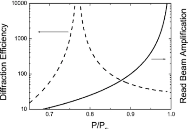
= R2exp共2gL / cos兲 and = ⌬gL / 共4 cos兲, whereis the angle of refraction of the read beam in the intracavity medium.Figure 1 shows the diffraction efficiency and the read beam amplification plotted as a function of the normalized pump power x = P / Pth, where Pth is the lasing threshold power. This threshold is character-ized by the equality 1 + R1R2
⬘
共gth兲 − 2冑
R1R2⬘
共gth兲 = 0(with gth proportional to the pump power Pth in the amplifying medium model considered in our analy-sis). Results of Fig. 1 were calculated for a Nd: YVO4 microlaser with R1= 0.95, R2= 1, L = 1 mm, g = xgth, and ⌬g = 0.6xgth. As expected, the read beam amplifi-cation diverges as P / Pth approaches unity. The dif-fraction efficiency also diverges but at a lower pump value, as can be inferred from Eq. (1). Figure 1 shows
208 OPTICS LETTERS / Vol. 32, No. 3 / February 1, 2007
that diffraction efficiencies larger than 100 may be expected over a large range of pump powers below the threshold power (0.72–0.85 Pth). This result is very encouraging for the development of practical de-vices with high fan-out values.
The principle of the proposed technique was tested using a conventional Nd: YVO4 microlaser. The ex-perimental setup is shown in Fig. 2. The 1 mm long intracavity gain medium is pumped below laser threshold by two interfering beams delivered by the same CW Ti:sapphire laser operating at 810 nm. Due to this modulated pumping achieved through 300m diameter beams, a small area intracavity gain grat-ing is written in the microlaser. This gratgrat-ing 共⌳ ⬇ 40m兲 is read at the Bragg angle (exterior inci-dence angle it⬇ 10 mrad) by a 200m diameter Nd:YAG laser beam whose frequency is resonant with the laser cavity. For this asymmetric cavity of fi-nesse F =
冑
4R1R2/ 共1 −冑
R1R2兲 ⬵ 100 (the front andback mirrors have reflection coefficients of 95% and 99%, respectively), there is only one significant dif-fracted beam counterpropagating the read beam and extracted by a beam splitter. Finally, the pump beams are chopped at 25 Hz with a useful opening of 1 / 400 to avoid undesirable thermal effects.
Measurement of the diffraction efficiency of the de-vice and transmitted read beam amplification were performed using this setup. Results are shown in Figs. 3(a) and 3(b), respectively. Neither amplifica-tion nor diffracamplifica-tion efficiency exhibits the asymptotic growth shown in Fig. 1. Actually, the number of over-lapping reflected beams in the intracavity grating is limited due to the combination of the small area of the grating and the oblique incidence of the read beam. The Fabry–Perot effective finesse, related to the number of reflected beams effectively interfering in the cavity, is therefore reduced as if the loss of the cavity were increased. This limitation was globally taken into account in the calculations by replacing R1 with a smaller value R1
⬘
= 0.90 in the resonant de-nominators of Eqs. (1) and (2). The corresponding curves shown in solid curves in Figs. 3(a) and 3(b) confirm the interpretation of the reduction by about a factor of 2 of the finesse of the Fabry–Perot cavity. Evidently this reduction has enormous consequences for the diffraction efficiency and must be avoided if a high fan-out value is required. This drawback, which is linked to the large thickness of the Fabry–Perot cavity, can be avoided by using a larger area gain grating or a thinner cavity, such as a vertical cavity surface-emitting laser, which is only few micrometers thick. Let us note, however, that even in our imper-fect experiment the diffraction efficiency reaches more than 20%. This is 5000 larger than the effi-ciency that would be obtained with the same gain modulation and no cavity. Moreover, diffraction effi-Fig. 1. Calculated diffraction efficiency of the intracavitygain grating and amplification of the read beam plotted as a function of the ratio between the real and threshold pumping powers.
Fig. 2. Experimental setup for writing and reading the gain grating, with an inset showing the sample in more detail.
Fig. 3. Measured diffraction efficiency of the intracavity gain grating (a) and amplification of the read beam (b) plot-ted as a function of the ratio between the real and thresh-old pump powers (squares). The solid curves correspond to calculations performed using Eqs. (1) and (2) and a reduced value of R1(see text).
ciencies larger than unity (nearly 2) were achieved with our setup using a higher modulation depth (50%–50% pump power distribution instead of 90%– 10%).
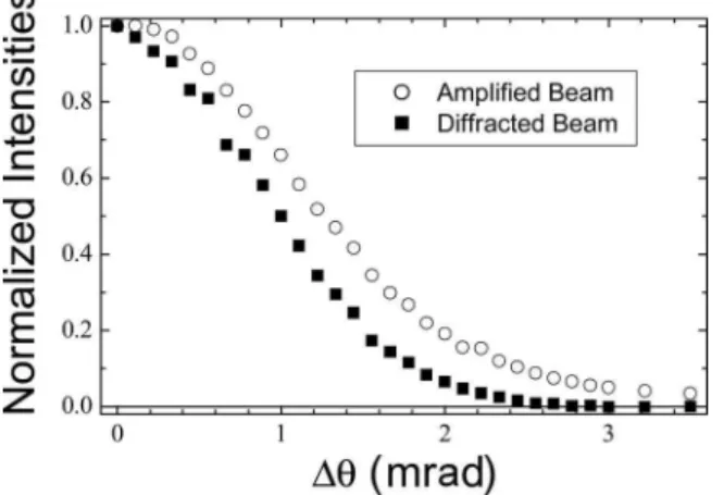
The resolution of the device was also tested by measuring its diffraction efficiency as a function of the detuning angle ⌬=−0 and comparing it with the Fabry–Perot selectivity defined from the cavity transmission. This is illustrated in Fig. 4, showing the normalized diffraction efficiency and the trans-mission of the device as a function of ⌬ (the Bragg and Fabry–Perot resonance angle i0= 13.3 mrad).
The normalized transmitted and reflected–diffracted intensities exhibit almost the same behavior, with a bandwidth (FWHM) of 2.7 and 2.1 mrad, respec-tively. Note that the resolution of this device is ten times better than that of the same 1 mm long gain grating with no cavity and be could even improved by using a larger area for the gain grating. This high
an-gular selectivity is evidently very important for po-tential applications to optical signal processing.
Intracavity gain gratings have demonstrated their potential for providing very high diffraction efficien-cies (larger than 100 for pump powers substantially below the lasing threshold). This enables the genera-tion of large fan-out values for practical optical signal processors. A huge enhancement of the diffraction ef-ficiency (a factor of 5000 compared with the same gain grating with no cavity) and a strong increase of the angular selectivity (about a factor of 10) were measured for an unoptimized device exhibiting a fi-nesse reduced compared with the ideal Fabry–Perot cavity. Much better results are expected with gain gratings of larger areas or with thinner Fabry–Perot cavities, as in the case of the vertical cavity surface-emitting lasers. All these advantages make intracav-ity gain gratings very attractive for optical signal processors when large fan-out values are needed.
I. Zaquine’s e-mail address is [email protected]. References
1. R. J. Collier, C. B. Burckhardt, and L. H. Lin, Optical
Holography (Academic, 1971).
2. Y. Ding, D. D. Nolte, M. R. Melloch, and A. M. Weiner, IEEE J. Sel. Top. Quantum Electron. 4, 332 (1988). 3. L. Menez, I. Zaquine, A. Maruani, and R. Frey, J. Opt.
Soc. Am. B 16, 1849 (1999).
4. L. Menez, I. Zaquine, A. Maruani, and R. Frey, Opt. Lett. 27, 479 (2002).
5. L. Menez, I. Zaquine, A. Maruani, and R. Frey, J. Opt. Soc. Am. B 19, 965 (2002).
6. L. Menez, I. Zaquine, A. Maruani, and R. Frey, Opt. Commun. 204, 267 (2002).
Fig. 4. Normalized intensities of the diffracted and trans-mitted beams plotted as a function of the detuning angle.