HAL Id: hal-02865278
https://hal.archives-ouvertes.fr/hal-02865278
Submitted on 9 Apr 2021
HAL is a multi-disciplinary open access archive for the deposit and dissemination of sci-entific research documents, whether they are pub-lished or not. The documents may come from teaching and research institutions in France or abroad, or from public or private research centers.
L’archive ouverte pluridisciplinaire HAL, est destinée au dépôt et à la diffusion de documents scientifiques de niveau recherche, publiés ou non, émanant des établissements d’enseignement et de recherche français ou étrangers, des laboratoires publics ou privés.
Adhesion of High Temperature Thermoplastic
Composites
Julien Avenet, Thomas Cender, Steven Le Corre, Jean-Luc Bailleul, Arthur
Levy
To cite this version:
Julien Avenet, Thomas Cender, Steven Le Corre, Jean-Luc Bailleul, Arthur Levy. Adhesion of
High Temperature Thermoplastic Composites. 23rd International Conference on Material Forming, ESAFORM 2020, May 2020, Cottbus (virtual), Germany. pp.925-932, �10.1016/j.promfg.2020.04.284�. �hal-02865278�
ScienceDirect
Procedia Manufacturing 00 (2019) 000–000 www.elsevier.com/locate/procedia
2351-9789 © 2020 The Authors. Published by Elsevier Ltd.
This is an open access article under the CC BY-NC-ND license https://creativecommons.org/licenses/by-nc-nd/4.0/) Peer-review under responsibility of the scientific committee of the 23rd International Conference on Material Forming.
23rd International Conference on Material Forming (ESAFORM 2020)
Adhesion of High Temperature Thermoplastic Composites
Julien Avenet
a,b, Thomas A. Cender
c, Steven Le Corre
a, Jean-Luc Bailleul
a,
Arthur Levy
a*
aUniversité de Nantes, CNRS, Laboratoire de Thermique et Energie de Nantes, LTeN, UMR6607, F-44000 Nantes, France bIRT Jules Verne, Chemin du Chaffault, 44340 Bouguenais
cSabanci University, Integrated Manufacturing Technologies Research and Application Center, Istanbul, Turkey
* Corresponding author. Tel.: +33 (0)2 40 68 31 22. E-mail address: arthur.levy@univ-nantes.fr
Abstract
Thermoplastic composites offer new manufacturing prospects, thanks to the ability to melt the matrix. Welding, tape placement, 3D printing, overmoulding, or even stamping involve adhesion of the thermoplastic polymer at high temperature. One of the leading mechanism that enable to build up strength of adherent over the substrate is called healing. It is classically described as the diffusion of the macromolecular chains across the interface that enable bridging. In continuous processes, such as some which are used in advanced manufacturing of aerospace structures, cycle times are very short. Thus, it is unclear how suitable these materials are for fast continuous processes – the limiting factor being the time required to gain adhesion. In order to model and predict such processes, a controlled welding bench was designed enabling very short welding times (~5 seconds). The mechanical adhesion between coupons was assessed by fracture of the welded interface via double cantilever beam fracture test. The welding kinetics were observed for the initial stages of healing with a behavior that should fit the 𝑡1/2 trend. From this, it was possible to compare the accuracy and repeatability of interface healing at short time scales to that of samples
which were closer to fully welded. Concurrently, the reptation of the polymer melt was assessed on a commercial rheometer, by computing relaxation time from the viscoelastic response. The correlation confirms that the mechanical quality is associated with the macromolecule diffusion. It was also observed that for high temperature thermoplastics, reticulation occurs, which inhibits molecular diffusion and increases the relaxation time. The major implication is that the preprocessing of the polymer will impact the subsequent adhesion step. For example, plates processed with an autoclave for a couple of hours would require a welding time an order of magnitude longer than the adhesion of a virgin prepreg in the tape placement process.
© 2020 The Authors. Published by Elsevier Ltd.
This is an open access article under the CC BY-NC-ND license https://creativecommons.org/licenses/by-nc-nd/4.0/) Peer-review under responsibility of the scientific committee of the 23rd International Conference on Material Forming.
Keywords: Thermoplastic ; Composite ; Welding ; Kinetic ; Experimental
1. Introduction
Thermoplastic matrix composites have gained popularity in the past decade, partly because they do not require lengthy curing cycle so that their processing can be faster. Moreover, the ability to melt the matrix gave rise to plenty of new forming processes amongst which thermo-forming, in-situ tape placement, 3D-printing, pultrusion or assembling processes such as ultrasonic or induction welding. In order to ensure
consolidation, all these processes require a heating step and an adhesion step. As a matter of fact, because these processes tend to be faster and faster (even continuous for some), the adhesion step is expected to be short.
Adhesion of thermoplastics, and more specifically thermoplastic composites, has been investigated for years. During the welding process, the composite pieces are brought together above the melting temperature of the polymer matrix.
2 Avenet Julien / Procedia Manufacturing 00 (2019) 000–000
Once intimate contact is achieved, the interface gradually disappears through a healing process and the mechanical strength at the interface develops to finally reach the one of the bulk. Wool and O’Connor [1] described the healing process as a succession of five steps: (1) surface rearrangement, (2) surface approach, (3) wetting, (4) diffusion and (5) randomization. During the first two stages, the assembly doesn’t have any mechanical strength as the initial interface still exists. The stage of wetting is described by the intimate contact between the two surfaces first introduced by Dara and Loss [2] to take into account the initial roughness of the surfaces and then simplified by Lee and Springer [3] which modeled the surface as a succession of identical rectangles that spread under temperature and pressure loading. Once the intimate contact is established, the macromolecules are free to move across the interface through the inter-diffusion process also called autohesion in the case of two similar composite pieces. This motion is usually described by de Gennes reptation theory [4] where a molecular chain is considered confined in a tube representing the topological constraints due to neighboring chains which prohibits lateral motions along the tube. Since the chain can only relax along the tube direction, the chain ends are free to move in any direction away from the tube such as the memory of the initial conformation is gradually lost up to a time 𝑡𝑟𝑒𝑝 called the reptation time where the chain has completely forgotten its initial configuration.
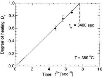
Wool [1] showed that when the reptation time approaches, diffusion and randomization stages are completed and that the maximum mechanical strength of the interface is reached. The degree of healing can thus be defined where tw is the welding time and tw,∞ is the reptation time and is related to the bond energy. It is classically used in the literature (see for instance [3], [5] and the Fig. 1).
𝐷ℎ= ( 𝑡𝑤 𝑡𝑤,∞)
1/4
(1)
At the microscopic scale, the authors [6]–[8] have different theories to explain the time dependency of mechanical properties recovery during the healing process but all of them agree that the fracture energy 𝐺𝐼𝐶 increases with the square root of time. 𝐷ℎ= ( 𝐺𝐼𝐶 𝐺𝐼𝐶,∞ ) 1/2 ∝ ( 𝑡𝑤 𝑡𝑤,∞ ) 1/4 (2) A proper characterization of the mechanical bond for short residence time of few seconds is very relevant to understand the fast processes used in the industry. To our knowledge, there is no adhesion characterization tests that were performed with such short residence times in the case of composite materials (see for instance Fig. 1 where the shortest time is about 400 seconds).
In order to characterize the mechanical quality of the bonded joints, two experimental benches were developed:
A short time welding bench under controlled conditions designed for fast heating and cooling
A double cantilever beam setup to characterize adhesion quality
The material and benches are presented in section 2, then the validation tests are shown in section 3 and preliminary industrial results are discussed in section 4.
Fig. 1. Healing degree in function of contact time for an AS4/PEEK composite isothermally welded at 380°C. Reported from [5]
2. Characterization Methods
This section describes the adhesion characterization procedure. Thermoplastic composite laminate coupons are welded together using the TACOMA bench (Fig. 3). The adhesion is then assessed using a double cantilever mechanical test (Fig. 5) following ASTM standard [9].
2.1. Materials
The material used in this study is an aeronautical grade Arkema PEKK 7002 thermoplastic reinforced with carbon fibres. Samples consisted of 12 plies of symmetric unidirectional fiber layup of [0°/90°]. Samples were hand laid-up into a flat plate. On one of the surface, a 50 µm thick film of pure PEKK polymer was applied which should ease the welding process. The layup was then consolidated in an autoclave at 380°C for 2 hours.
The matrix must be processed at temperatures above 350°C. At these temperatures it has been shown that degradation associated to chemical modification can occur [10]. This is likely influencing the welding time and will be discussed hereunder.
Fig. 2. Dimensions of the composite coupons. The grey circle represents the countersunk hole to insert the loading tabs
Before the welding experiments, the composites plates are cut into 125 x 25 mm samples (Fig. 2) using a Protomax waterjet cutting machine. A countersunk hole is machined in each sample 10 mm from one end, to insert a tab used for gripping the sample during fracture test. The coupons are then manually cleaned using acetone solvent and dried in a vacuum oven at 180°C for 20 hours while vacuum is applied by means of an air-vacuum pump in order to remove residual water and limit the laminate deconsolidation phenomena that would occur during the welding sequence.
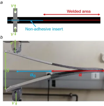
The composite side that will be in contact with the copper mold is covered with a polyimide tape to facilitate the removal of the welded coupons after the welding procedure. The initial crack along the mid-plane of the specimens was created by inserted a non-adhesive aluminum foil between the two samples 50 mm from the load application point such as the welded area was 65 mm long by 25 mm wide. Finally, the loading tabs are inserted into the samples prior to the welding experiment. They are engaged in a cavity machined inside the copper mold.
2.2. Experimental welding bench
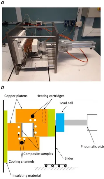
The welding bench was developed for welding composites substrates for a finite amount of time (down to a few seconds) and under constant isothermal conditions. The TACOMA (for Thermo-Adhesion by COnductive heating of composite MAterials) setup is described in Fig. 3.
It consists of a copper mold cavity comprising a static and a moving temperature controlled platens with an internal thermocouple near the sample surfaces (1 mm from the surface) and heated with heating cartridges. Additionally, two internal channels have been machined in each platen allowing a fast water cooling of the copper mold, thus quenching of the samples, and a stopped experiment.
The moving platen is attached in series to a pneumatic piston, a load cell and an insulating material to protect the load cell from the high temperatures and to limit heat losses. The 80 mm diameter pneumatic piston can apply a closing pressure up to 16 bars on the samples and the force is recorded with a 10 kN load cell. The dimensions of the mold are those of the samples such as the entire length of the samples is heated and pressed together. Two lateral copper plates (one on each side of the mold) are fasten on the mold to insulate the cavity from the ambient air and ensure a closed cavity. Finally, a slider is attached to the insulating material to minimize the friction between the platens and to bear the weight of the mold. In order to avoid holding issues of the samples, the setup was designed such as the samples are simply stacked on each platen, facing each other and resting on their thickness.
The experimental protocol to weld the two composite coupons is shown in Fig. 4. It can be divided into different steps: (1) heating of the copper block from room temperature
up to a temperature higher than the melting temperature of the material (at first the two samples are not in contact and the matrix-rich surfaces face each other), (2) homogenization of the temperature at the surface of the coupons, (3) once the temperature is reached and homogeneous inside the mold, the pressure is applied with the pneumatic piston to weld the samples during a finite contact time 𝑡𝑐, (4) fast cooling of the setup with water circulation to stop the welding process and (5) release of the pressure.
Fig. 3. (a) The experimental welding TACOMA setup and (b) schematic view of the setup
The pressure applied being important, the establishment of the intimate contact between the two composite samples is considered to be immediate and perfect. The limiting phenomena is therefore the inter-diffusion of macromolecules at the interface and the quality of the adhesion is solely the degree of healing 𝐷ℎ.
4 Avenet Julien / Procedia Manufacturing 00 (2019) 000–000
.
Fig. 4. Experimental welding procedure. The heating and temperature stabilization occur before the samples are put in contact.
2.3. Mechanical test
The mode I strain energy release rate is defined as the energy necessary to propagate a crack over a unit surface. For an elastic linear structure, the analysis of a double cantilever beam test is based on the change of compliance. The growth of a crack from 𝑎 to 𝑎 + ∆𝑎 induces a change in the compliance resulting in a loss of the stored energy. In this method, the compliance is determined by beam theory which consider that the adherents are clamped at the crack tip, thus neglecting the rotation of the adherents at the crack tip. It is then possible to determine the strain energy release rate from the Irwin-Kies equation [11]: 𝐺𝐼 = 𝑃2 2𝑏 𝜕𝐶 𝜕𝑎 (3)
where 𝑏 is the width of the sample, 𝑃 is the applied force, the compliance 𝐶 = 𝛿/𝑃 and the displacement 𝛿 at the loading point according to Euler-Bernoulli beam theory are respectively: 𝐶 = 8𝑎 3 𝐸𝑏ℎ3 𝛿 = 2𝑃𝑎3 3𝐸𝐼 (4)
where ℎ is the thickness, 𝐸 is the Young modulus and 𝐼 = 𝑏ℎ3/12 is the moment of inertia of the material.
The derivation of the equation 4 into the equation 3 leads to the most used expressions of the strain release energy rate in mode I [9], [12]: 𝐺𝐼 = 𝑃2𝑎2 𝑏𝐸𝐼 = 2𝑃2𝑎2 3𝐸𝐼 = 3𝑃𝛿 2𝑏𝑎 (5)
The mechanical strength of the welded interface is assessed using a double cantilever beam (DCB) fracture test following the ASTM standard [9]. The welded samples were mounted on
a 100 kN Zwick Roell tensile machine and homemade sample holders were used to fix the loading tabs onto the machine grips. Tests were performed in displacement control mode with a constant displacement rate 𝜈 of 1 mm.min-1 which correspond
to a quasi-static condition. The machined loading tabs prevents unwanted torque in the load (see Fig. 5). The load and displacement were continuously recorded during the test. The sample being welded only on a 65x25 mm² area, the elastic energy is also stored on the free arms of the part in the form of elastic bending energy.
Fig. 5. Double Cantilever Beam setup. The initial crack length 𝑎0 is
determined from the non-adhesive foil film insert
3. Validation of TACOMA design
3.1. Numerical model
A two-dimension numerical simulation was carried out in order to validate the design of the welding bench. It consisted in the modelling of heat transfer in the composite samples. Because of symmetry, the geometry used was the half of one sample as shown in Fig. 6.
The contact between the sample and the mold is modelled with a thermal contact resistance TCR. The thermal properties of the composite were measured experimentally and are thermo-dependent. The temperature of the copper mold is supposed uniform and is that measured by the control thermocouple.
Adhesion at the sample interface was modelled using the healing degree (equation 2) in its differential form:
𝑑(𝐷𝐻4)
𝑑𝑡 =
1
where 𝑡𝑤(𝑇) was solved from the literature [13]. Healing degree was integrated on each point of the interface to highlight the influence of the geometry.
Fig. 6. Geometry used in the modelling of the sample
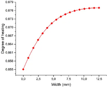
Healing degree was computed after 100 seconds welding time at 380°C on the interface and the result in Fig. 7 shows that the edge of the sample presents a healing degree lower than the center of about 2% because of edge effects induced by the proximity with the mold, i.e. a faster cooling.
Fig. 7. Profile of the healing degree along the interface computed numerically after 100 seconds of contact at 380°C.
3.2. Instrumentation
The homogeneity of temperature inside the TACOMA setup was characterized by placing a type K thermocouple between the two platens of the mold without any samples such that the thermocouple did not touch the mold. These tests were realized with and without the two lateral copper plates.
Samples instrumented with 80𝜇𝑚 type K thermocouples were also placed into the TACOMA setup. The thermocouples were embedded on the matrix-rich surface, at location given in Table. 1, in order to record the temperature at the interface between the two samples during the welding sequence. The sequence consisted in a heating up to 380°C, followed by 30 seconds contact. This test allowed the determination of the time needed to reach the targeted temperature at the interface. It also gave information on the edge effect. Indeed, samples are positioned against the copper mold. All sides of the sample except the one that will be welded are in contact with the
copper, they should therefore heat up and cool down faster than its centre. The degree of healing, being dependent on the temperature will probably be lower at the edges of the interface. The position of the thermocouples along the coupon’s surface is shown in Fig. 8.
Fig. 8. Positioning of the thermocouples along the sample's interface
Table. 1. Positions of the thermocouples along the sample’s interface.
Thermocouple T1 T2 T3 T4 Distance along x (mm) 92,5 92,5 92,5 92,5 Distance along y (mm) 2 5 8 12,5
3.3. Experimental validation
First, tests performed without any samples in the mold and with a thermocouple between the two platens are presented in Fig. 9. Without the lateral plates, the temperature inside the cavity never reaches the targeted temperature and is approximately 20°C below it. This is attributed to the natural air convection cooling down the interior of the cavity. On the contrary, with the lateral plates, the targeted temperature is reached with about 30 seconds delay. This validates the design of the lateral plates to confine the cavity from air convection.
Fig. 9. Evolution of the temperature between the two copper platens with and without the lateral plates
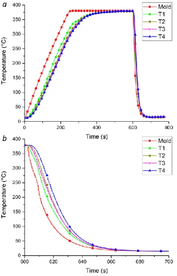
Secondly, the evolution of the temperature at the interface between the two samples at different positions during the welding sequence is shown in Fig. 10. From this we were able to determine the characteristic cooling rate both in the mold and at the sample interface (at the position T4) which are
6 Avenet Julien / Procedia Manufacturing 00 (2019) 000–000
respectively 20°C.s-1 and 12°C.s-1 allowing thereby the
quenching of the samples.
It also confirms that the temperature at the interface is homogeneous during the heating phase thanks to the lateral plates. They prevent natural air convection in the cavity and the temperature reaches the targeted one. In conclusion, in order to realize isothermal welding cycle, the pressure must be applied once the interface has reached the targeted temperature. For instance, for a welding temperature of 380°C, the pressure must be applied 300 seconds after the isothermal dwell because of temperature gradient in the sample thickness.
Finally, the instrumentation of the samples along the sample width validates that edge effects are present on the sides due to closer proximity with the mold. This results in a heating and cooling rate faster for the thermocouple T3 for instance. The edge effects are crucial during the cooling phase since they might induce a healing degree profile along the width of the samples: the center of the sample stays longer at high temperature before cooling starts, thus increasing the welding time of a few seconds. The degree of adhesion along the width could therefore present a parabolic profile.
Fig. 10. (a) Temperature versus time at different positions on the samples interface during the welding sequence; (b) close-up on the cooling phase
4. Adhesion results
Welding tests were performed using the TACOMA setup according to the experimental protocol introduced in section 2. The tests were performed at a temperature of 380°C at a closing pressure of about 3 bars and for different welding times: 1, 5, 20, 50, 80, 100, 125, 175, 200, 500 and 3600 seconds.
The double cantilever beam load-displacement curves are presented in Fig. 11. They present a saw-teeth behaviour characterized by sudden drops of the recorded force corresponding to unstable fractures. This is known as a stick-slip crack growth accompanied with high-speed propagation and arrest. On the contrary a stable behaviour is characterized by a continuous crack growth with the increase of displacement. This phenomenon has been observed by different authors. Harkous et al. [14] attributed this phenomena to very fast failure of the welded area and explained that for high resistance composite, the large amount of released energy causes a long propagation of the crack and consequently a complete break of the part. Sacchetti [15] also observed this behaviour for unidirectional Carbon/PEEK laminates and explained that it was due to a non-uniformity of the matrix rich layer at the surface of their samples resulting in a non-uniform interlaminar fracture toughness along the crack path.
Fig. 11. Load-displacement curves for the fracture double cantilever beam test. Crack propagation is unstable.
Due to unstable crack propagation and difficulties in measuring the crack length during the double cantilever beam test, critical strain release energy rates 𝐺𝐼𝐶 are calculated at the crack initiation point corresponding to the first peak in the load-displacement curve. At this point, the crack length is known and corresponds to the length 𝑎0 of the non-adhesive aluminum insert. 𝐺𝐼𝐶,𝑖𝑛𝑖 values are calculated using equation (5).
Temperature evolution at the interface of the samples presented in the latter section show that the center of the interface stays a little bit longer at 380°C than the mold. Therefore, the welding time defined in the sequence needs to be corrected to account for the adhesion that might develops during the quenching phase. A corrected time 𝑡𝑐𝑜𝑟𝑟 is then
introduced and used as the welding time. Healing degree ( 𝐺𝐼𝐶
𝐺𝐼𝐶,∞)
1/2
is then plotted versus the fourth root of corrected contact time in Fig. 12.
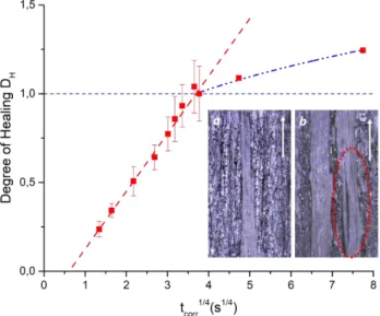
Fig. 12. Evolution of healing degree versus corrected welding time. Images of the fractured interfaces welded for (a) 100 seconds and (b) 200 seconds. Evidence of a fibre breakage and differential flow of the fibres is highlighted
in red. The white arrows refer to the opening direction.
Results shows that the healing degree follows the classical 𝑡1/4 dependency. Discrepancies at long welding times (i.e. from 125 seconds) could be due to a competition between pure healing and fiber bridging thus inducing sometimes high values of 𝐺𝐼𝐶. The welding test performed for a contact time of 200 seconds was then used as the maximum value of 𝐺𝐼𝐶 which is equal to 𝐺𝐼𝐶,∞= 3.125 ± 0.740 𝑘𝐽. 𝑚−2. Considering that the maximum mechanical resistance is reached at long welding time, it is possible to extrapolate the first part of the curve. The point where it crosses the line at 𝐷𝐻= 1 is the time necessary to fully weld the composite parts. In our case this time is about 186 seconds. Extrapolation of the line at the very short times show that 𝐷𝐻= 0 is reached for a certain welding time which is unlikely to happen.
The curve can thus be divided into three parts:
(1) The delay at the bottom of the curve could be associated to the establishment of intimate contact between the surfaces: adhesion might start between the first asperities that come in contact.
(2) The 𝑡1/4 part would purely be associated to the diffusion process of the macromolecules at the interface: this is the healing stage.
(3) The last part is characterized by a second inflection where the fracture energy still increases with time inducing a healing degree higher than one. This artifact could be attributed to other adhesion phenomena such as fibre bridging combined with differential flow and segregation of the polymer matrix. They are therefore not associated to pure healing process.
High performance composites are manufactured in autoclave at temperatures above 350°C. At these temperatures
it has been shown that degradation associated to chemical modification can occur [13], thus increasing the relaxation time. For example, the relaxation time for virgin prepreg in the tape placement process is around 1 second. But, in our case, the laminates have been consolidated for 2 hours in an autoclave at 380°C, the identified welding time is consequently increased. This justifies the long obtained values of a hundred seconds. 5. Conclusion
In this work, adhesion of thermoplastic composites is investigated. The goal is to characterize adhesion for conditions close to the industrial process especially short residence time. Under such conditions, the intimate contact phenomenon that may limit adhesion when rough surfaces are welded with low closing pressure is achieved quickly. Thus, the limiting phenomenon in adhesion build-up is healing of the interface.
To characterize this adhesion kinetics, a new controlled experimental welding bench was designed which enables quenching of double cantilever beam samples after short welding durations. Welding tests over a large range of times allowed the identification of the classical adhesion kinetics for short welding times. Secondly, fiber bridging was observed for long welding times as well as segregation which induce higher values of fracture energies and overestimate the healing degree. It was also hypothesized that the curve could present an inflection at very short welding times that might correspond to the establishment of intimate contact. Finally, the welding times evolved due to thermal history of the samples.
In perspectives, welding tests performed at lower temperatures will be conducted and in order to scale up this theory to the realistic manufacturing processing thermal cycles, it will be extended to non-isothermal temperature history [5]. Acknowledgements
The authors would like to thank Jérôme Delmas for the help on the designing and machining of the TACOMA setup. The authors would like to acknowledge the funding of the PERFORM project managed by the IRT Jules Verne (French Institute for Research and Technology in Advanced Manufacturing Technologies for Composite, Metallic and Hybrid Structures) that made this work possible. The authors wish to associate the industrial partners of the PERFORM project: Airbus, Stelia Aerospace, Faurecia, Naval Group and Daher.
References
[1] R. P. Wool and K. M. O’Connor, “A theory of crack healing in polymers,” J. Appl. Phys., vol. 52, pp. 5953–5963, 1981. [2] P. H. Dara and A. C. Loos, “Thermoplastic Matrix Composite
Processing Model,” 1985.
[3] Woo Il Lee and G. S. Springer, “A Model of the Manufacturing Process of Thermoplastic Matrix Composites,” J. Compos. Mater., vol. 21, no. 11, pp. 1017–1055, 1987.
[4] P. G. De Gennes, “Reptation of a polymer chain in the presence of fixed obstacles,” J. Chem. Phys., vol. 55, pp. 571–579, 1971.
8 Avenet Julien / Procedia Manufacturing 00 (2019) 000–000 [5] F. Yang and R. Pitchumani, “Healing of thermoplastic polymers at
an interface under nonisothermal conditions,” Macromolecules, vol. 35, pp. 3213–3224, 2002.
[6] S. Prager and M. Tirrell, “The healing process at polymer – polymer interfaces The healing process at polymer-polymer interfaces,” J. Chem. Phys., vol. 75, no. 10, pp. 5194–5198, 1981. [7] Y. H. Kim and R. P. Wool, “A theory of healing at a
polymer-polymer interface,” Macromolecules, vol. 16, pp. 1115–1120, 1983. [8] K. Jud, H. H. Kausch, and J. G. Williams, “Fracture Mechanics
Studies of Crack Healing and Welding of Polymers,” J. Mater. Sci., vol. 16, pp. 204–210, 1981.
[9] ASTM International, “D5528 - Standard Test Method for Mode I Interlaminar Fracture Toughness of Unidirectional Fiber-Reinforced Polymer Matrix Composites,” 2013.
[10] T. Choupin, B. Fayolle, G. Régnier, C. Paris, J. Cinquin, and B. Brulé, “Macromolecular Modifications of Poly
(EtherKetoneKetone) (PEKK) Copolymer at the Melting State,” Polym. Degrad. Stab., vol. 155, pp. 103–110, 2018.
[11] G. R. Irwin and J. A. Kies, “Critical Energy Rate Anaysis of Fracture Strength,” Weld. J. Res. Suppl., vol. 33, pp. 193–198, 1954.
[12] V. Tamuzs, S. Tarasovs, and U. Vilks, “Delamination properties of translaminar-reinforced composites,” Compos. Sci. Technol., vol. 63, no. 10, pp. 1423–1431, 2003.
[13] T. Cender, A. Levy, and S. Le Corre, “Conitnuous Fusion Bonding of High Temperatures Thermoplastic Composite Structures with Volumetric Heating,” in ICMAC Conference, 2018.
[14] A. Harkous, T. Jurkowski, J. L. Bailleul, and S. Le Corre, “Influence of the temperature on the composites’ fusion bonding quality,” AIP Conf. Proc., vol. 1896, no. April, 2017.
[15] F. Sacchetti, W. J. B. Grouve, L. L. Warnet, and I. Fernandez, “Effect of Resin-rich Bond Line Thickness and Fibre Migration on the Toughness of Unidirectional Carbon / PEEK Joints,” Compos. Part A, vol. 109, no. July 2017, pp. 197–206, 2018.