HAL Id: in2p3-01201552
http://hal.in2p3.fr/in2p3-01201552
Submitted on 17 Sep 2015HAL is a multi-disciplinary open access
archive for the deposit and dissemination of sci-entific research documents, whether they are pub-lished or not. The documents may come from teaching and research institutions in France or abroad, or from public or private research centers.
L’archive ouverte pluridisciplinaire HAL, est destinée au dépôt et à la diffusion de documents scientifiques de niveau recherche, publiés ou non, émanant des établissements d’enseignement et de recherche français ou étrangers, des laboratoires publics ou privés.
Electronic structures and geometries of the XF3 (X =
Cl, Br, I, At) fluorides
Dumitru-Claudiu Sergentu, Mohamed Amaouch, Julien Pilmé, Nicolas
Galland, Rémi Maurice
To cite this version:
Dumitru-Claudiu Sergentu, Mohamed Amaouch, Julien Pilmé, Nicolas Galland, Rémi Maurice. Elec-tronic structures and geometries of the XF3 (X = Cl, Br, I, At) fluorides. Journal of Chemical Physics, American Institute of Physics, 2015, 143, pp.114306. �10.1063/1.4930609�. �in2p3-01201552�
Electronic structures and geometries of the XF3 (X = Cl, Br, I, At) fluorides
Dumitru-Claudiu Sergentu,1, 2 Mohamed Amaouch,3, 4 Julien Pilm´e,3, 4 Nicolas Galland,2, a)
and R´emi Maurice1, b)
1)SUBATECH, UMR CNRS 6457, IN2P3/EMN Nantes/Universit´e de Nantes,
4 Rue A. Kastler, BP 20722, 44307 Nantes Cedex 3, France
2)CEISAM, UMR CNRS 6230, Universit´e de Nantes, 2 Rue de la Houssini`ere,
BP 92208, 44322 Nantes Cedex 3, France
3)Sorbonne Universit´es, UPMC Univ Paris 06, UMR 7616,
Laboratoire de Chimie Th´eorique, Case Courier 137, 4 place Jussieu,
75252 Paris Cedex 05, France
4)CNRS, UMR 7616, Laboratoire de Chimie Th´eorique,
Case Courier 137, 4 place Jussieu, 75252 Paris Cedex 05, France
(Dated: 28 August 2015)
The potential energy surfaces of the group 17 XF3 (X = Cl, Br, I, At) fluorides
have been investigated for the first time with multiconfigurational wave function
theory approaches. In agreement with experiment, bent T-shaped C2v structures are
computed for ClF3, BrF3 and IF3, while we predict that an average D3h structure
would be experimentally observed for AtF3. Electron correlation and scalar relativistic
effects strongly reduce the energy difference between the D3h geometry and the C2v
one, along the XF3 series, and in the X = At case, spin-orbit coupling also slightly
reduces this energy difference. AtF3 is a borderline system where the D3h structure
becomes a minimum, i.e. the pseudo Jahn-Teller effect is inhibited since electron correlation and scalar-relativistic effects create small energy barriers leading to the
global C2v minima, although both types of effects interfere.
a)Electronic address: nicolas.galland@univ-nantes.fr b)Electronic address: remi.maurice@subatech.in2p3.fr
I. INTRODUCTION
During the past decades, several computational works concerning the geometries of group
17 element XF3 fluorides (where X = Cl, Br, I, At, or even element 117), were reported.1–9
These systems are not only of fundamental interest since they can be the subject of industrial
applications. ClF3 is a strong oxidizer, used as a fluorinating agent, and involved nowadays
in the synthesis of uranium hexafluoride. BrF3 is only used as a fluorinating agent in organic
synthesis, while no application involving IF3 is yet known. Several attempts to synthesize
astatine fluorides turned out to be unsuccessful.10 The determination of the geometries of
these known and hypothetical XF3 systems is a task of fundamental interest in theoretical
chemistry. The valence shell electron pair repulsion model11,12 supports bent T-shaped C
2v
geometries (see Figure 1). Experimentally, such geometries were evidenced for ClF313,14 and
BrF315 in the gas phase, and also in the condensed state of IF3.16 Regarding the (117)F3
system, a planar D3h structure is predicted from computations,4,5,9 while AtF3 is a borderline
system where the T-shaped C2v and the D3h structures are almost isoenergetic.2,4,5,9 For the
XF3 (X = Cl, Br, I) systems, such a D3h structure is unstable due to the pseudo Jahn-Teller
effect (PJTE).17 The detailed description of the PJTE in these cases was first given by
Schwerdtfeger.2 In the AtF
3 case, the D3h situation corresponds to a local minimum,5,9
meaning that the PJTE is in this case inhibited by other electronic factors.
α 120°
re
req
rax
FIG. 1. Ball and stick representations of T-shaped C2v (left) and planar D3h (right) XF3 geometries. [Color code: maroon (X = Cl, Br, I, At), light blue (F)].
From a quantum mechanical perspective, non-relativistic (NR), scalar-relativistic (SR)
and spin-orbit coupling (SOC) calculations have been performed1,2,4,5,9 in order to determine
critical points on the ground state potential energy surfaces (PESs) of these XF3 systems,
as well as for determining energy differences between them, especially the one between the
critical points of the PES are still not reported or discussed. Regarding most of the transition states (TSs), their nature (i.e. their connectivities with minima of the PESs) was generally
not rigorously established. The most emblematic case is the AtF3 system where important
aspects are still a matter of debate in the literature. For instance, very recently Yang and
Wang9 stated that the T-shaped C
2v structure is the only candidate to be observed through
experiments. But one may think at first glance that their reasoning is a bit odd. Strong issues
are related to the existence of the D3h structure as a true minimum, e.g. about the effects
that inhibit the PJTE in this case. Different factors such as electron correlation, SR effects
and SOC are able to significantly affect ∆ED3h−C2v. It is well known that numerous properties
of At species are highly sensitive to SOC.18–23 Thus, the most recent investigations5,9 had
focused on the relationship between SOC and the PJTE at the D3h structure. However, no
definite statement has yet been made.9 Indeed, one needs to consider the different factors
not solely at the D3h structure, but also how they affect the PES in its close vicinity in order
to reach a relevant conclusion. Furthermore, all previous theoretical studies made use of single-determinental methods while the reliability of such approaches has not been verified in difficult cases like AtF3.
In this article, we aim at resolving the above-mentioned points through multiconfigurational wave function theory (WFT) calculations, via a contracted spin-orbit configuration interaction approach, and additional spin-orbit density functional theory (SO-DFT) calculations. Note that the two-step spin-orbit WFT approach have been already validated in iodine and astatine
containing systems.24,25 Since this work also deals with the ClF
3 and BrF3 systems, we will
start by validating the choice of the exchange-correlation functionals used to explore the PESs of interest. The obtained geometries of the critical points will be used for subsequent multiconfigurational WFT calculations, aiming at studying the dependence of the results on the degrees of freedom associated to this methodology. Finally, based on multiconfigurational calculations, we will discuss the role of electron correlation, scalar relativistic effects, and
SOC along the XF3 series in order to clarify and complement the conclusions of previous
II. METHODOLOGY
A. DFT calculations
The critical points of the PESs corresponding to the ground state of the XF3 (X = Cl–At)
systems were optimized using NR-DFT (X = Cl), SR-DFT and SO-DFT (X = Br–At) approaches. NR- and SR-DFT calculations have been performed using the GAUSSIAN09
program package,26 while all the SO-DFT ones were carried out with the NWChem program
package.27 Vibrational harmonic frequencies have been determined to establish the nature of
the different critical points. Afterwards, the connectivities between TSs and minima were established through the computation of intrinsic reaction coordinate (IRC) paths at NR or SR levels.
The M06-2X28 and PBE029,30 hybrid exchange-correlation functionals were considered,
since these two functionals showed good performance on the XF3 (X = I–117) fluorides.9
In order to further discuss the role of the fraction of “exact” exchange on the performance of DFT functionals on these systems, this fraction has been also varied in a hybrid PBE functional, PBEh(x), where x denotes the percentage of exact exchange.
In the SR-DFT and SO-DFT calculations, energy-consistent small-core ECPnMDF
pseudopotentials31,32 were used to mimic the effects of the n = 60 core electrons of At,
n = 28 core electrons of I, and n = 10 core electrons of Br. Note that in the SO-DFT calculations, the pseudopotentials account for both scalar relativistic effects and SOC. For describing the explicitly treated electrons (25 in the neutral atoms), the aug-cc-pVTZ-PP-2c
basis sets33 were used for the At and I atoms, while the aug-cc-pVTZ-PP one31 was used for
Br. All-electron aug-cc-pVTZ basis sets34,35 were used for the Cl and F atoms.
B. WFT calculations
All the WFT calculations were performed with the ORCA program package.36 Regarding
the ClF3 and BrF3 systems, reference values for ∆ED3h−C2v were obtained with the CCSD(T)
method by means of geometry optimizations. For ClF3, the relativistic effects were neglected
and TZVP basis sets were used.37 For BrF
3, scalar relativistic effects were taken into account
via the use of the Douglas-Kroll-Hess Hamiltonian38–40 and accordingly, the segmented
Two-step WFT calculations were then performed. In the first step, a set of spin-orbit free (SOF) states is computed at a multiconfigurational level, here using the state-averaged
complete active space self-consistent field (SA-CASSCF) approach.42,43 The calculations were
performed on the previously optimized (SO-)DFT structures. In the second step, the spin components of the SOF states are used to build a state-interaction matrix, consisting of correlated energies on the diagonal, and off-diagonal SOC matrix elements computed within
a mean-field approximation.44,45 An important degree of freedom concerns the method used
to compute the correlated energies, which can be SA-CASSCF or the n-electron valence
state second-order perturbation theory (NEVPT2) method.46 The latter accounts for more
dynamic correlation and usually does not suffer from the occurrence of intruder states. The
SARC-TZVP-DKH basis sets41,47 were used for all atoms in these calculations, and scalar
relativistic effects were accounted for via the Douglas-Kroll-Hess Hamiltonian.38–40
Regarding the CASSCF calculations, two active spaces have been considered: (i) a minimal one (in view of SOC calculations) comprising only 2 electrons and the np orbitals of the central atom, leading to CASSCF(2/3) calculations, and (ii) a larger one comprising 20 electrons and the np and 2p orbitals of the central and F atoms, leading to CASSCF(20/12) calculations. In the SA-CASSCF(2/3) calculations, two state-averaging schemes have been
considered: the full one consisting of the MSmax components of the 6 singlet (S) and 3 triplet
(T) spin states (6S3T), and a subset of it, containing the ground SOF state plus all the essentially singly-excited states, i.e. 3S and 2T states (3S2T). For the SA-CASSCF(20/12) calculations, only one averaging scheme has been considered, namely 21S20T. Note that
this averaging-scheme fulfills the following conditions for all the studied XF3 systems, (i)
it does not artificially break the symmetry in the D3h structures, (ii) it includes all the
essentially singly excited states, and (iii) the enlargement of the state-averaging space and of the corresponding state-interaction space hardly affect the computed SOC ground state energy stabilizations.
Furthermore, specific Hartree-Fock (HF) and NEVPT2 calculations were performed at NR and SR levels in order to highlight the role of scalar relativistic effects, electron correlation and SOC on the stability of some structures. These calculations made use of fully uncontracted SARC-TZVP-DKH basis sets in order to avoid any bias introduced by the contraction scheme.
III. RESULTS AND DISCUSSION
A. DFT study
We start our analysis by looking at the performance of the M06-2X and PBE0 functionals
in determining the geometries of the D3h and T-shaped C2v structures, as well as the
energy difference between them (∆ED3h−C2v). With both functionals, the T-shaped C
2v
structures are minima of the PESs for all the studied XF3 systems. The D3h structure is a
second-order saddle point in the X = Cl–I cases, with one doubly-degenerate e0 imaginary
frequency. In contrast, the D3h structure is found to be a (weak) local minimum in the
AtF3 case. These results are compared to experimental data, when available, as well as
to (SO-)CCSD(T) reference calculations (see Table I). Since the CCSD(T) equilibrium
geometries are in very good agreement with the experimental ones for the ClF3 and BrF3
T-shaped C2v structures, both sets of results can be alternatively used to assess the quality
of the (SO-)DFT results. Table I reveals that both the PBE0 and M06-2X functionals lead to geometries in very good agreement with the (SO-)CCSD(T) ones, and when available, with the experimental data. For instance, the obtained deviation with the PBE0 functional regarding the equilibrium bond lengths with respect to the (SO-)CCSD(T) ones is less than 2% for each studied system. However, important discrepancies with the CCSD(T) results
appear in some cases for ∆ED3h−C2v. While (SO-)PBE0 gives reasonable energy differences
compared to (SO-)CCSD(T) for the whole XF3 series, the (SO-)M06-2X results deviate
more and more from X = At to X = Cl. For ClF3, the ∆ED3h−C2v value computed with the
M06-2X functional is too large by ∼30 kJ mol−1 with respect to the CCSD(T) value. One
can conclude that the PBE0 functional is overall more adequate than the M06-2X one for
studying PESs in the XF3 (X = Cl–At) series.
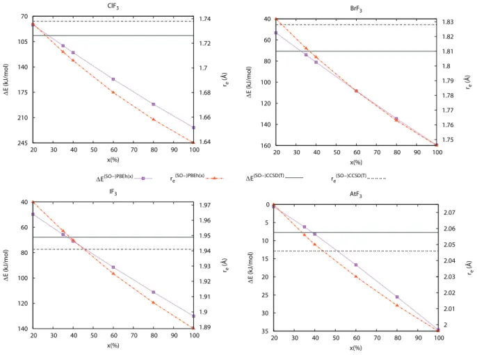
In order to highlight the role of the fraction x of exact exchange in hybrid functionals,
we monitored the re bond length (D3h case) and ∆ED3h−C2v while varying x in PBEh(x)
functional, from 20 to 100 % (see Figure 2). Using B3LYP as the reference functional, Yang
and Wang9 had performed a similar study but restricted to the case of AtF
3. We find similar
trends in the whole XF3 series, i.e. both re and ∆ED3h−C2v diminish with the fraction of
exact exchange. When comparing to the (SO-)CCSD(T) results, we find, for instance in
TABLE I. Geometrical parameters of the D3h and T-shaped C2v structures computed at various levels of theory, and associated energy differences.
System Method D3h T-shaped C2v ∆ED3h−C2v (kJ mol−1) re(˚A) req(˚A) rax(˚A) α(◦) ClF3 NR-M06-2X 1.713 1.592 1.696 86.6 128.4 NR-PBE0 1.728 1.603 1.706 87.4 91.5 SR-CCSD(T) 1.738 1.605 1.703 87.1 96.7 Expt.13 - 1.598 1.698 87.5 -BrF3 SO-M06-2X 1.815 1.715 1.802 85.4 93.2 SO-PBE0 1.825 1.725 1.812 86.4 60.2 SR-CCSD(T) 1.828 1.725 1.811 86.0 70.7 Expt.15 - 1.721 1.810 86.2 -IF3 SO-M06-2X 1.956 1.866 1.940 83.0 79.2 SO-PBE0 1.965 1.878 1.950 83.8 55.0 SO-CCSD(T)9 1.941 1.853 1.926 83.3 67.8 AtF3 SO-M06-2X 2.059 1.993 2.059 89.1 10.3 SO-PBE0 2.068 2.012 2.068 91.0 2.4 SO-CCSD(T)9 2.046 1.987 2.046 89.1 7.7
respect to the ∼55 % obtained in Ref. 9 . This discrepancy is due to the use of another reference functional. Therefore, the good performance of hybrid functionals for computing
geometries and energy differences in the XF3 series is not only related to the fraction of
exact exchange since different functionals with very different fractions of exact exchange can lead to a similar accuracy. From Figure 2, one would conclude that the recommended
fractions of exact exchange would range from 20–30 % (ClF3 case) to 35–45 % (IF3 case)
for PBEh(x). Overall, one could recommend to use the PBEh(35) functional. However, not much improvement would be reached compared to the standard PBE0 functional (x=25), which has therefore been used in the rest of this work.
We now question the nature of the Y-shaped C2vTSs on the PESs of the XF3 systems, that
were previously reported by Yang and Wang.9 Table II displays the computed geometrical
245 210 175 140 105 70 20 30 40 50 60 70 80 90 100 1.64 1.66 1.68 1.7 1.72 1.74 ∆ E (kJ/mol ) re (Å ) x(%) ClF3 160 140 120 100 80 60 40 20 30 40 50 60 70 80 90 100 1.75 1.76 1.77 1.78 1.79 1.8 1.81 1.82 1.83 ∆ E (kJ/mol ) re (Å ) x(%) BrF3 140 120 100 80 60 40 20 30 40 50 60 70 80 90 100 1.89 1.9 1.91 1.92 1.93 1.94 1.95 1.96 1.97 ∆ E (kJ/mol ) re (Å ) x(%) IF3 35 30 25 20 15 10 5 0 20 30 40 50 60 70 80 90 100 2 2.01 2.02 2.03 2.04 2.05 2.06 2.07 ∆ E (kJ/mol ) re (Å ) x(%) AtF3
∆E(SO−)PBEh(x) re(SO−)PBEh(x) ∆E(SO−)CCSD(T) re(SO−)CCSD(T)
FIG. 2. Evolution of the energy differences between the C2v and D3h structures (∆ED3h−C2v) and of the D3h bond lengths (re) as a function of the fraction of exact exchange (x) introduced in the PBEh(x) functional.
with respect to the T-shaped C2v global minima. The comparison with the D3h structure
shows for the ClF3, BrF3 and IF3 cases that the rax bond lengths are smaller than re, the req
bond lengths are larger than re and the α bond angles are larger than 120◦. Such Y-shaped
TSs are expected to be involved in the pseudo-rotations between two equivalent T-shaped
C2v global minima, as suggested in the ClF31 and IF39 cases. We confirm this hypothesis
through IRC calculations as displayed in Figure 3. Note that going from the D3h to the
T-shaped C2v structure via a Y-shaped C2v TS does not involve a drastic change in the
electronic configuration.
Regarding the AtF3 system, a Y-shaped C2v TS also exists but its structure exhibits an
0 20 40 60 80 −10 −5 0 5 10 E (kJ/mol ) IRC coordinate ClF3 BrF3 IF3 0 2 4 6 8 10 12 −6 −5 −4 −3 −2 −1 0 1 E (kJ/mol ) IRC coordinate AtF3
FIG. 3. Energies along the IRC paths starting from Y-shaped C2v TSs, computed at NR- or SR-PBE0 levels (the T-shaped C2v energies are chosen as the zeroes of energy).
TABLE II. Geometrical parameters of the Y-shaped C2v TSs computed at various levels of theory, and associated energy differences ∆ETS−C2v.
System Method req(˚A) rax(˚A) α(◦) ∆ETS−C2v (kJ mol−1)
ClF3 NR-M06-2X 1.770 1.676 130.9 121.5 NR-PBE0 1.762 1.703 128.7 89.3 BrF3 SO-M06-2X 1.848 1.793 128.7 90.8 SO-PBE0 1.843 1.814 125.6 59.9 IF3 SO-M06-2X 1.981 1.940 127.8 77.9 SO-PBE0 1.978 1.958 124.4 54.9 SO-CCSD(T)9 1.960 1.930 126.4 67.3 AtF3 SO-M06-2X 2.053 2.060 117.8 11.1 SO-PBE0 2.047 2.075 108.7 3.1 SO-CCSD(T)9 2.039 2.049 116.0 7.8
smaller than re. Furthermore, this TS is (slightly) higher in energy than the D3h structure,
in contrast to what is observed for ClF3, BrF3 and IF3. Hence, this TS exhibits a different
nature and it was suggested to connect T-shaped C2v and D3h minima by Yang and Wang.9
Note that differences appear between the results presented in Table II and the energy profiles
0 50 100 150 200 −15 −10 −5 0 5 10 15 E (k J/mol ) IRC coordinate AtF3
r
outr
outr
inFIG. 4. CsTS structure of AtF3 with displacement vectors traced for the imaginary frequency (left) and energy along the IRC path starting from the Cs TS and computed at SR-PBE0 level (right). The energy of the T-shaped C2v minimum is chosen as the zero of energy.
SOC notably stabilizes the Y-shaped C2v and the D3h structures compared to the T-shaped
one.
In the literature, the potential existence of TSs connecting T-shaped C2v minima in AtF3
was not considered. At SR levels, we have identified a Cs TS with an out-of-plane distorted
geometry (see Figure 4). This Cs TS actually connects two T-shaped C2v minima, as shown
by the IRC profile (see Figure 4). SOC significantly stabilizes the TS and modifies its
geometrical parameters close to a C3v structure at the SO-M06-2X level, and leads to the
practical impossibility of converging on a Cs structure at the SO-PBE0 level. The optimized
SR-DFT and SO-DFT geometrical parameters of the Cs TS are compiled in Table III.
In close connection with the Cs TS structure, a second-order saddle point belonging to the
C3v symmetry point group was evidenced. The doubly-degenerate imaginary frequencies are
57i and 67i cm−1 at the SO-M06-2X and SO-PBE0 levels, respectively. Note that in the limit
of a doubly-degenerate zero-frequency normal mode, this C3v structure would correspond
to a “monkey”48,49 saddle point associated with the trifurcation toward the three possible
Cs TS structures. Such situation was for instance suggested in (tetracoordinated) AX4
it would violate some rules.51,52 The fact that we failed to optimize the C
s TS structure at
the SO-PBE0 level could be related to the near degeneracy with the C3v structure. The near
degeneracy between the Cs and C3v geometries is also an indication for the existence of an
effective “monkey” C3v saddle point in AtF3, even if no definitive conclusion can actually be
given on this point.
TABLE III. AtF3 geometrical parameters of the Cs TS computed at SO-DFT and SR-DFT (in parenthesis) levels of theory, corresponding imaginary harmonic frequency, and associated energy difference ∆ETS−C2v.
Method rin(˚A) rout(˚A) ν1(cm−1) ∆ETS−C2v (kJ mol−1) SO-M06-2X 2.061 (1.957) 2.062 (2.063) 106i (314i) 156.4 (256.0)
SO-PBE0 (1.969) (2.078) (308i) (242.8)
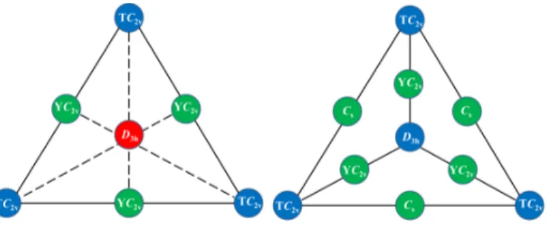
Schematic representations of the connectivity maps for the ground state PESs of the
studied XF3 systems are shown in Figure 5. For X = Cl–I, the D3h structure is a second-order
saddle point and three equivalent T-shaped C2v global minima are connected via Y-shaped
C2v TSs. For AtF3, the D3h structure is a “weak” local minimum, while three equivalent
T-shaped C2v structures correspond to global minima of the PES. Between the D3h and each
T-shaped C2v structure, there is a very small energy barrier associated to a Y-shaped C2v
TS. At SR levels, each pair of T-shaped C2v minima are connected via a Cs TS leading to
a large energy barrier. When SOC is included in M06-2X calculations, the Cs structure is
brought very close in terms of geometry and energy to a more symmetric C3v one. Note
that dissociation energies corresponding to the formation of either XF + F2 or XF2 + F are
reported in Table SI.53 All the critical points reported in Figure 5 are found lower in energy
than the lowest dissociation limit for each XF3 system.
Finally, we find that the inclusion of entropic and thermal contributions significantly
reduces the difference in stability between the D3h and C2v minima. At T = 298 K and
P = 1 atm, the difference in free energy is 3.6 and 0.3 kJ mol−1 at the SO-M06-2X and
SO-PBE0 levels, respectively. Given the accuracy of the used approaches, it becomes
impossible to conclude on the nature of the AtF3 most stable structure (C2v or D3h).
However, since the free energy difference between these structures and the associated energy barriers are so small, it would be impossible to experimentally distinguish between these two
structures, and therefore, an average D3h geometry would be seen in the experiments, if they
were possible.
FIG. 5. Schemes of the connectivity maps between the important critical points of the PESs of the XF3 systems, X = Cl–I (left), X = At (right). [Color code: blue is used for minima, green for TSs and red for second-order saddle points.]
B. WFT study
The dependence of the results with respect to computational degrees of freedom was first assessed by means of single-point calculations on previously obtained DFT geometries. Since in two-step WFT calculations the SOC is introduced a posteriori, it is straightforward to
distinguish SOF and SOC contributions to ∆ED3h−C2v. In Tables SII–SIV and IV, SOC
stabilizations of the T-shaped C2v and the D3h structures, namely ESOCC2v and E
D3h
SOC are
reported. It is therefore possible to quantify SOC effects (∆ED3h−C2v
SOC ) on ∆ED3h
−C2v. Tables SII and SIII collect energy parameters computed at the NEVPT2(2/3) and NEVPT2(2/3)+SOC levels of theory, with 6S3T and 3S2T averaging schemes. As expected,
both schemes lead to quite similar results. At these levels, ∆ED3h−C2v is rather constant in
the series from X = Cl to X = I, while it is much smaller in the AtF3 case. According to
the reference CCSD(T) results, a significant decrease of ∆ED3h−C2v is expected from ClF
3 to
BrF3, which is not reproduced at the considered NEVPT2(2/3) levels. This fact is probably
in the states of interest. As expected, the absolute values of EC2v
SOC and E
D3h
SOC increase with
the atomic number. The SOC stabilization of C2v and D3h structures being practically
equivalent from X = Cl–I, no significant SOC contribution to ∆ED3h−C2v is observed in
Tables SII and SIII. The AtF3 case is more ambiguous since ∆ED3h
−C2v
SOC is of the same order
of magnitude as the NEVPT2(2/3) ∆ED3h−C2v, leading to an almost vanishing ∆ED3h−C2v
value at the NEVPT2(2/3)+SOC level. It is thus clear that increasing the active space is
actually needed for determining which of the C2v and the D3h structures is lower in energy
at the NEVPT2+SOC level of theory.
SA-CASSCF(20/12) and NEVPT2(20/12) results obtained with active spaces which also include the 2p orbitals (and electrons) of fluorine atoms are presented in Tables SIV and IV. The comparison between the two sets of data highlights the importance of the electron correlation that was not treated within the active space. While this correlation enlarges
∆ED3h−C2v in the ClF
3 and BrF3 cases, it markedly diminishes it in the IF3 and AtF3 cases.
At the SA-CASSCF(20/12)+SOC level, the expected trend regarding ∆ED3h−C2v values
within the series is not reproduced, while it appears correct at the NEVPT2(20/12)+SOC level, with values in good agreement with the (SO-)CCSD(T) ones. The SOC contribution to
the energy lowering of the C2v and D3h structures is negligible for ClF3 and BrF3, is moderate
for IF3 (∼ 5 kJ mol−1), and appears quite important for AtF3 (∼ 60 kJ mol−1). As previously
noted, SOC does not contribute much to ∆ED3h−C2v, since this coupling stabilizes in a very
similar way the C2v and D3h minima. However, the ∆ED3h
−C2v
SOC value in the AtF3 case, which
is about −0.7 kJ mol−1, appears somewhat small compared to previous DFT calculations:
the energy difference between the D3h and T-shaped C2v minima is reduced by 8.8(11.6)
kJ mol−1 when comparing SO-PBE0(SO-M06-2X) results. This issue is most probably
related to the neglect of the geometry relaxation when computing the NEVPT2(20/12) and NEVPT2(20/12)+SOC energies (SO-PBE0 geometries are used).
It is worth noting for the whole series that in the SA-CASSCF(20/12) ground-state wave functions, the weights of the HF configurations are always larger than 80%. Due to the use of state-averaged orbitals, the SOF wave functions may look more multiconfigurational than what they should actually be. This means that these ground SOF states are essentially single-configurational in all the series. In addition, regarding the SOC wave functions, they
are dominated by the ground-SOF-singlet spin component. In the AtF3 case, where SOC
states correspond to 16% of the ground SOC wave function for the D3h minimum, while the
ground-SOF-singlet spin component weights 83%. We definitively conclude that the ground SOC wave functions are essentially single-configurational in this series, which justifies the use of single-determinantal or single-reference approaches such as the SO-DFT and SO-CCSD(T) ones.
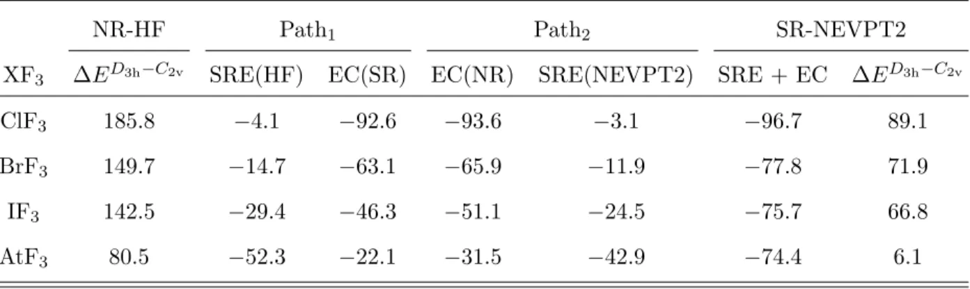
TABLE IV. Contributions (in kJ mol−1) to ∆ED3h−C2v computed at the NEVPT2 and
NEVPT2+SOC levels using SA-CASSCF(20/12) references and 21S20T averaging and state-interaction spaces. The reference (SO-)CCSD(T) ∆ED3h−C2v values are also recalled for convenience.
System
NEVPT2 NEVPT2+SOC (SO-)CCSD(T)
∆ED3h−C2v ED3h SOC E C2v SOC ∆E D3h−C2v SOC ∆ED3h −C2v ∆ED3h−C2v ClF3 88.6 −0.1 −0.1 −0.0 88.6 96.7 BrF3 72.0 −1.2 −1.0 −0.2 71.8 70.7 IF3 66.2 −6.1 −5.4 −0.7 65.5 67.89 AtF3 7.4 −58.8 −58.1 −0.7 6.7 7.79
FIG. 6. Scheme representing the two different pathways used to define the contributions of scalar relativistic effects (SRE) and electron correlation (EC) on ∆ED3h−C2v.
the series, namely scalar relativistic effects (SRE) and electron correlation (EC), NR-HF, SR-HF, NR-NEVPT2(20/12) and SR-NEVPT2(20/12) calculations have been performed with uncontracted SARC-TZVP-DKH basis sets (see Table V). It allows us to define SRE
and EC contributions to the SR ∆ED3h−C2v values through two paths: (i) Path
1 in which
SRE are first introduced at the non-correlated HF level, prior to introducing EC at the SR
level, and (ii) Path2 in which EC is introduced in the absence of SRE and SRE are later
introduced at the NEVPT2 correlated level (see Figure 6). If SRE and EC were additive,
both paths would yield the same SRE and EC contributions to ∆ED3h−C2v. One concludes
that it is not the case by looking at the data reported in Table V, i.e. SRE and EC interfere.
In the X = Cl–I cases, ∆ED3h−C2v is more affected by EC than by SRE. In contrast, an
opposite behavior is observed in the AtF3 case, which furthermore displays a particularly
large interference between SRE and EC: the sum of SRE(HF) and EC(NR) contributions is
about ∼ 20 kJ mol−1 over the sum of the EC(SR) and SRE(NEVPT2) contributions. Note
that although the NR-HF ∆ED3h−C2v values are too large compared to the SR-NEVPT2 ones,
they already exhibit a correct trend within the series. Indeed, the simultaneous treatment of
both SRE and EC affects in a similar way the ∆ED3h−C2v values (with respect to the NR-HF
ones), with only a small noticeable difference for the ClF3 case (SRE and EC decrease more
∆ED3h−C2v than in the other cases).
TABLE V. Contributions (in kJ mol−1) of scalar relativistic effects (SRE) and electron correlation (EC) to ∆ED3h−C2v according to the two pathways represented in Figure 6.
NR-HF Path1 Path2 SR-NEVPT2
XF3 ∆ED3h−C2v SRE(HF) EC(SR) EC(NR) SRE(NEVPT2) SRE + EC ∆ED3h−C2v
ClF3 185.8 −4.1 −92.6 −93.6 −3.1 −96.7 89.1
BrF3 149.7 −14.7 −63.1 −65.9 −11.9 −77.8 71.9
IF3 142.5 −29.4 −46.3 −51.1 −24.5 −75.7 66.8
AtF3 80.5 −52.3 −22.1 −31.5 −42.9 −74.4 6.1
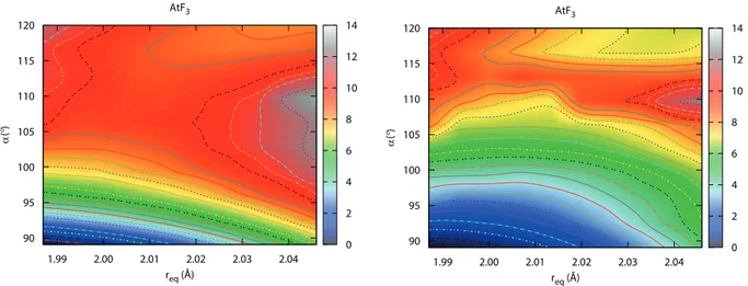
In order to assess the existence of the low TS connecting D3h and C2v minima in the
AtF3 system, one has to go beyond single-point calculations. We have considered scans
of the ground state PES between the D3h and C2v structures via NEVPT2(20/12) and
AtF3 1.99 2.00 2.01 2.02 2.03 2.04 req (Å) 90 95 100 105 110 115 120 α ( °) 0 2 4 6 8 10 12 14 AtF3 1.99 2.00 2.01 2.02 2.03 2.04 req (Å) 90 95 100 105 110 115 120 α ( °) 0 2 4 6 8 10 12 14
FIG. 7. Representation of the NEVPT2(20/12) (left) and NEVPT2(20/12)+SOC (right) ground state PESs of AtF3. The energy scale is expressed in kJ mol−1 and the T-shaped C2v energies are chosen as the zeroes of energy.
which were all varied in contrast to previous studies.2,5,9 In order to approximately determine
the minimum energy path, a non-uniform grid has been defined by interpolations between the
D3h and C2v structures. In Figure 7, contour plots of the resulting surfaces are represented.
Note that for each req value corresponds a different rax value. The approximate structures of
the D3h and C2v minima at NEVPT2+SOC level do not differ much from the ones optimized
at the SO-PBE0 level. As can also be seen, the Y-shaped C2v TS is evidenced between the
D3h and C2v minima at both NEVPT2 and NEVPT2+SOC levels. Its approximate structure
complies with the previous findings: α smaller than 120◦, rax larger than re and req smaller
than re (not explicitly shown on Figure 7). Notable SOC effects on the PES are evidenced
by the comparison of the NEVPT2 and NEVPT2+SOC scans displayed in Figure 7. It is
clear that the energy difference between the D3h and C2v minima, and to a lesser extend,
the one between the Y-shaped C2v TS and the C2v minimum are decreased, i.e. the PES
is “flattened” by SOC. This does agree with the reference SO-CCSD(T) calculations, where
SOC reduces about 8 kJ mol−1 the energy difference between the D3h and C2v minima.9
Finally, we have analyzed the factors affecting the energy difference between the Y-shaped
C2v TS and the D3h minimum by means of single-point calculations, performed on the
SO-PBE0 geometries. The results gathered in Table VI show that SRE and EC are the main contributions and are both responsible for the existence of the Y-shaped TS. Indeed, SRE and
EC tend to enlarge the energy difference, resulting in a C2v TS lying at higher energy than
the D3h minimum. As for the ∆ED3h−C2v energy difference, some interference appear between
SRE and EC which actually lead to a smaller energy difference than if the effects were additive. SOC does not seem to affect much the energy difference, an energy increase of only
0.3 kJ mol−1 is calculated. The latter prediction is quite consistent with previous DFT results:
the comparison of SR-PBE0 (SR-M06-2X) and SO-PBE0 (SO-M06-2X) results, points out
that SOC increases the energy difference between the Y-shaped C2v TS and the D3h minimum
by 0.6 (0.1) kJ mol−1. It is worth noting that previous SO-CCSD(T) calculations led to a
small decrease of about 1 kJ mol−1.9 Thus, it comes out that spin-dependent relativistic
effects are definitely small and somewhat bland on the relative energy of the Y-shaped C2v
TS with respect to the one of the D3h minimum.
TABLE VI. Energy difference (in kJ mol−1) between the Y-shaped TS and the D3h minimum of AtF3 (∆ETS−D3h) computed at different levels of theory (SO-PBE0 geometries are considered).
XF3 NR-HF SR-HF NR-NEVPT2 SR-NEVPT2 SR-NEVPT2+SOC
AtF3 −12.0 −2.5 −6.2 1.8 2.2
IV. CONCLUSION
In this work, the topological properties of the PESs and the molecular geometries of
the XF3 (X = Cl–At) fluorides have been studied with DFT and WFT based methods.
From a methodological point of view, several conclusions arise. First, the PBE0 functional appears better suited to describe the whole series than the M06-2X one. Regarding the multiconfigurational WFT calculations, the ground spin-orbit-free states are found to be essentially closed-shell and single-configurational, especially in the X = Br−At cases. While
spin-orbit coupling introduces some open-shell character to the AtF3 wave function, the
latter remains dominated by the ground spin-orbit-free spin-singlet HF configuration. It is an indisputable support for all the previous studies on these systems that made use of
single-determinantal or single-reference methods.1,2,4,5,9 Furthermore, we have demonstrated the
suitability of the two-step spin-orbit configuration interaction calculations, where spin-orbit coupling is introduced a posteriori as a perturbation of spin-orbit-free effects, for investigating
the XF3 PESs, although such an approach is sometimes said to be problematic for systems
containing heavy p-elements as At.54
With respect to the PES explorations, new critical points have been evidenced and notably
in the AtF3 system, three equivalent Cs TSs connecting the C2v minima between them. In
the X = Cl–I cases, Y-shaped TSs connect two equivalent T-shaped C2v minima, while in the
AtF3system, each Y-shaped TS connects a T-shaped C2v minima and the D3h minimum. The
calculated energy difference between the C2v and D3h minima is very small, and considering
the thermal and entropic contributions, no definitive conclusion can actually be given on
the nature of the AtF3 most stable structure. However, we firmly consider that the D3h
minimum would be the average structure seen from experiment, if they were possible, since the Y-shaped TSs results in trifling energy barriers between the three equivalent T-shaped
C2v minima.
Based on WFT calculations, we found in all the studied systems that scalar relativistic effects and electron correlation strongly reduce the energy differences between the T-shaped
C2v and the D3h structures by more than a factor of two. While in the X = Cl–I cases,
electron correlation plays a more important role, scalar relativistic effects are the main
contributors to the energy differences of interest in the AtF3 system. As expected in the
X = Cl–I cases, no significant spin-orbit coupling effects were found, and the latter led to a weak reduction of the energy difference when X = At. Furthermore, both scalar relativistic
effects and electron correlation inhibits the pseudo Jahn-Teller effect in the AtF3 system
by creating an energy barrier between the emerging D3h minimum and the C2v minima,
although both effects interfere. In agreement with DFT calculations, the spin-orbit coupling effects are found negligible regarding this point.
ACKNOWLEDGMENTS
The authors thank Dr R. W. A. Havenith for helpful discussions. This work has been supported by grants funded by the French National Agency for Research (ANR-2010-BLAN-0807) and with “Investissements d’Avenir” (ANR-11-EQPX-0004, ANR-11-LABX-0018). This work was performed using HPC resources from CCIPL (“Centre de Calcul Intensif des Pays de la Loire”).
REFERENCES
1R. M. Minyaev, Chem. Phys. Lett. 196, 203 (1992).
2P. Schwerdtfeger, J. Phys. Chem 100, 2968 (1996).
3A. Ricca, Chem. Phys. Lett. 323, 498 (2000).
4C. Bae, Y.-K. Han, and Y. S. Lee, J. Phys. Chem. A 107, 852 (2003).
5H. Kim, J. Choi, and Y. S. Lee, J. Phys. Chem. B 112, 16021 (2008).
6D. A. Dixon, D. J. Grant, K. O. Christe, and K. A. Peterson, J. Chem. Phys. 119, 2014
(2003).
7L. Chen, D. E. Woon, and T. H. Dunning Jr., J. Phys. Chem. A 113, 12645 (2009).
8K. S. Thanthiriwatte, M. Vasiliu, D. D. A., and C. K. O., Inorg. Chem. 51, 10966 (2012).
9D.-D. Yang and F. Wang, Phys. Chem. Chem. Phys. 14, 15816 (2012).
10E. H. Appelman, E. N. Sloth, and M. H. Studier, Inorg. Chem. 5, 766 (1966).
11R. J. Gillespie and R. S. Nyholm, Quart. Rev. Chem. Soc. 11, 339 (1957).
12R. J. Gillespie, J. Chem. Educ. 47, 18 (1970).
13D. F. Smith, J. Chem. Phys. 21, 609 (1953).
14H. S. P. Muller, Phys. Chem. Chem. Phys. 3, 1570 (2001).
15D. W. Magnuson, J. Chem. Phys. 27, 223 (1957).
16S. Hoyer and K. Seppelt, Angew. Chem. Int. Ed. 39, 1448 (2000).
17I. B. Bersuker, Chem. Rev. 113, 1351 (2013).
18T. Fleig and A. J. Sadlej, Phys. Rev. A 65, 032506 (2002).
19J. Champion, M. Seydou, A. Sabati´e-Gogova, E. Renault, G. Montavon, and N. Galland,
Phys. Chem. Chem. Phys. 13, 14984 (2011).
20J. Pilm´e, E. Renault, T. Ayed, G. Montavon, and N. Galland, J. Chem. Theor. Comput.
8, 2985–2990 (2012).
21A. Hermann, R. Hoffmann, and N. W. Ashcroft, Phys. Rev. Lett. 111, 116404 (2013).
22T. Ayed, M. Seydou, F. R´eal, G. Montavon, and N. Galland, J. Phys. Chem. B 117,
5206–5211 (2013).
23J. Pilm´e, E. Renault, F. Bassal, M. Amaouch, G. Montavon, and N. Galland, J. Chem.
Theor. Comput. 10, 4830–4841 (2014).
24A. S. P. Gomes, F. R´eal, N. Galland, C. Angeli, R. Cimiraglia, and V. Vallet, Phys. Chem.
25R. Maurice, F. R´eal, A. S. P. Gomes, V. Vallet, G. Montavon, and N. Galland, J. Chem.
Phys. 142, 094305 (2015).
26M. J. Frisch, G. W. Trucks, H. B. Schlegel, G. E. Scuseria, M. A. Robb, J. R. Cheeseman,
G. Scalmani, V. Barone, B. Mennucci, G. A. Petersson, et al.; Gaussian 09, Revision A.02 (2009), Gaussian, Inc., Wallingford CT.
27E. J. Bylaska, W. A. de Jong, N. Govind, K. Kowalski, T. P. Straatsma, M. Valiev, D.
Wang, E. Apra, T. L. Windus, J. Hammond, et al.; NWChem - A Computational Chemistry Package for Parallel Computers, Version 5.1.1 (2009), Pacifc Northwest National Laboratory, Richland, Washington, USA.
28Y. Zhao and D. G. Truhlar, Theor. Chem. Acc 120, 215 (2008).
29J. P. Perdew, M. Ernzerhof, and K. Burke, J. Chem. Phys. 105, 9982 (1996).
30C. Adamo and V. Barone, J. Chem. Phys. 110, 6158 (1999).
31K. A. Peterson, D. Figgen, E. Goll, H. Stoll, and M. Dolg, J. Chem. Phys. 119, 11113
(2003).
32K. A. Peterson, B. C. Shepler, D. Figgen, and H. Stoll, J. Phys. Chem. A 110, 13877
(2006).
33F. A. Bischoff and W. Klopper, J. Chem. Phys. 132, 094108 (2010).
34R. A. Kendall, T. H. Dunning, and R. J. Harrison, J. Chem. Phys. 96, 6796 (1992).
35D. E. Woon and T. H. Dunning, J. Chem. Phys. 98, 1358 (1993).
36F. Neese; ORCA – An Ab Initio, Density Functional and Semiempirical Program Package
(2013), version 3.0.1. Max-Planck-Institut f¨ur Bioanorganische Chemie, M¨ulheim an der
Ruhr.
37F. Weigend and R. Ahlrichs, Phys. Chem. Chem. Phys. 7, 3297 (2005).
38M. Douglas and N. M. Kroll, Ann. Phys. 82, 89 (1974).
39B. A. Hess, Phys. Rev. A 32, 756 (1985).
40B. A. Hess, Phys. Rev. A 33, 3742 (1986).
41D. A. Pantazis, X.-Y. Chen, C. R. Landis, and F. Neese, J. Chem. Theory Comput. 4,
908 (2008).
42B. O. Roos, P. R. Taylor, and P. E. M. Siegbahn, Chem. Phys. 48, 157 (1980).
43B. O. Roos, in Theory and applications of computational chemistry: The first forty years,
edited by C. E. Dykstra, G. Frenking, K. S. Kim, and G. E. Scuseria (Elsevier, Amsterdam, 2005) Chap. 25, pp. 725–764.
44B. A. Hess, C. M. Marian, U. Wahlgren, and O. Gropen, Chem. Phys. Lett. 251, 365
(1996).
45F. Neese, J. Chem. Phys. 122, 034107 (2005).
46C. Angeli, R. Cimiraglia, and J.-P. Malrieu, Chem. Phys. Lett. 350, 297 (2001).
47D. A. Pantazis and F. Neese, Theor. Chem. Acc. 131, 1292 (2012).
48P. Valtazanos and K. Ruedenberg, Theor. Chim. Acta 69, 281 (1986).
49P. Mezey, Potential Energy Hypersurfaces (Elsevier, Amsterdam, 1987).
50M. Mauksch and P. R. Schleyer, Inorg. Chem. 40, 1756 (2001).
51J. N. Murrell and K. J. Laidler, Trans. Faraday Soc. 64, 371 (1968).
52R. E. Stanton and J. W. McIver, J. Am. Chem. Soc. 97, 3632 (1975).
53See Supplementary Material Document No. for dissociation energies computed at
(SO-)PBE0 levels, contributions to ∆ED3h−C2v computed at the NEVTPT2 and
NEVPT2+SOC levels using SA-CASSCF(2/3) references and 6S3T/3S2T state-averaging and state-interaction spaces, as well as at the CASSCF and CASSCF+SOC levels using SA-CASSCF(20/12) references and 21S20T state-averaging and state-interaction spaces.
54M. Reiher and A. Wolf, Relativistic Quantum Chemistry: The Fundamental Theory of