HAL Id: hal-00451934
https://hal.archives-ouvertes.fr/hal-00451934
Submitted on 25 Jun 2019
HAL is a multi-disciplinary open access
archive for the deposit and dissemination of
sci-entific research documents, whether they are
pub-lished or not. The documents may come from
teaching and research institutions in France or
abroad, or from public or private research centers.
L’archive ouverte pluridisciplinaire HAL, est
destinée au dépôt et à la diffusion de documents
scientifiques de niveau recherche, publiés ou non,
émanant des établissements d’enseignement et de
recherche français ou étrangers, des laboratoires
publics ou privés.
Structure
Vigen Arakelian, Sébastien Briot, Victor Glazunov
To cite this version:
Vigen Arakelian, Sébastien Briot, Victor Glazunov. Improvement of Functional Performance of Spatial
Parallel Manipulators Using Mechanisms of Variable Structure. 12th IFToMM World Congress, Jun
2007, Besançon, France. �hal-00451934�
Improvement of functional performance of spatial parallel manipulators
using mechanisms of variable structure
Vigen Arakelian
*Sébastien Briot
†Victor Glazunov
‡Département de Génie Mécanique et Automatique
L.G.C.G.M. – EA3913
Institut National des Sciences Appliquées (I.N.S.A.)
20 avenue des buttes de Coësmes – CS 14315
F-35043 Rennes, France
Mechanical Enginneering
Research Institute
Russian Academy of Sciences
M.Kharitonyevski str. 4,
101990 Moscow, Russia
* E-mail: vigen.arakelyan@insa-rennes.fr † E-mail: sebastien.briot@ens.insa-rennes.fr ‡ E-mail: vaglznv@mail.ru
Abstract—A procedure for the increase of singularity-free zones in the workspace of spatial parallel manipulators is presented in this paper. The procedure is based on the control of the pressure angles in the joints of the manipulator. The zones, which cannot be reached by the manipulator, are detected. For increase of the reachable workspace of the manipulator the legs of variable structure are proposed. The design of the optimal structure of the spatial parallel manipulator 3-RPS is illustrated by a numerical simulation.
Keywords: Parallel manipulator, optimal control, singularity-free zones, pressure angle, force transmission
I. Introduction
It is well-known that the multiple closed chains in parallel manipulators often lead to difficulties in their design and control. One of the most important problems in the design of parallel mechanisms is the study of their singular configurations. The singular analysis has attracted the attention of several researchers and different studies have been published [1-11]. These studies are often developed for design of parallel mechanisms without singular configurations. It would be very suitable if such a result could be achieved by optimal legs assembly.
However, in the previous works, there is another trend which consists in the elimination of singular zones from the whole workspace of the manipulator by the limitation of the workspace. Thus, the workspace of the parallel manipulators which is less than the serial manipulators becomes smaller and limits their functional performances. This has led some
researchers to the problem of the optimal control of the parallel manipulators with singular configurations. Alvan and Slousch [12] suggested a solution based on the following considerations: the well known Gough-Steward platform is modified and two legs are added, then the optimal control of the manipulator is carried out by six actuators chosen from eight. As an optimization criterion the algebraic value of the Jacobian matrices and the minimum sum of the root-mean-square value of the input torques are used.
The introduction in the initial system of complementary actuators, which make it possible to eliminate the singular configurations of the parallel manipulator by means of optimal control of the motion, can be exerted. However, it is an expensive solution because of the additional actuators (it is well known that the actuators are one of the most expensive components of manipulators) and the complicated control of the manipulator caused by actuation redundancy.
In our previous work [13] the optimal control of planar parallel manipulators was studied and a new solution of this problem was proposed. It carried out by using mechanisms of variable structure, i.e. a mechanism whose structure parameters can be altered. With regard to the determination of singularity zones inside the workspace of the manipulator we proposed a kinetostatic approach taking account of the force transmission.
In this paper a similar problem for spatial parallel manipulators is studied and a procedure for the increase of singularity-free zones in the workspace of spatial parallel manipulators is presented.
II. Force transmissivity analysis
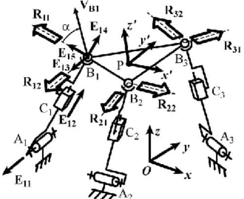
Let us consider a spatial parallel manipulator (Fig. 1) with 3 degrees of freedom (two orientations and one translation) [14], which consists of the base A1A2A3,
the output link B1B2B3 and 3 identical legs composed
of one revolute pair Ai, one prismatic pair Ci and one
spherical pair Bi (i = 1,2,3).
Fig. 1. Spatial parallel manipulator 3-RPS. Let us examine the pressure angles of the considered manipulator [15]. Let the revolute pairs Ai
be actuated and passive joints be located at Bi and Ci.
Thus, each kinematic chain includes one actuated and two passive pairs. The wrench acting to the output link is reciprocal to the unit vectors situated along the axes of non-actuated pairs. Let Ei1, Ei2, Ei3 Ei4, Ei5 (Fig. 1)
be the unit vectors of the axes of kinematic pairs, where i (i=1,2,3) is the number of the chain. Here Ei1
corresponds to rotating actuated pair, Ei2 corresponds
to sliding passive pair, Ei3 Ei4, Ei5 correspond to the
spherical passive pair. The Plücker co-ordinates of these unit screws can be described in the matrix (E)i.
z i y i z i z i y i x i z i y i z i z i y i x i z i y i z i z i y i x i z i y i z i z i y i z i z i y i x i i e e e e e e e e e e e e e e e e e e e e e e e e e e e 5 5 5 5 5 5 4 4 4 4 4 4 3 3 3 3 3 3 2 2 2 1 1 1 1 1 1 0 0 0 (E)
Here Ei1, Ei3 Ei4, Ei5 are the unit screws of zero pitch,
i.e. ei1xei01xei1yei01yei1zei01z0, etc., Ei2 is the
unit screw of infinite pitch, ei02x(xBixAi)/li, i Ai Bi y i y y l e02 ( )/ , ei z (zBi zAi)/li 0
2 , xAi, xBi, yAi, yBi,
zAi, zBi are the coordinates of the points Ai and Bi, li is
the distance between the points Ai and Bi, i=1,2,3.
Without interruption of generality we can assume that
Ei3 is parallel to Ei1, Ei4 is parallel to Ei2, and Ei5 is
perpendicular to Ei4 and Ei2.
The determinant of the matrix (E)i vanishes if the
axes Ei1 and Ei3 coincide. It means the occurrence of
singularity when the actuator causes only rotation in the joint Ei3.
We can obtain the wrenches which are reciprocal to the unit vectors of the axes of the passive kinematic pairs. The conditions of reciprocity are:
0 0 2 0 2 0 2xix i y iy i ziz i r e r e r e , 0 0 3 0 3 0 3 0 3 0 3 0 3x ix i yiy iziz ixix i yiy iz iz i r e r e r e r e r e r e 0 0 4 0 4 0 4 0 4 0 4 0 4xix i yiy i ziz i xix i y iy iziz i r e r e r e r e r e r e (1) 0 0 5 0 5 0 5 0 5 0 5 0 5x ix iy iy iz iz i xix i yiy iziz i r e r e r e r e r e r e Here , , , 0, 0, 0 iz iy ix ix iy ix r r r r r
r are the Plücker
co-ordinates of the wrenches to be found. Equations (1) mean that each connecting kinematic chain determines two wrenches of zero pitch (vector)
0
1 0 1 0 1 1 1 1 1 ix iy ix ix iy iz i r r r r r r R and
0
2 0 2 0 2 2 2 2 2 ix i y ix i x i y i z i r r r r r rR (i=1,2,3). They are
perpendicular to the axis Ei2 and intersect the point Bi.
Without the loss of generality we can assume that Ri1 is
perpendicular to Ei1 and coincides with Ei5, and Ri2 is
parallel to Ei1 and coincides with Ei3. The coordinates
of wrenches in the form of the matrix (R) 6×6 are given by: z y x z y x z y x z y x z y x z y x z y x z y x z y x z y x z y x z y x r r r r r r r r r r r r r r r r r r r r r r r r r r r r r r r r r r r r 32 32 32 32 32 32 31 31 31 31 31 31 22 22 22 22 22 22 21 21 21 21 21 21 12 12 12 12 12 12 11 11 11 11 11 11 (R)
In singular configurations the system of the wrenches
(R) degenerates.
To find the pressure angles we consider the wrenches Rij and the directions of the velocities of the
points Bi [11]. The velocity of the point B1 is
determined by the equations expressing the Plücker co-ordinates
1x
1y
1zv
1xv
1yv
1z
of the twist Ω1 existing by fixed actuated pairs A2 and A3.
0 ... 0 ... 0 ... 0 ... 0 ... ... ... 1 32 1 32 1 32 1 31 1 31 1 31 1 22 1 22 1 22 1 21 1 21 1 21 1 12 1 12 1 12 0 11 11 11 11 11 1 11 1 11 1 11 z z y y x x z z y y x x z z y y x x z z y y x x z z y y x x z z x x z z y y x x v r r r v r r r v r r r v r r r v r r r e r e r v r r r (2)Here ω11 is the generalized velocity in the pair A11. The
left hand sides of the equations (2) express the reciprocal moments of the twist Ω1 and the wrenches
R11, R12, R21, R22, R31, R32. According to the last five
equations the twist Ω1 is reciprocal with the wrenches
R12, R21, R22, R31, R32. The right hand sides of the first
and second equations correspond to reciprocal moments of the twist E11ω11 and the wrenches R11 and
As the wrench R11 is of zero pitch and parallel to
E11 then the reciprocal moment of this wrench and the
twist E11ω11 can be written as:
r11xe11x r11ze110z
11l1 r211x r211y r211z11 ...
.
As the wrench R12 is perpendicular to the E11 then the
reciprocal moment of this wrench and the twist E11ω11
is equal to zero:
12 11 ... 12 110
0 11r xe x r ze z . All the wrenches R11, R12,
R21, R22, R31, R32 are of zero pitch therefore the
reciprocal moment of the twist Ω1 and the wrench R11
can be written as:
z z B y y B x x B z z y y x x r r v V r V r V r r111 111 ... 11 1 1 11 1 11 1 11
where VB1x, VB1y, VB1z are the co-ordinates of the
velocity VB1 of the point B1:
, 1 1 1 1 1 1x x y B z B B V z y V VB1yV1y1zxB11xzB1, , 1 1 1 1 1 1z z x B y B B V y x V
Finally, the pressure angle of leg 1 can be written as:
z y x z B y B x B z z B y y B x x B r r r V V V r V r V r V 11 2 11 2 11 2 1 2 1 2 1 2 11 1 11 1 11 1 1 arccos (3)
We can find two other pressure angles by a similar way.
It was noted that in the singular configurations all the pressure angles are equal to 90°. Indeed, in this case the determinant of the matrix (R) is equal to zero. Therefore the wrench R11 is reciprocal to the twi
st
Ω1and VB1xr11xVB1yr11yVB1zr11z0, i.e. cosα10,
90
α1 , the velocity VB1 is perpendicular to the
axis of the wrench R11. In this case ω11=0.
Thus, the pressure angles can be determined at the joints of each kinematic chain. In this way we could map the maximum value of the pressure angles in the whole workspace of the parallel manipulator to detect the inaccessible zones with unfavourable values of the pressure angles.
If the prescribed path of the parallel manipulator intersects any unacceptable zone in which the pressure angle has an inadmissible value the transmission of the motion can be disrupted. In this case, it is necessary to change the structural parameters of the mechanism, i.e. the input motions.
Fig. 2 shows a schematic of the modified leg with the added articulated dyad which allows changing the input motion. The rotating actuators are mounted on the base and connected by electromagnetic clutches with the links AiDi and AiCi. The input motion can be
transmitted either by the link AiDi or AiCi (i=1,2,3). In
this way we can obtain the leg of the mechanisms with different structural parameters, which changes the direction of the wrench Ri1 and allows increasing the
singularity-free zones.
Let us consider the system of wrenches existing in this case. The link BiCi is constrained by two wrenches
of zero pitch Ti1 and Ti2. The axis of the wrench Ti1 is
perpendicular to the line AiBi and the axis of the wrench
Ti2 coincides with the axis of the link CiDi. The unit
screw E’i1 of the twist of the link BiCi is reciprocal to
the wrenches Ti1 and Ti2. This twist is of zero pitch and
is parallel to the axis Ei1. The location of the axis E’i1
corresponds to the point of intersection of the wrenches
Ti1 and Ti2. If the link CiDi is perpendicular to the link BiCi then the wrenches Ti1 and Ti2 are parallel and the
instantaneous motion of the link BiCi is a translation.
The wrench Ri1 (i=1,2,3) can be determined using the
equation analogous to (1). The pressure angle can be found using the equation (3).
Fig. 2. Planar representation of the leg with variable structure.
This approach can be applied for mechanisms with different degrees of freedom and different structures of legs. Particularly at the point Ai can be situated a
universal joint. Then each kinematic chain determines only one wrench Ri whose direction can be changed by
choosing different input links. Thus, by such a way, we can determine the pressure angles corresponding to the different structures and obtain all possible workspace with singularity-free zones.
III. Optimal structural architecture of the
manipulator taking account of pressure angle
In order to obtain the best structural architecture of the manipulator for a given trajectory, in this section we describe a procedure, which allows determining the optimal system of actuation. For this purpose, at the first time, we would like to show the singularity-free zones in the workspace of the 3-RPS spatial parallel manipulator with modified legs. These zones have been determined by using the maximum acceptable values of the pressure angles.
For numerical simulation we consider a mani-pulator in which the basis triangle A1A2A3 is equilateral
with radius 0.35 m (Fig. 1) and the platform B1B2B3
also represents an equilateral triangle with radius 0.1 m. For added dyads AiDi=CiDi=0.25 m, the articulated dyads are always located on the top of the prismatic pairs as it is shown in Fig. 2 and the translations of the prismatic pairs are limited relative to the joints Ai and Ci by values (AiCi)min=(BiCi)min=0.05 m.
The origin of the fixed base frame (Oxyz) is located at the centre of the equilateral triangle A1A2A3,
the vertical axis z is orthogonal to this triangle and the screws Ei1 are tangent to the circle passing through A1A2A3.
This manipulator has three degrees of freedom and only three of the six position/orientation variables are independent. In this work, as the output parameters are defined two orientation angles 1, 2 and the
vertical position z of the platform. The angles 1, 2
can be obtained by expressing the directional cosines in terms of x-y-x Euler angles 1, 2, 3 (see the basic
kinematic equations in [14]).
Taking into account that the modified manipulator can be actuated either by links AiDi or by links AiCi,
for given output parameters (z,1,2) of the platform,
we have 8 different combinations of actuation, i.e. we have 8 different combinations of input parameters presented below (underlined letters show the input pairs, “R” for input links AiCi with input angles i and
“P” for input links AiDi with input displacements i):
RRR: RPS-RPS-RPS: q(1)=(1,2,3) RRP: RPS-RPS-RPS: q(2)=(1,2,3) RPR: RPS-RPS-RPS: q(3)=(1,2,3) RPP: RPS-RPS-RPS: q(4)=(1,2,3) PRR: RPS-RPS-RPS: q(5)=(1,2,3) PRP: RPS-RPS-RPS: q(6)=(1,2,3) PPR: RPS-RPS-RPS: q(7)=(1,2,3) PPP: RPS-RPS-RPS: q(8)=(1,2,3)
Table 1 shows the workspaces of each case of actuation for the altitude of the platform equal to 0.1 m. In these figures, several zones can be seen, which correspond to the variations of the maximum values of the pressure angle for given orientation (1,2) of the
platform. The contrast intensity shows the variations of the pressure angle (see Fig. 3).
Fig. 3. The contrast intensity corresponding to the pressure angle values.
Thus, the black zones are the surfaces where the pressure angle has inadmissible values, and as a result, these are the zones which cannot be reached and crossed by the parallel mechanism. These zones separate the workspace into different aspects, what decrease the capacity of displacement of the platform.
Fig. 4. The reachable workspace of the spatial parallel manipulator with modified legs (z = 0.1 m). Fig. 4 shows the reachable workspace of the modified parallel mechanism with legs of variable structure. We can see that the workspace of the modified manipulator is only composed of singularity-free zones and the whole workspace of the manipulator is reachable (increase until 100%).
Now we would like to describe a procedure, which allows determining the optimal system of actuation. This algorithm is based on the control of the pressure angles in the joints of the manipulator along the given trajectory. It is similar to the procedure given in [13] for planar parallel manipulators.
At first the calculation of the pressure angles in the joints along the trajectory for all possible structures of the parallel mechanism with variable architecture must be accomplished, then the best structure must be chosen for which the maximum value of the pressure angle along the trajectory is always less than the limit value. If there is no structure satisfying this condition, the given trajectory must be decomposed in several parts and the generation of the motion must be carried out by different structures. It is obvious that in this case it would be desirable that the trajectory can be realized by minimal structural changes.
A numerical example is considered below in order to illustrate the application of the suggested design procedure.
For given parallel manipulator (Fig. 1) with legs of variable structure (Fig. 2) generate the trajectory from the initial position P1 (z=0.3 m, 1=0 rad., 2=0 rad.) to
the final position P2 (z=0.3 m, 1=0 rad., 2=1 rad.),
keeping z and 1 constant.
Estimation of the pressure angle along the given trajectory shows that the best structural solution for generation of motion is the RPS-RPS-RPS mechanism, i.e. when the first actuator is connected with the link
A1D1 and two others with the links A2C2 and A3C3. In
this case the maximum values of the pressure angles in the joints are always less than the limit value.
In order to illustrate the variations of torques for examined case we develop a model of the manipulator with the given trajectory using the ADAMS software.
A force parallel to the z-axis and equal to 100 N was applied to the platform and the friction coefficients in the prismatic pairs were equal to 0.01. The obtained torques are shown in Fig. 5. We can note that the torques have admissible values along the trajectory.
It is obvious that the similar mechanisms of variable structure can also be designed on the base of the screw or cam systems, the rhombic pantographs, etc.
(a) Actuator 1
(b) Actuator 2
(c) Actuator 3
Fig. 5. Torques of the actuators.
IV. Conclusion
A procedure for the improvement of functional performance of spatial parallel manipulators has been presented in this paper. The procedure is based on the control of the pressure angles in the joints of the manipulator along the given trajectory of the platform. The zones, which cannot be reached by the
manipulator, were detected. For increase of the reachable workspace of the manipulator the legs of variable structure were proposed. Such a solution allows obtaining the best structural architecture of the manipulator for any trajectory. The design of the optimal structure of the planar parallel manipulator 3-RPS was illustrated by a numerical simulation. We believe that the suggested method is a useful tool for the improvement of the functional performance of parallel manipulators with singular zones.
References
[1] C.M. Gosselin, J. Angeles. Singularity analysis of closed-loop kinematic chains. IEEE Transactions on Robotics and Automatics. 6(3) (1990) pp.281-290.
[2] D. Zlatanov, R.G. Fenton and B. Benhabib. Singularity analysis of mechanisms and robots via a motion-space model of the instantaneous kinematics. Proceedings of the 1994 IEEE International Conference on Robotics and Automation, 2 (1994) pp. 980-991.
[3] J.-P. Merlet. Singular configurations of parallel manipulators and Grassmann geometry. The international Journal of Robotics Research. 8(5) (1989) pp. 45-56.
[4] B.M. St-Onge, C.M. Gosselin. Singularity analysis and representation of the general Gough-Stewart platform. The International Journal of Robotics Research. 19(3) (2000) pp.271-288.
[5] F. Pernkopf, M. Husty. Singularity analysis of spatial Stewart-Gough platforms with planar base and platform. Proceedings of the DECT 2002, Montreal (2002).
[6] J.T. Wen, J.F. Oapos Brien. Singularities in three-legged platform-type parallel mechanisms. IEEE Transactions on Robotics and Automation. 19(4) (2003) pp.720- 726. [7] A. Wolf, E. Ottaviano, M. Shoham and M. Ceccarelli.
Application of line geometry and linear complex approximation to singularity analysis of the 3-DOF CaPaMan parallel manipulator. Mechanism and Machine Theory, 39 (1) (2004) pp.75-95.
[8] S. Bandyopadhyay, A. Ghosal. Analysis of configuration space singularities of closed-loop mechanisms and parallel manipulators. Mechanism and Machine Theory, 39 (5) (2004) pp.519-544.
[9] J.-S. Zhao, Z.-J. Feng, K. Zhou and J.-X. Dong. Analysis of the singularity of spatial parallel manipulator with terminal constraints. Mechanism and Machine Theory, 40(3) (2005) pp.275-284.
[10] V. Arakelian, S. Briot, V. Glazunov. Singularity analysis of the parallel manipulator PAMINSA, Journal of Machinery Manufacture and Reliability, 1 (2006) pp.80-88.
[11] Glazunov V.A. Koliskor A.Sh., Krainev A.F., and Model B.I. Classification principles and analysis methods for parallel-structure spatial mechanisms, Journal of Machinery Manufacture and Reliability, Allerton Press Inc., 1 (1990) pp. 30-37.
[12] K. Alvan, A. Slousch. On the control of the spatial parallel manipulators with several degrees of freedom. Mechanism and Machine Theory, Saint-Petersburg, n°1 (2003) pp. 63-69.
[13] V. Arakelian, S. Briot, V. Glazunov. Increase of singularity-free zones in the workspace of parallel manipulators using mechanisms of variable structure (in press)
[14] K-M. Lee, D. K. Shah. Kinematic analysis of a three DOF in-parallel actuated manipulator. IEEE Journal of Robotic and Automation, 4(3) (1988), pp. 354-360.
[15] S. Balli, S. Chand. Transmission angle in mechanisms. Mechanism and Machine Theory, 37 (2002) pp. 175-195.
(a) Actuators: RRR (b) Actuators: PPP
(c) Actuators: PRR (d) Actuators: RPP
(e) Actuators: RPR f) Actuators: PRP
(g) Actuators: RRP (h) Actuators: PPR TABLE I. Maximum values of the pressure angles (z = 0.1m)