SN Applied Sciences (2021) 3:196 | https://doi.org/10.1007/s42452-020-04133-8
Effect of carbon anode production parameters on anode cracking
Salah Amrani1 · Duygu Kocaefe1 · Yasar Kocaefe1 · Dipankar Bhattacharyay1,3 · Mohamed Bouazara1 · Jules Côté2 Received: 23 September 2020 / Accepted: 30 December 2020
© The Author(s) 2021 OPEN
Abstract
Carbon anodes are used in the electrolytic production of aluminum. The quality of anodes is directly related to the pro-duction cost, carbon and energy consumption, and environmental emissions. It is desired that the anodes have high density, low porosity/cracks, low electrical resistivity as well as low air and CO2 reactivities. Low resistivity of anodes reduces energy required to produce aluminum during electrolysis. The presence of cracks and pores increases the anode electrical resistivity. Therefore, it is important to know how and when the pores and cracks form during the anode pro-duction so that the necessary actions could be taken to prevent their formation. A study was carried out to investigate the effect of different anode production parameters such as anode composition, type of raw material used, time and top-former bellow pressure of vibro-compactor, green anode cooling medium, and heating rate used during baking on the crack formation. The anodes are fabricated at the carbon laboratory of University of Quebec at Chicoutimi (UQAC) and characterized by measuring their properties (density, electrical resistivity, and surface crack density). The anode properties, hence the anode quality, were correlated with the anode production parameters. Also, their tomographic analysis was carried out to visualize and quantify the internal cracks.
Graphical abstract
Keywords Aluminum production · Carbon anode · Vibro-compaction · Anode baking · Characterization
* Duygu Kocaefe, [email protected] | 1Alouette Research Chair On Carbon, Aluminium Research Centre (REGAL),
UQAC/Aluminerie University of Québec at ChicoutimiUniversity of Québec, Chicoutimi, Québec G7H 2B1, Canada. 2Aluminerie Alouette
Inc, 400, Chemin de la Pointe-Noire, Sept-Îles, Québec G4R 5M9, Canada. 3Centurion University of Technology and Management, R.Sitapur,
1 Introduction
Aluminum is produced by electrolysis using the Hall-Héroult process according to the reaction:
The carbon required for aluminum production via electrolytic alumina (Al2O3) reduction is supplied by the carbon anodes which are consumed during electrolysis. The cost of anodes is around 15% of the total cost of alu-minum production [1]. However, this can increase to 25% due to over-consumption of carbon if the anode quality is poor. The quality of the anodes has a major influence on the efficiency of the electrolysis. Each anode has a certain porosity and some cracks, which is inevitable. However, the presence of excessive cracks/pores is considered a sign of poor anode quality since they increase the electrical resistivity of anodes, hence the energy needed for elec-trolysis. They also decrease anode density. In addition, the utilization of poor-quality anodes results in shorter anode life (increased anode consumption and production cost) and increases greenhouse gas (GHG) emissions.
Modern electrolysis cells use prebaked anodes. Dur-ing anode production, dry aggregate (petroleum coke, rejected green and baked anodes, and butts) with a desired granulometry is mixed with coal tar pitch, which acts as the binder, to produce anode paste. Then, anode paste is compacted in a vibro-compactor or a press to obtain green anodes, which are baked in large furnaces to produce baked anodes. These are used in electrolysis after rodding. All the anode production parameters affect the anode quality.
The current study was carried out to investigate the effect of the different parameters (anode composition, raw materials, time and top-former bellow pressure of vibro-compactor, medium used to cool the green anodes, and heating rate used during baking) to determine the influ-ence of production conditions on anode cracking.
There are some studies reported in the literature on the formation of cracks and their effect on anode quality. The quality of raw materials and the anode recipe used can affect the anode quality. Utilization of suitable anode recipe, where fines are filling the spaces between the par-ticles are important. Use of high quantity of butts might result in cracks since the thermal expansions of butts and the rest of the dry aggregate are different. The stress cre-ated during baking at the positions where butt is present might cause new cracks to form [2, 3].
Utilization of coke with high expansion coefficient and low grain stability can form cracks [4]. Coke with high resiliency can also cause cracking due to spring-back effect. High sulfur content cokes may lead to cracking if (1) 2Al2O3+ 3C → 4Al + 3CO2
the baking temperature is high. Suitable levels of pitch content and aggregate sizing are required to prevent any excessive shrinkage or expansion, thus, crack and porosity formation [3]. If the anode is under-pitched (not enough pitch), air is trapped between the aggregate particles as well as in the pores of the particles. These anodes are con-sumed quickly in the cell. If the anode is over-pitched (too much pitch), the cracks can form due to high quantity of volatile release during baking [5]. In addition, butts con-tain sodium which increases the anode reactivity, thus anode consumption [6].
Binder pitch can influence the green anode density of the anodes. Good and homogeneous pitch distribution can reduce the air trapped between the coke aggregates in green anodes [7]. Different plants use different parti-cle size distribution (anode recipe) to have good qual-ity anodes. Particle size distribution not only affects the anode density, but it also influences the air permeability [8], pore size distribution [9], mechanical strength, electri-cal resistivity [3], reactivity and even chemical composition of anodes [10].
Mixing parameters (mixing time, mixing speed, mixing temperature) are important [3, 11] for anode quality. If the mixing of dry aggregate and pitch is not done properly, the anodes become non-homogeneous. Then, the cracks will form in pitch rich regions during pitch devolatiliza-tion. Homogeneous anode paste reduces the pitch con-sumption and high local volatile release leading to lower internal pressure and cracking rate during anode baking [12, 13].
Vibro-compaction parameters (paste temperature, forming temperature, and vibration time) have to be well adjusted to avoid excessive cracking [4]. If the compaction time is too short, the anode is under-compacted, which decreases the anode density and increases the porosity as well as dusting. On the other hand, long compaction times lead to over-compaction of the anode. This results in stress formation yielding to cracks and delamination [15]. Hulse [3], Tkac [9], and Sanogo [16] showed the effect of compac-tion time on the anode properties and proposed a method to determine the optimum compaction time. The results indicated that there is indeed an optimal vibration time. Exceeding this time deteriorates the mechanical proper-ties and increases the electrical resistivity. In addition to compaction time, compaction force (load and vibro-com-pactor top-former bellow pressure), vibration frequency, and the utilization of vacuum are the parameters which can affect the anode quality [14]. Furthermore, the utili-zation of vacuum during vibro-compaction helps remove the trapped air between the particles as well as in the coke pores and facilitates the penetration of pitch.
The green anodes are baked for about two to three weeks in baking furnaces at temperatures up to around 1150 °C
before being used in electrolysis. Pitch carbonizes and links aggregate particles together [17]. During baking, there are two temperature regions that are critical for cracking. Up to 150 °C, stresses formed during compaction and paste cool-ing are released leadcool-ing to anode expansion [18, 19]. If these stresses exceed a certain limit, cracks can form. Cracks can appear as well during baking in the temperature range of 200 °C to 600 °C if the gas pressure builds up excessively due to devolatilization of pitch especially if high heating rates are used [4, 20, 24]. As previously mentioned, a better distribution of pitch in the anode block causes a reduction in the internal pressure (due to the devolatilization) during baking; this leads to an anode with fewer cracks [13]. The anode life and carbon consumption is strongly affected by baking parameters [21]. The cracking can also be provoked if large temperature gradients exists in the anode [22]. Sendid and Courau [23] reported that the propagation of existing cracks is also a major source of anode cracking.
This paper reports the effect of different operational parameters on the cracking of anodes produced, conse-quently on anode properties. The anodes were produced using the same raw material and under the same operating conditions except the parameter to be studied is varied. Also, tomographic analyses of the anodes were carried out. This approach makes the systemic investigation of cracking pos-sible. Anodes were characterized measuring the apparent density, electrical resistivity, surface crack density, internal defects (cracks/pores), and the optical density. The number and percentage of internal defects were calculated from the tomography results with the software developed by the car-bon group at UQAC in order to visualize and quantify the cracks/pores.
Previously, the carbon group of UQAC developed a spe-cial equipment (SERMA) to determine how the anode elec-trical resistance varies with time during baking [24, 25]. The resistivity variation is directly proportional to crack forma-tion since cracks increase resistivity. This study shows the evolution of crack formation during baking. Many param-eters affect the crack formation as given in the present arti-cle, and the cracks form primarily during baking. It should be noted that it is impossible to determine exactly which crack forms at what time in such materials. Materials and methods used are described in the following section. Then, the results are presented and discussed. At the end, the conclusions are given.
2 Materials and methods
2.1 Properties of raw materials
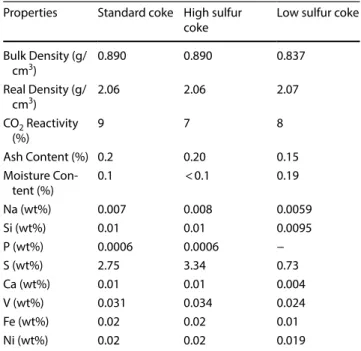
Three petroleum cokes and one coal tar pitch were used for the pilot scale anode production. Tables 1 and 2 pre-sent the properties of cokes and pitch.
2.2 Anode production
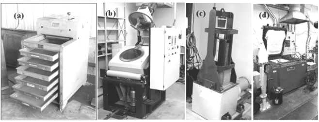
Anodes weighing about 10 kg were produced at the car-bon laboratory of UQAC. First, the dry aggregate (coke, butt, rejected anodes) was sieved to have the desired particle size distribution required for the anode recipe (Fig. 1a). After preheating the coke and the pitch, the
Table 1 Physical and chemical properties of coke
Properties Standard coke High sulfur
coke Low sulfur coke
Bulk Density (g/ cm3) 0.890 0.890 0.837 Real Density (g/ cm3) 2.06 2.06 2.07 CO2 Reactivity (%) 9 7 8 Ash Content (%) 0.2 0.20 0.15 Moisture Con-tent (%) 0.1 < 0.1 0.19 Na (wt%) 0.007 0.008 0.0059 Si (wt%) 0.01 0.01 0.0095 P (wt%) 0.0006 0.0006 − S (wt%) 2.75 3.34 0.73 Ca (wt%) 0.01 0.01 0.004 V (wt%) 0.031 0.034 0.024 Fe (wt%) 0.02 0.02 0.01 Ni (wt%) 0.02 0.02 0.019
Table 2 Physical and chemical properties of pitch
Properties Pitch Ash at 900 °C (% m/m) 0.12 β Resin (% m/m) 22.2 Density at 20 °C (g/cm3) 1.320 Quinoline insolubles (% m/m) 6.9 Toluene insolubles (% m/m) 29.1 Coking Value (% m/m) 59.1 Softening Point (°C) 119.6
Dynamic Viscosity 170 °C (mPa.s) 1390
anode paste was prepared in an intensive mixer (Fig. 1b). The green anodes were prepared using raw materials, anode recipe, and the production conditions similar to those used in industry. Then, the paste was compacted in a vibro-compactor equipped with vacuum (Fig. 1c). The compaction was monitored with two sensors to ensure that the vertical displacement of load and the table were synchronized. At the end of compaction, the anode is removed from the mould and was allowed to cool down. The mixer and the vibro-compactor were designed by the carbon group of UQAC. The green anodes were baked in a PYRADIA (Model No-B07D02029021SVCCH) furnace (Fig. 1d). Anodes were placed in a ceramic box, covered with packing coke, and baked at a predeter-mined heating rate up to a desired temperature. The temperature distribution in the furnace was monitored placing a number of thermocouples inside the furnace. After baking, anodes were kept at this temperature for a certain soaking period. The properties of the laboratory anodes are similar to those of the industrial anodes [26]. 2.2.1 Anode production parameters
In the first part of the study, the effect of raw materials and the vibration time on the anode quality were investi-gated. The quantities of ball mill product (BMP) and filter dust (FP) were kept constant. In the modified anode recipe, the percentage of coarse particles and medium particles were varied. The mixing temperature was 170 °C. The maximum baking temperature and the soaking time were 1050 °C and 8 h, respectively. The conditions were similar to the ones used by the industry except for the parameter being studied. Only the soaking time is shorter than the one used in the industry. The objective of soaking is to have a uniform temperature distribution in order to attain
uniform properties in the anode since the anode proper-ties are highly dependent on temperature. However, the industrial anodes are much bigger (around 1 ton) than the laboratory anodes. Therefore, a period of 8 h soaking time was enough for the laboratory anodes. The properties of the laboratory anodes produced were similar to those of the industrial anodes.
Table 3 summarizes the experimental conditions. Three groups of anodes were prepared and baked. In the first group of experiments, the effect of raw materials (anode recipe, butt and pitch percentage) on anode properties and cracking was studied.
In the second part, green anodes were made using the same raw materials but under different operating condi-tions (vibration time, top-former bellow pressure, and cooling medium). The effect of green anode production conditions on the anode cracking problem was studied.
In the third group, eight anodes were produced. Four of these anodes had the same percentage of butts used in a standard anode recipe and the other four anodes did not contain any butts. Anodes were baked at four different heating rates (15 °C/h, 11 °C/h, 7 °C/h, and combination (heating rate varied during baking): 15–7-15 °C/h). In this part, the effect heating rate on anode properties as well as cracking was studied in the presence and absence of butts. The evolution of crack formation at the intermediate stages of baking was given elsewhere [26, 27].
2.2.2 Anode characterization
Different properties of anodes were measured to char-acterize them. The measurement methods are described below.
2.2.2.1 Apparent density of anodes The apparent den-sity was determined according to the ASTM D5502-00 (2005) standard. Cylindrical cores of 50 mm diameter and 130 mm length were used. The core lengths were ured at four different positions and diameters were meas-ured at eight positions. Their averages were used to cal-culate the core volume. Knowing the core weight and the volume, the density was calculated.
2.2.2.2 Electrical resistivity of anodes The specific electri-cal resistivity was measured with anode cores of 50 mm in diameter and 130 mm in length using ASTM D6120 9 (2007).
The specific electrical resistivity distribution was measured in both green and baked anodes using a lab-oratory model of the SERMA (Specific Electrical Resis-tivity Measurement of Anodes) technology, which was developed previously by the UQAC carbon group. It con-sists of two plates equipped with a number of current and voltage probe pairs. When these plates come in to contact with opposing anode surfaces, a total current of 5 A is applied from the current probes on one sur-face. Then, the corresponding voltage drops are meas-ured from each voltage probe pair in the vicinity of each current probe pair between the two plates using a data acquisition system. The resistivities are then calculated
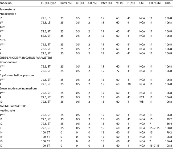
Table 3 Experimental conditions
FC, Fresh coke; BR, Baked rejects; GR, Green rejects; VT, Vibration time; P, Top-former bellow pressure; CM, Green anode cooling medium; HR, Heating rate; BT, Baking time; LS, Low sulfur coke; ST standard coke; NCA: Natural convection in air; FCA, Forced convection with air; WB: Water bath; *Standard anode recipe, low sulfur coke; **Modified anode recipe—low sulfur coke; ***Standard anode recipe—standard coke
Anode no FC (%), Type Butts (%) BR (%) GR (%) Pitch (%) VT (s) P (psi) CM HR (°C/h) BT(h) Raw material Anode recipe 1* 72.5, LS 25 0.5 2 15 60 41 NCA 11 106.8 2** 72.5, LS 25 0.5 2 15 60 41 NCA 11 106.8 Butt 3*** 72.5, ST 25 0.5 2 15 60 41 NCA 11 106.8 4 62.5, ST 35 0.5 2 15 60 41 NCA 11 106.8 Pitch 3*** 72.5, ST 25 0.5 2 15 60 41 NCA 11 106.8 5 72.5, ST 25 0.5 2 13 60 41 NCA 11 106.8 6 72.5, ST 25 0.5 2 18 60 41 NCA 11 106.8
GREEN ANODE FABRICATION PARAMETERS Vibration time
3*** 72.5, ST 25 0.5 2 15 60 41 NCA 11 106.8
7 72.5, ST 25 0.5 2 15 72 41 NCA 11 106.8
Top-former bellow pressure
3*** 72.5, ST 25 0.5 2 15 60 41 NCA 11 106.8
8 72.5, ST 25 0.5 2 15 60 30 NCA 11 106.8
Green anode cooling medium
3*** 72.5, ST 25 0.5 2 15 60 41 NCA 11 106.8 9 72.5, ST 25 0.5 2 15 60 41 FCA 11 106.8 10 72.5, ST 25 0.5 2 15 60 41 WB 11 106.8 BAKING PARAMETERS Heating rate 3*** 72.5, ST 25 0.5 2 15 60 41 NCA 11 106.8 11 72.5, ST 25 0.5 2 15 60 41 NCA 15 79.2 12 72.5, ST 25 0.5 2 15 60 41 NCA 7 156.4 13 72.5, ST 25 0.5 2 15 60 41 NCA 15–7-15 108.8 14 100, ST 0 0 0 15 60 41 NCA 15 79.2 15 100, ST 0 0 0 15 60 41 NCA 11 106.8 16 100, ST 0 0 0 15 60 41 NCA 7 156.4 17 100, ST 0 0 0 15 60 41 NCA 15–7-15 108.8
at different positions. The details of the equipment are given elsewhere [24, 25].
2.2.2.3 Anode surface crack density (external defects) Anodes were inspected visually and the number of surface cracks were counted. The surface crack density was calculated by dividing the number of cracks by the anode surface area.
2.2.2.4 Tomography Computed tomography (CT), which is an imaging technique, constructs a 3D image of an object from a numerous 2D digital images of the same object using x-ray. 2D images of vertical planes were cre-ated using CT (Somatom Sensation 64, Institute National de Recherche Scientifique (INRS-ETE)) at every 0.6 mm of the anode along the length with a resolution of 2.381 pix-els per mm.
2.2.2.5 Optical density (tomography) Tomography gives a distribution of optical density in the object, which is the measure of the amount of material relative to void space containing air in the object (-1000 HU (Hounsfield Unit) for air where no solid is present). Optical density values give an indication of the presence of cracks and pores, which contain air only.
2.2.2.6 Internal defects (tomography) A software was developed by the UQAC carbon group using Matlab R2015a to analyze the hundreds of 2D images (on vertical planes along the height) of green and baked anodes and estimate the percentage of internal defects in the anode. Information obtained from all 2D images in a given anode permits the quantification of the results within its volume. The results are presented as one image per anode show-ing the total internal defect distribution for that anode.
3 Results and discussion
3.1 Tomographic images and electrical resistivity measurements
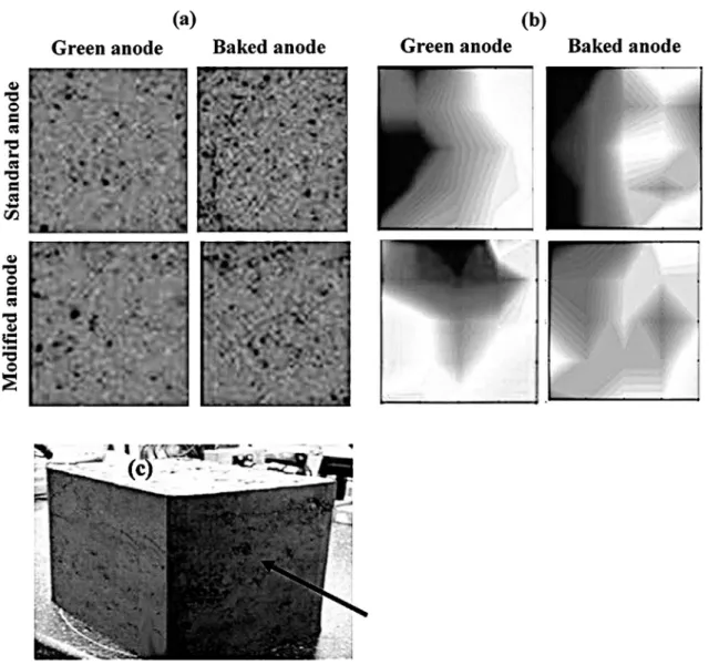
The total number of defects in anodes was determined with the software developed by the UQAC carbon group to analyze the numerous 2D images taken during tomog-raphy. An example is given in Fig. 2a for anodes 3 and 4 (Table 3). Images showing all defects along the length are presented in Fig. 2a for both green and baked anodes pro-duced with different butt contents. Darker regions corre-spond to higher number of internal defects. The resistivity maps between the small side surfaces of anodes, which were measured with the equipment developed at UQAC (SERMA), were also determined [24, 25]. These for the same
cases are shown in Fig. 2 (b). Darker regions have higher resistivities. Figure 2c shows a lab anode and the direc-tion of measurement. It should be noted that the green anode electrical resistivities are about two orders of mag-nitude greater (above 1500 μΩ·m) than those of the baked anodes. Small variations in pitch concentration in green anodes could give significant differences in the resistivity values. The baked anode resistivities, on the other hand, directly indicate the presence of pores and cracks. These figures show that the internal number of defects is higher for both green and baked anodes containing greater butt percentage compared to the standard anode. The electri-cal resistivities also show a similar trend. From these fig-ures, the agreement between the tomography and SERMA results can be seen: the zones that contain more defects (determined by the tomography) have higher resistivities (determined by SERMA). Also, the comparison of the baked and green anode resistivities shows that generally a high resistivity zone in a green anode results in a high resistivity zone after baking.
These analyses were carried out for all the cases in Table 3. Then, the overall results are determined and pre-sented in the following section.
3.2 Effect of raw materials
In this part, the effects of anode recipe and butt and pitch contents on the cracking and anode properties were inves-tigated (Table 3).
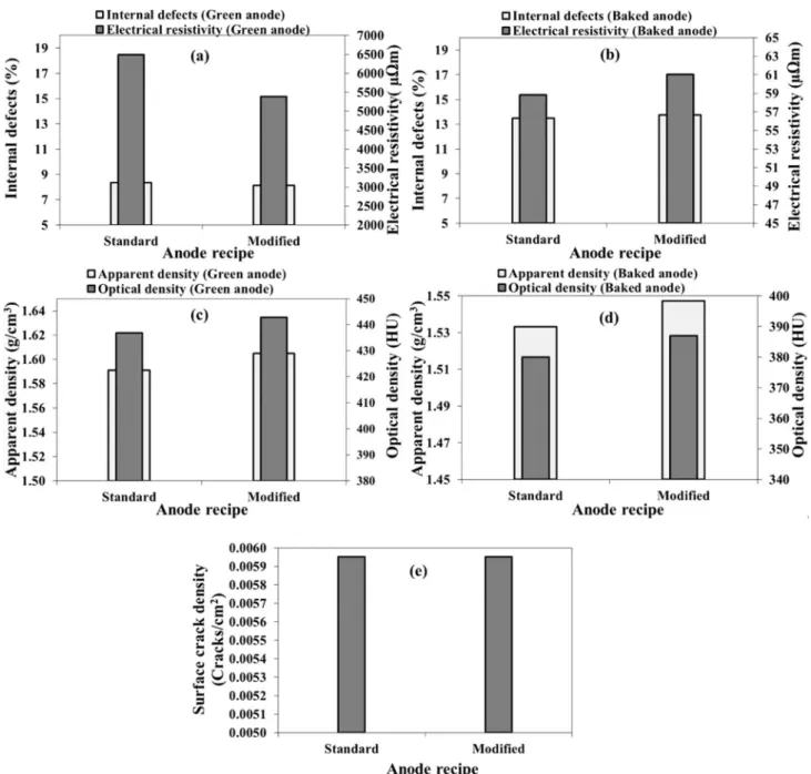
3.2.1 Anode recipe
Two anodes (anodes 1 and 2, Table 3) were produced using different particle size distributions. In anode 1, a standard anode recipe was used whereas the anode 2 was produced with a modified recipe. The recipe modification and its effect on anode properties were previously studied [2]. In this study, its effect on crack (defect) formation is studied. In the modified recipe, the fractions of medium and coarse particles were readjusted. The ultra-fine fractions (ball mill product (BMP) and filter dust (FD)) were kept similar to that of the standard recipe.
Comparing the electrical resistivity of the two green anodes (Fig. 3a) shows that the resistivity decreased when the recipe is modified; however, the number of defects remained practically the same. This indicates that the dif-ference in resistivity values is due to slight difdif-ferences in pitch distribution. On the other hand, after baking (Fig. 3b), the anode made with the modified recipe is found to have a higher resistivity compared to the anode prepared with the standard recipe. This shows that the modified recipe is likely to cause the creation of somewhat more cracks during baking. The internal defects of the baked anode
made using modified recipe is slightly higher compared to the standard anode.
A good anode density is generally considered as a sign of a good quality anode. Figure 3c presents the apparent and optical density of two green anodes made with different recipes and Fig. 3d presents the den-sities of the same anodes after baking. It can be seen that the apparent densities of both the green and the baked anodes were slightly improved when the anode recipe was modified. The optical densities of the anodes also show the same trend. The optical density, which is obtained from the tomographic analysis, indicates the relationship between solid and void space in materi-als. Higher optical density was obtained for the modi-fied aggregate which means that the solid content is higher than the void space in this anode compared to
the standard anode both before and after baking. The results of the tomographic analysis results agree with the direct measurements of the densities. The surface crack densities of both anodes are similar (Fig. 3e). The surface cracks are not good indicators of anode quality since an anode with surface cracks can have an interior structure of acceptable quality.
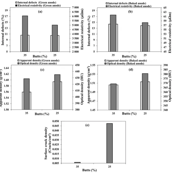
3.2.2 Butt content
Anodes 3 and 4 have different butt contents (25% and 35%, Table 3). Figure 4a and b show that increasing butt content did not influence the internal defect percent-age in green anodes but increased it slightly in baked anodes. The electrical resistivity increased as the butt content increased both for green and baked anodes.
Fig. 2 a: Map of internal defects determined from the 2D tomography images and b Electrical resistivity maps of green and baked anodes
The impact of higher butt content may be explained with the low wettability of butt with pitch matrix [28] and the difference in thermal expansion coefficients of coke and butt [2–4, 26]. This difference might create stress, consequently, anodes might crack during bak-ing. It might also be due to the insufficient pitch pen-etration into the butt pores. The results also show that increasing butt content decreased the anode apparent
and optical densities both for green and baked anodes (Fig. 4c and d). It should be noted that the percentage of pitch was not adjusted when the percentage of butt was changed. In general, the effect of butts on anode properties depends on the butt quality. Visual inspec-tion of the baked anodes indicated that the surface cracks decreased when the butt content was increased
Fig. 3 Effect of anode recipe on a–b: internal defect percentage and electrical resistivity, c–d apparent and optical densities, and e surface
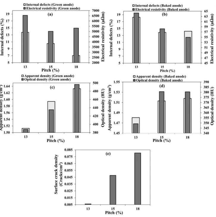
(Fig. 4e). As it was mentioned previously, surface cracks do not necessarily represent the internal anode quality. 3.2.3 Pitch content
Three different pitch percentages (13%, 15%, and 18%) were used to study the effect of this parameter on the quality of the anodes (anodes 3, 5, and 6, Table 3). The results show that the increase in the percentage of pitch decreases the internal defect percentage for green anodes
(Fig. 5a) as expected. When there is not enough pitch, pores of coke and the interparticle spaces are not com-pletely filled, resulting in a porous anode [29].
Electrical resistivity of green anodes decreased with increasing pitch content up to a certain pitch percent-age (15%), which was close to optimum pitch content. However, the electrical resistivity increased with fur-ther increase in pitch percent. When pitch fills the voids between the coke particles and the pores in the parti-cles of green anodes, the electrical resistivity decreases.
Fig. 4 Effect of butt content on: a, b internal defect percentage and electrical resistivity, c, d apparent and optical densities, and e surface
Nevertheless, if the pitch percentage is increased more, the accumulation of excess pitch between the parti-cles increases the electrical resistivity [3, 29]. This can be seen in Fig. 5a where the anode produced using 15% pitch had lower electrical resistivity than the other two anodes containing 13% and 18% pitch. For baked anodes, increasing the percentage of pitch decreased the resistivity as shown in Fig. 5b. Internal defects were slightly higher for the baked anode containing the high-est pitch percentage, which was over-pitched to some
extent. Over-pitching can cause crack formation during baking due to the higher quantity of released volatiles (Fig. 5b).
As it can be seen in Fig. 5c, both the optical and appar-ent densities increased with increasing pitch percappar-ent for green anodes. The baked anode optical and apparent densities increased appreciably when the pitch content is increased from 13 to 15%. However, further increase in pitch percent did not have a significant effect on the
Fig. 5 Effect of pitch content on: a–b internal defect percentage and electrical resistivity, c–d apparent and optical densities, and e surface
densities (Fig. 5d). The apparent density increased slightly whereas the optical density remained the same.
The results of the visual inspection (surface cracks from Fig. 5e) show that increasing the amount of pitch can cause many surface cracks, but this does not reveal the internal quality. The anode with a high percentage of pitch has a low electrical resistivity and low internal defects compared to those of the anode made with 13% pitch (Fig. 5b), but it has high surface crack density (Fig. 5e). This again shows that the quality of anodes can-not be evaluated correctly only with the visual inspec-tion of the surface.
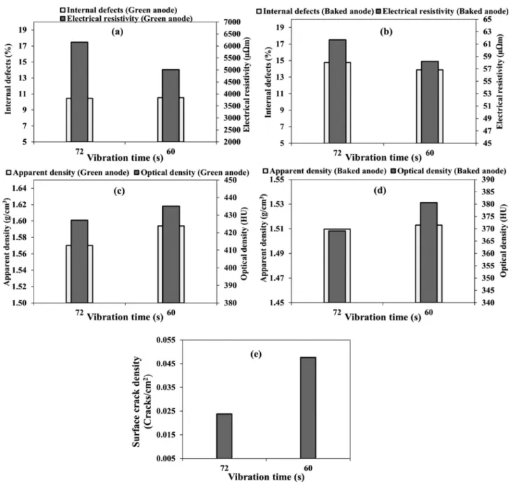
3.3 Green anode fabrication parameters 3.3.1 Vibration time
Two anodes (anodes 3 and 7) were produced using vibra-tion times of 60 and 72 s (Table 3). Figure 6 shows the effect of vibration time on internal defects, electrical resis-tivity, apparent and optical densities, and specific surface crack density.
The green and baked anodes produced using lower vibration time has lower resistivities than those of the anodes produced using a higher vibration time. This result
Fig. 6 Effect of vibration time on: a–b internal defect percentage and electrical resistivity, c–d apparent and optical densities, and e surface
indicates that the anode was over-compacted when 72 s was used. Over-compaction (too high a vibration time) causes more stress accumulation in the green anode. Both green anodes have similar amounts of defects. However, baked anode produced using a lower vibration time has a slightly lower defect percentage. Accumulation of stress during green anode formation results in defect forma-tion during baking. The electrical resistivity is lower for the anode produced using a lower vibration time for both green and baked anodes (Fig. 6a and b). However, there is a limit for decreasing the vibration time. If the anodes are not compacted enough (under-compaction), this
also increases the internal defects and the resistivity. It is important to find the optimum vibration time necessary for a given anode [16].
The results show that both green and baked anodes produced using the low vibration time has a higher appar-ent and optical densities than those of the anodes made with the higher compaction time (Fig. 6c and d).
The anode manufactured using a low vibration time has more surface cracks than that manufactured with a high compaction time (Fig. 6e). Visual inspection does not indi-cate the internal anode quality. The internal defect analy-sis show that the quality of this anode is better than the
Fig. 7 Effect of top-former bellow pressure on: a–b internal defect percentage and electrical resistivity, c–d apparent and optical densities,
over-compacted anode (Fig. 6a and b) even if it has more surface cracks.
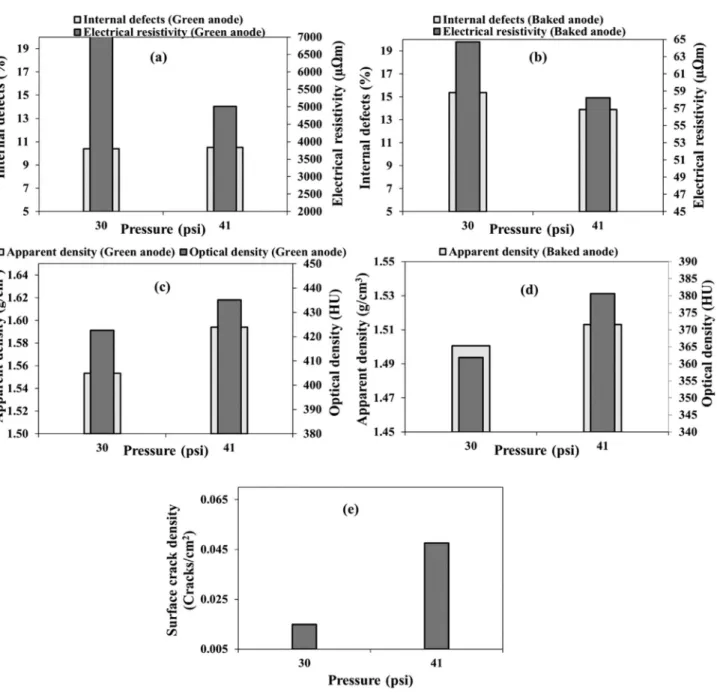
3.3.2 Top‑former bellow pressure
Two anodes (anodes 3 and 8) were made using a top-former bellow pressure of 41 and 30 psi (Table 3). The electrical resistivity decreased as the pressure increased both for green and baked anodes (Fig. 7a and b). Under-compaction (in this case, due to an insufficient pressure) led to poor anode quality. Less pitch penetrated between the particles and in the particle pores, increasing the elec-trical resistivity. The percentage of internal defects for the two green anodes were similar (Fig. 7a) whereas those of the baked anodes were clearly different. The baked anode manufactured with the low compaction pressure had more internal defects than that manufactured using a higher pressure. Under-compaction makes the matrix weak and facilitates the formation of pores and cracks (Fig. 7b). If the anode has more defects, its electrical resis-tivity also increases as pores and cracks form a barrier to the passage of an electric current (discontinuous solid medium).
As expected, the anode manufactured under a low compaction pressure has a lower density (both apparent and optical) than the anode manufactured at the higher compaction pressure (Fig. 7c and d). The baked anode compacted at higher pressure had more surface cracks which did not again reflect the overall quality of the anode (Fig. 7e).
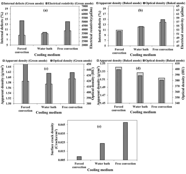
3.4 Green anode cooling medium
Three green anodes (anodes 3, 9 and 10, Table 3), which were produced under the same conditions, were cooled differently: free convection in air, forced convection in air, and forced convection in a water bath. Cooling was stopped when the measured temperature reached the temperature of the cooling medium. The percentage of internal defects was the lowest for the anode cooled by forced convection in air and the highest for the one cooled by free convection in air both for green and baked anodes. The electrical resistivity was lowest when the anode was cooled by immersing in water bath for green anodes, and the resistivities of the green anodes cooled with forced and free convection in air were similar. The resistivity of a green anode is generally influenced by pores/defects as well as by pitch distribution. Non-carbonized pitch has a high electrical resistivity. If there are high pitch regions, an increase in resistivity occurs in those regions [3, 26]. Also, the cooling rate is lower in air, which leads to a more porous anode due to the spring-back effect. For baked anodes, the resistivity and the number of internal defects
were the lowest for the anode cooled by forced convection in air and the highest for the one cooled by free convection in air (Fig. 8a and b). In addition, the apparent and optical densities of baked anodes, which were cooled using forced convection in air after green anode is formed, were the highest. For the green anode, the apparent density was highest for the anode cooled with free convection in air whereas the optical density was highest for the anode cooled with forced convection in air. The presence of impurities in the raw material could also affect the optical density (Fig. 8c and d). The surface cracks were also lowest for the anode cooled with forced convection in air (Fig. 8e). In general, the results indicate that the forced convection in air seems to be the best option for cooling green anodes among the three options tested in this study. It must be noted that there are other parameters that need to be studied such as water and air temperatures, air flow rate for the forced convection, combination of water/air cool-ing media, etc. before the most suitable coolcool-ing medium could be selected.
3.5 Heating rate used during baking
Eight anodes, four without butts (anodes 14, 15, 16, and 17) and four containing butts (anodes 3, 11, 12, and 13), were baked using low (7 °C/h), medium (11 °C/h), high (15 °C/h), and combination (15–7–15 °C/h) heating rates (Table 3). Concerning the combination heating rate, after initially using a high heating rate at low temperatures, a low heating rate was used during the pitch devolatili-zation period since most of the cracks form during this period. The rest of the baking was carried out at the high-est heating rate. Baking time depends on the heating rate used. Usually, the lowest heating rate is the best since the volatiles are released slowly during pitch carbonization, and this prevents the formation of high internal pressure in the anode during volatile release and consequently reduces the cracks formation [30]. However, this increases the anode production time and cost, and decreases the production rate. The combination heating rate scheme was proposed since the baking during the critical period was carried out at a low heating rate without increasing the total production time compared to that of standard heating rate (medium) (Table 3).
3.5.1 Anodes without butts
The electrical resistivities and apparent densities of the anodes before baking (green anodes) are given in Fig. 9a and c. As it can be seen from these figures, there are some differences in these properties of the green anodes although they are produced under the same condi-tions. This is expected since the anode raw materials are
non-homogeneous, resulting in small differences in prop-erties. The effect of heating rate on the internal cracks and electrical resistivity are presented in Fig. 9b whereas their effect on the apparent and optical densities are given in Fig. 9d for baked anodes. Figure 9e presents the surface crack density of the baked anodes.
The results show that the internal defect percent-age and electrical resistivity of anodes baked at the lowest and combination heating rates are similar and lower than those of the anodes baked using medium and high heating rates. In addition, the anodes baked at
the lowest and combination heating rates have higher apparent and optical densities than the other two anodes baked at medium and high heating rates. The surface crack density also decreased with decreasing heating rate and the anode baked at the combination heating rate had a similar surface crack density to the anode baked at the lowest heating rate (Fig. 9e). It seems that the better-quality anodes are produced using the lowest and combination heating rates; however, it must be noted that their corresponding green anodes had better quality before baking. Therefore, more testing is
Fig. 8 Effect of cooling medium on: a–b internal defect percentage and electrical resistivity, c–d apparent and optical densities, and e
needed to confirm the positive impact of low heating rate on anode quality.
3.5.2 Anodes with butts
Four other anodes, this time with the butt addition, were produced and baked using the four heating rates explained in the previous section. The properties of green anodes used are given in Fig. 10 a and c. The heating rates shown in these figures indicate the heating rate used when these green anodes were baked. It is difficult to make
green anodes with the same properties due to the non-homogeneity of the raw materials. Although, the green anode, which was later baked using the combination heat-ing rate, had the highest internal crack before bakheat-ing, the corresponding baked anode had the lowest internal cracks among the anodes tested (Fig. 10b). In addition, this anode also had high anode apparent and optical densities after baking even if it had lower green anode densities com-pared to that of the green anode baked at the lowest heat-ing rate and similar to that of the green anode baked at the medium heating rate (Fig. 10b). The anode baked with the
Fig. 9 Effect of heating rate on: a electrical resistivity, b internal
defect percentage and electrical resistivity, c apparent density, d apparent and optical densities, and e surface crack density in a,
c green anodes baked later with shown heating rates and b, d, e
combination heating rate also had the lowest resistivity. As it can be seen from the Fig. 10a and b, although the anode baked at the medium heating rate had similar electrical resistivity to those baked using the low and combination heating rates in green state, it had higher resistivity after baking when compared to those of the same anodes in baked state. The properties of the anode baked using the combination heating rate were similar to those baked at the lowest heating rate. Its surface crack density was also the lowest (Fig. 10e). After, these tests, it now possible to state that the lowest and combination heating rates give
better quality anodes. The combination heating rate has the advantages of shorter production time (similar to that baked at medium heating rate, which is the average heat-ing rate usually observed in industry) compared to the anode produced using the low heating rate.
3.6 Correlation between anode properties and anode quality
The Fig. 11a and b show the effect of internal defect (cracks/pores) percentage on the electrical resistivity for
Fig. 10 Effect of heating rate on: a electrical resistivity, b internal
defect percentage and electrical resistivity, c apparent density, d apparent and optical densities, and e surface crack density in a,
c green anodes baked later with shown heating rates and b, d, e
green and baked anodes, respectively. Electrical resistivity increased as the internal defect percentage increased for both anodes. This means that the anode quality decreases with increasing internal defects since higher resistivity indicates higher energy consumption to produce the
same quantity of aluminum. The high resistivity indicates the presence of pore/cracks as well as the local high pitch regions in green anodes since pitch has high resistivity before carbonization (baking); and the high resistivity is due to defects/pores in baked anodes.
Fig. 11 Correlation between a–b electrical resistivity, c–d optical density, and e–f apparent density and internal defect percentage:
Similarly, it can be seen from the optical and appar-ent density vs. internal defect percappar-entage data that the anode density, hence the anode quality, decreased with increasing internal defects both for green (Fig. 11c and d) and baked anodes (Fig. 11e and f ). This is in agree-ment with the resistivity data. These results show the tendencies expected with respect to the relation between various parameters.
4 Conclusions
The quality of anode is related to the internal defects since anode properties are affected by the presence of pores and cracks. In this study, the effect of differ-ent anode production parameters on anode proper-ties (electrical resistivity, optical and apparent densi-ties) were studied. Increasing pore/crack percentage decreases anode density and increases electrical resis-tivity. Lower anode density results in shorter anode life (lower production and higher gas emissions per unit carbon used) whereas lower anode resistivity indicates greater power consumption and higher cost per unit alu-minum produced. Therefore, it is crucial to know where on the production line these defects are formed and take the necessary precautions to prevent their formation as much as possible.
The results showed that raw materials significantly affect the anode quality. Using high butt percentage increases the defects. It is important to use enough pitch. Over and under-pitching the anodes increase the internal defects. Process parameters such as vibro-compaction time, the top-former bellow pressure used during compac-tion, and the type of media used to cool the green anodes were studied. The compaction parameters should be as close to their optimum values as possible since over and under-compaction of green anodes result in defect forma-tion. Cooling anodes with forced convection in air gave the best quality green anodes under the conditions studied.
Baking is one of the most important steps in anode pro-duction which plays an important role in defining the final anode quality. If the baking conditions are not chosen well, even the best quality green anode might result in a poor quality-baked anode. One of the important baking param-eters is the heating rate. This study showed that the anode quality is better if the anodes are baked at a low heating rate. However, in practice, the utilization of low heating rate reduces the production and increases the cost. Most of the cracks form during the devolatilization period while the pitch is carbonizing. If the heating rate is high, high quantity of volatiles are released in a short time interval. This increases the pressure inside the anode causing crack-ing. When the heating rate is low, the volatiles are release
slowly over a longer period of time. In this case, the crack formation is reduced due to lower internal pressure build-up inside the anode. Therefore, a combination heating rate was proposed to produce good quality anodes without increasing the production rate and cost. In combination heating rate, it is recommended to use a low heating rate during the devolatilization period and high heating rate at other times. The application of such a heating rate vari-ation as a function of the temperature range in the plant will require the reconsideration of the furnace control and testing on site.
Acknowledgements The technical and financial support of
Alumin-erie Alouette Inc. as well as the financial support of the Natural Sci-ences and Engineering Research Council of Canada (NSERC), Dével-opment économique Sept-Îles (DESI), the University of Québec at Chicoutimi (UQAC), and the Foundation of the University of Québec at Chicoutimi (FUQAC) is greatly appreciated.
Funding This study was funded by Natural Sciences and Engineering
Research Council of Canada (NSERC) in collaboration with Alumin-erie Alouette Inc. (AAI), Dévelopment économique Sept-Îles (DESI), the University of Québec at Chicoutimi (UQAC), and the Foundation of the University of Québec at Chicoutimi (FUQAC) (Grant num-ber: RDCPJ 417499–11) in the frame of the Program “Collaborative Research and Development”.
Complaince with ethical standards
Conflict of interest The authors declare that they have no financial
interest and no conflict of interest.
Open Access This article is licensed under a Creative Commons
Attri-bution 4.0 International License, which permits use, sharing, adap-tation, distribution and reproduction in any medium or format, as long as you give appropriate credit to the original author(s) and the source, provide a link to the Creative Commons licence, and indicate if changes were made. The images or other third party material in this article are included in the article’s Creative Commons licence, unless indicated otherwise in a credit line to the material. If material is not included in the article’s Creative Commons licence and your intended use is not permitted by statutory regulation or exceeds the permitted use, you will need to obtain permission directly from the copyright holder. To view a copy of this licence, visit http://creat iveco mmons .org/licen ses/by/4.0/.
References
1. Lustenberger M (2004) Heat treatment of carbon anodes for the aluminium industry. Ph.D. Dissertation, École Polytech-nique Fédérale de Lausanne, Switzerland
2. Sarkar A, Kocaefe D, Kocaefe Y, Bhattacharyay D, Morais B, Cou-lombe P (2016) Effect of coke granulometry on the proper-ties of carbon anodes based on experimental study and ANN analysis. JMSR 5(4):63–78. https ://doi.org/10.5539/jmsr.v5n4p 63
3. Hulse KL (2000) Anode manufacture: raw materials, formulation and processing parameters. R&D Carbon, Sierre Switzerland
4. Meier MW (1996) Cracking behaviour of anodes. R&D Carbon, Sierre Switzerland
5. Ahoutou Y (2017) Détermination du niveau de brai dans une anode crue par analyse d’images. Master Thesis, University of Quebec at Chicoutimi
6. Bureau J, Kocaefe D, Bhattacharyay D, Kocaefe Y, Morrais B (2016) Quantification of sodium present in dry aggregates and anodes. Light Metals. https ://doi.org/10.1007/978-3-319-48251 -4_148 7. Sarkar A, Kocaefe D, Kocaefe Y, Bhattacharyay D, Sarkar D,
Morais B, Chabot J (2014) Coke-pitch interactions during anode preparation. Fuel 117A:598–607. https ://doi.org/10.1016/j. fuel.2013.09.015
8. Figueiredo FEO, Kato CR, Nascimento AS, Marques AOF, Miotto P (2005) Finer fines in anode formulation. Light Metals. Springer, Cham, pp 665–668
9. Tkac M (2007) Porosity Development in Composite Carbon Materials during Heat Treatment. Norwegian University of Sci-ence and Technology, Dissertaion
10. Farr-Wharton R, Welch BJ, Hannah RC, Dorin R, Gardner HJ (1980) Chemical and electrochemical oxidation of heterogene-ous carbon anodes. Electrochim Acta 25(2):217–221. https ://doi. org/10.1016/0013-4686(80)80046 -6
11. Yi S, Huai G, Shanhong Z, Chaodong L, Haifei X (2013) Compari-son of mixing process methods in prebaked anode production. Light Metals. https ://doi.org/10.1007/978-3-319-65136 -1_191 12. Pérez SP, Doval-Gandoy J, Ferro A, Silvestre F (2005) Quality
improvement for anode paste used in electrolytic production of aluminium. in Conference Record - IAS Annual Meeting (IEEE Industry Applications Society)
13. Dorcheh KA (2013) Investigation of the materials and paste relationships to improve forming process and anode quality. Dissertation. Canada, Laval University
14. Rebain F (2015) Étude de l’influence des paramètres de vibro-compaction sur les propriétés mecaniques des anodes crues en carbone. Dissertation. Chicoutimi, University of Quebec 15. Jonathan PH, Arnaud B, Sonia T (2011) Maximising vibroformer
performance through vibration monitoring. 10th Australasian Aluminium Smelting Technology Conference, Launceston, Tas., Australia
16. Sanogo B (2017) Détection de la fin de la compaction des anodes par le son. Master Thesis, University of Quebec at Chicoutimi
17. Charette A, Kocaefe S, Kocaefe D (2012) Le carbone dans l’industrie de l’aluminium. Les presses de l’aluminium (PRAL). 32(1):57
18. Jarry M (1977) Elaboration des anodes précuites en carbone aggloméré pour l’industrie de l’aluminium. Dissertation, Uni-versité Scientifique et Médicale de Grenoble, France
19. Fischer WK, Keller F, Perruchoud RC, Oderbolz S (2016) Baking parameters and the resulting anode quality. In: Tomsett A, John-son J (eds) Essential readings in light metals. Springer, Cham, pp 427–433. https ://doi.org/10.1007/978-3-319-48200 -2_59 20. Severo S, Gusberti V, Sulger PO, Keller F, Meier MW (2011) Recent
developments in anode baking furnace design. Light Metals. https ://doi.org/10.1007/978-3-319-48160 -9_146
21. Bain, GA, Pruneau JP, Williams J (1971) The effect of prebaked anode baking temperature in potroom performance. Light Met-als, 444–449. https ://doi.org/10.1007/978-3-319-48200 -2_61 22. Killer F, Mannweiler U, Knall E (2007) Construction and operating
anode plants: What top management needs to know, Anode for Aluminum Industry. R&D Carbon, 4th ed, Sierre Switzerland 23. Sendid S, Courau A (2014) High performance of “Eolios”
pitch fume treatment system. Light Metals. https ://doi. org/10.1007/978-3-319-48144 -9_193
24. Kocaefe D, Bhattacharyay D, Kocaefe Y (2019) Method for analyz-ing an anode and device thereof. Patent US 10(281):421 25. Kocaefe Y, Kocaefe D, Bhattacharyay D (2015) Quality control
via electrical resistivity measurement of industrial anodes. Light Metals. https ://doi.org/10.1007/978-3-319-48248 -4_184 26. Amrani S (2015) Impact de la préparation des anodes crues et
des conditions de cuisson sur la fissuration dans des anodes denses. Dissertation. Chicoutimi, University of Quebec 27. Amrani S, Kocaefe D, Kocaefe Y, Bhattacharyay D, Bouazara M,
Coulombe P (2017) Evolution of anode properties during bak-ing. IJISET 4(4):2348–7968
28. Xie Y, Kocaefe D, Kocaefe Y, Wei L, Zou S, Wu A (2013) Correlation between anode recipe and anode properties. International Jour-nal of Engineering and Innovative Technology (IJEIT) 2(8):23–27 29. Lu, Y (2016) Effect of pitch properties on anode properties,
Mas-ter Thesis, University of of Quebec at Chicoutimi
30. Wilkening S (2013) Properties and behaviour of green anodes. Essential readings in Light Metals. https ://doi.org/10.1007/978-3-319-48200 -2_49
Publisher’s Note Springer Nature remains neutral with regard to