is an open access repository that collects the work of Arts et Métiers Institute of
Technology researchers and makes it freely available over the web where possible.
This is an author-deposited version published in: https://sam.ensam.eu Handle ID: .http://hdl.handle.net/10985/14556
To cite this version :
Mario BERMUDEZ GUZMAN, Oleg GOMOZOV, Xavier KESTELYN, Federico BARRERO, Ngac Ky NGUYEN, Eric SEMAIL - Model predictive optimal control considering current and voltage limitations: Real-time validation using OPAL-RT technologies and five-phase permanent magnet synchronous machines - Mathematics and Computers in Simulation - Vol. 158, p.148-161 - 2019
Any correspondence concerning this service should be sent to the repository Administrator : [email protected]
Model predictive optimal control considering current and voltage
limitations: Real-time validation using OPAL-RT technologies and
five-phase permanent magnet synchronous machines
M. Bermudez
a,b*, O. Gomozov
a, X. Kestelyn
a, F. Barrero
b, N.K. Nguyen
a, E. Semail
a aUniv. Lille, Arts et Metiers ParisTech, Centrale Lille, HEI, EA 2697 – L2EP – Laboratoire d’Electrotechnique et d’Electronique de Puissance,F-59000, Lille, France.
bDepartamento de Ingeniería Electrónica, Universidad de Sevilla, Camino de los Descubrimientos s/n, 41092, Sevilla, Spain
Abstract
Multiphase machines have recently gained interest in the research community for their use in applications where high power density, wide speed range and fault-tolerant capabilities are required. The optimal control of such drives requires the consideration of voltage and current limits imposed by the power converter and the machine. While conventional three-phase drives have been extensively analyzed taking into account such limits, the same cannot be said in the multiphase drives’ case. This paper deals with this issue, where a novel two-stage Model Predictive optimal Control (2S-MPC) technique is presented, and a five-phase permanent magnet synchronous multiphase machine (PMSM) is used as a case example. The proposed method first applies a Continuous-Control-Set Model Predictive Control (CCS-MPC) stage to obtain the optimal real-time stator current reference for given DC-link voltage and stator current limits, exploiting the maximum performance characteristics of the multiphase drive. Then, a Finite-Control-Set Model Predictive Control (FCS-MPC) stage is utilized to generate the switching state in the power converter and force the stator current tracking. An experimental validation of the proposed controller is finally provided using a real-time simulation environment based on OPAL-RT technologies.
Keywords: Multiphase drives; Model predictive control; Current and voltage limits; Optimal reference currents; Real-time simulation
environments
1. Introduction
The interest in recent times in multiphase drives relies on their fault-tolerance inherent capabilities and on the ability to manage the power with lower torque pulsation and lower current harmonic content than conventional three-phase ones [2,5,13], which usually reduce the electrical stresses on the machine and the power electronic components. Such advantages make them ideal candidates for applications where electrical limits are normally reached, becoming the reliability a key control issue for economical and safety reasons when multiphase drives are considered. For example, high-speed operation in traction and power generation applications using multiphase drives are typically required, while it is also desirable to extract the maximum torque capability over the entire speed range. These control requirements will depend on the voltage and current limits of the multiphase machine and the voltage source inverter (VSI), making essential the application of optimal control methods that take into account such limits or constraints.
While optimal controllers are mature control techniques in conventional three-phase drives, this is not the case and the situation becomes much more complicated when multiphase systems are considered. One dq reference frame appears in three-phase drives, which simplifies the definition of the analytical expressions of the optimal stator current reference while respecting the imposed constraints. The machine flux is usually weakened (the d-current stator component is reduced) to respect the imposed voltage limit, adjusting at the same time the q-current stator component with the aim of not exceeding the current limit. Many algorithms have been proposed in the scientific literature based on this flux-weakening control idea for induction [8,23] and permanent magnet [12] machines. However, when
* Corresponding author.
E-mail addresses: [email protected] (M. Bermudez), [email protected] (O. Gomozov), [email protected]
multiphase drives are considered, permanent magnet and concentrated windings induction machines have been analyzed in [20,22,24], where the torque density is increased adding a third spatial harmonic in the magnetic field, but the operation in the field weakening region under electrical limits has not been studied. This absence of scientific analyses for the multiphase case relies on the appearance of multiple orthogonal dq spaces, where the optimization problem becomes quite complex and makes difficult to find analytical expressions for the reference stator currents in the different dq reference sets. Indeed, the phase peak value of the electrical magnitude depends on the peak value of each harmonic but also on their respective phase shifts. Therefore, some simplifications are normally assumed to get analytical expressions for the reference values when limits are considered. This is the case in [14,19], where it is assumed that all harmonics components reach their peak values at the same time instant and suboptimal results are obtained. A different alternative appears in recent research works, where the optimal current references are based on offline procedures that generate look-up tables [6,17]. These works also consider the steady state operation of the drive, and do not take into account the electrical and mechanical dynamics of the real system. Then, there is a need for new research works and methodologies to find optimal reference values when multiphase systems with current and voltage limits are considered.
A potential solution to the optimization problem can be the application of the Model Predictive Control (MPC) technique. This control strategy offers a high flexibility facing multi-input multi-output systems subject to constraints. The method is based on an accurate model of the system that it is used to predict the future behavior of the system through time, in order to select the optimal value of the control variables by minimizing a predefined cost function [4]. MPC techniques can be categorized into two major types: Continuous-Control-Set MPC or CCS-MPC, where an average model of the system is defined and controlled with the purpose of generating continuous reference signals; and Finite-Control-Set MPC or FCS-MPC, which takes advantage of the limited number of switching states available in the VSI for solving the optimization problem using an iterative algorithm. It is noteworthy that MPC techniques have been widely utilized to solve control problems in electrical applications with power converters [4]. Different control objectives and/or restrictions are easily included, and MPC has been employed for controlling multiphase drives giving a high flexibility [1,16,21]. Nevertheless, none of these proposals takes into account electrical limits for the drive in the control strategy, up to the authors’ knowledge. In [9], these limits have been barely considered to obtain optimal reference currents using classical PI regulators to guarantee the current tracking, while the present work goes beyond all mentioned proposals, stating that optimal reference currents can be obtained using model-based predictive methods. The main objective of the paper is then to introduce a new multiphase MPC method, named as two-stage Model-based Predictive optimal Control (2S-MPC). The proposed controller generates online optimal current references by means of a CCS-MPC stage that respects imposed voltage and current limits. Then, a control stage based on a FCS-MPC method is applied for the current regulation of the system. The achievements of the 2S-MPC technique compared to classical methods can be summarized as follows:
The proposed controller allows the consideration of electrical restrictions in the regulator strategy, including voltage and current limits imposed by the power converter and the electrical machine. An important industrial demand, in relation with obtaining the higher requirements in the peak torque and power density of modern motor drives, is then attended because an increment in the reliability levels of the drive is forced introducing stringent controllers with the ability of managing failure mechanisms and critical electrical limits.
The modulation stage using an inner current controller based on the FCS-MPC method can be suppressed, which improves the close-loop torque performance providing faster torque transient [15,16]. Note also that the tuning of the controller is practically effortless, in contrast to that of PI-PWM based methods.
Although optimal controllers have been previously stated in the research bibliography, only suboptimal solutions have been raised up in the multiphase drives’ field. In this particular research area, some simplifications and/or assumptions were considered in the control strategy to take into account the considered electrical limits as stated before. However, the proposed method permits the online computation of the optimal current reference, ensuring the optimality condition of the problem.
A performance analysis of the controller is also done prior to the application to a real system. A real-time simulation environment based on the OPAL-RT technology is selected for this purpose, in order to accelerate the analysis, to reduce risks associated with conducting tests on a physical system and to simplify its future
implementation [3].The paper is organized as follows. First, Section 2 analyzes the five-phase PMSM drive as well
Section 4 details the implementation of the 2S-MPC method in the real-time system, providing the validation results that show the closed-loop performance of the multiphase drive working with the considered limits. Finally, conclusions are presented in Section 5.
2. Presentation of the studied system
2.1. Modeling of the five-phase PMSM drive
The system under study is based on a five-phase star-coupled PMSM, supplied by a five-phase two-level VSI. A simplified scheme of the drive is shown in Fig. 1. The voltage, flux and torque equations of the drive are normally obtained considering the following assumptions:
Some effects like magnetic saturation, hysteresis and iron losses are neglected. Only first and third harmonics of periodical variables are considered.
Slot effects are assumed to be negligible.
Taking this into account, the stator voltage equation is given by:
e t i L Ri v d d (1) ia va -+
S
bS
a A BS
aS
b VDC 2 VDC 2 N N’ ib vb -+ ic vc -+S
dS
c C DS
cS
d id vd -+S
e ES
e ie ve -+Fig. 1. Schematic diagram of the five-phase PMSM drive.
where R is the stator resistance, i and e are the stator current and back-EMF vectors, respectively, and L is the inductance matrix.
The existing magnetic coupling between phase windings makes difficult the control of the five-phase machine in the phase frame. A coordinate transformation is normally applied to reduce this complexity, which converts the phase variables into two independent rotating reference frames, called dq1 and dq3. It is possible to link a two-phase fictitious machine to each dq subspace, as it is presented in [11]. The first (second) fictitious machine is called the main (secondary) machine, modeled in the dq1 (dq3) subspace and associated with the fundamental (third harmonic) of the real machine variables. The coordinate transformation is done by the extended Park transformation matrix detailed in (2), producing new voltage equations presented in (3)-(6). Note that this transformation will generate constant dq1 and dq3 components in steady state.
2 1 2 1 2 1 2 1 2 1 5 2 3 sin 5 4 3 sin 5 4 3 sin 5 2 3 sin 3 sin 5 2 3 cos 5 4 3 cos 5 4 3 cos 5 2 3 cos 3 cos 5 2 sin 5 4 sin 5 4 sin 5 2 sin sin 5 2 cos 5 4 cos 5 4 cos 5 2 cos cos p p p p p p p p p p p p p p p p p p p p 5 2 P (2) 1 1 1 1 1 1 d d q q d d d d p L i t i L Ri v (3) 1 1 1 1 1 1 1 2 5 d d f d d q q q q p L i t i L Ri v (4) 3 3 3 3 3 3 3 d d q q d d d d p L i t i L Ri v (5) 3 3 3 3 3 3 3 2 5 3 d d f d d q q q q p L i t i L Ri v (6) where: vd1, vq1, id1, iq1 and vd3, vq3, id3, iq3 are the projections of the phase voltages and currents in the subspaces dq1 and
dq3, respectively.
Ld1, Lq1, Ld3, Lq3 are the inductances along the d and q axes associated with the first and third harmonics of the air gap flux.
p is the number of pole pairs.
Φf1 and Φf3 are the fluxes along the d axis created by the permanent magnets associated with the first and third harmonics of the air gap flux, respectively.
Following this approach, the electromagnetic torque of the real machine is determined as the sum of the torques developed by both fictitious machines, as it is stated down below:
3 1 em em em T T T (7)
1 1 1 1 1 1 1 2 5 q f q d q d em p L L i i i T (8)
3 3 3 3 3 3 3 2 5 3 d q d q f q em p L L i i i T (9)2.2. Considered constraints
From the physical point of view, maximizing the torque capability of the multiphase drive depends on the voltage and current constraints of the machine and the VSI. The voltage limit comes from the maximum DC-link voltage that the VSI can apply to the machine (maximum peak phase-to-phase voltage, VDC), and it is obtained in the flux-weakening region, where the available torque decreases when the machine operates above the base speed. On the other hand, current limits are imposed by: the power converter and its electronic switches, which limit a maximum
peak phase current value (IVSI); and the copper losses in the machine, which generate a maximum RMS phase current
(IRMS). For the sake of simplicity, it is considered in this work that the RMS phase current never exceeds the maximum available value and safety margins are included for controllability reasons for the maximum peak phase current value and the maximum peak phase-to-phase voltage (Imax and Vmax, respectively). Then, the electrical constraints that will be taken into account in what follows are summarized as:
max VSI phaset I I i (10)
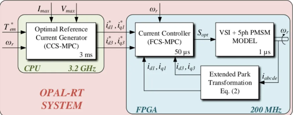
max DC phase to phase t V V v (11) 3. Proposed 2S-MPC techniqueThe scheme of the proposed 2S-MPC method is shown in Fig. 2, where the two main stages are identified. The optimization problem (first control stage) is a reference current generator based on CCS-MPC that finds the best way to divide currents between d and q axes. It can be considered as an extra part of the inner current controller (second control stage), where the FCS-MPC method is used for the stator current regulation. An outer PI-based speed control loop should be also considered to implement a variable speed drive based on the utilization of a multiphase electric machine. However, the study is focused on the performance of the multiphase drive when online optimal reference currents are applied to get the reference torque, while minimizing the copper losses and respecting the defined maximum peaks values of currents and voltages. Then, the analysis is done in the open-loop torque regulation configuration to avoid any interference of the outer speed controller in the electrical performance of the system. Notice that a machine simulator stage is plotted (see next section) to identify that we are not using an experimental test rig but a real-time simulation environment based on OPAL-RT technologies for modeling the multiphase drive.
Sopt ωr T em* Vmax Imax Current Controller (FCS-MPC) Extended Park Transformation Eq. (2) iq3 id3, iq1 id1, i* d1,iq1* id3* i * q3 , CPU 3.2 GHz
OPAL-RT
SYSTEM
50 µs VSI + 5ph PMSM MODEL 1 µs ωr iabcde FPGA 200 MHz Optimal Reference Current Generator (CCS-MPC) 3 ms ωrFig. 2. Proposed 2S-MPC technique for a five-phase PMSM.
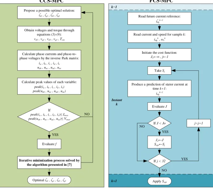
(9). -(3) equations respecting and , , , , , , , : * 2 3 2 3 2 1 2 1 max ae ad ac ab max e d c b a 2 em em T q d q d i V u u u u peak I i i i i i peak to subject T T i i i i f min (12)where two weighting factors ωi and ωT are introduced in the objective function f to give more or less importance to the minimization of the copper losses with respect to the reference torque tracking. In this case, the multiphase drive has been analyzed using a steady state model of the system and a simulation environment based on Matlab© tools. It is concluded that ωi = 1 and ωT = 10000 are appropriate values to guarantee a good tracking of the reference torque when the drive operates inside the feasible reference region (i.e. below the maximum torque versus speed characteristic of the electrical machine) and the production of the maximum possible torque when the reference current is not feasible and the operating point is outside the feasible region. The procedure to solve the optimization problem is summarized in Fig. 3 (left plot), where the model of the multiphase drive described in equations (3)-(9) is required. The model is discretized using a forward Euler method and used with a possible dq current optimal reference to obtain reference dq voltage and torque values that can be applied to the machine. Then, phase currents and phase-to-phase voltages are calculated from previous dq current and voltage values, using the inverse of the Park transformation matrix detailed in (2). After that, the peak values of these variables are extracted to verify if the constraints are respected, and if this is the case, the objective function is also evaluated for the proposed solution (dq current references) and the generated torque. If the constraints are not respected, a new possible dq current optimal reference is analyzed in the same way, and the process starts over. This optimization problem is rewritten in the standard form of a quadratic programming problem and solved in an iterative manner by the algorithm presented in [7].
On the other hand, the FCS-MPC method is utilized as an inner predictive stator current controller. It is based on
the discretization of the five-phase PMSM model, which is used along with the measured speed ωrk and the stator
currents idqk in the time instant k to obtain the future stator current values in the next sampling period k+1 (idqk+1). The predictive model is based on dq transformation and it is discretized employing the forward Euler integration method. The control objective of the predictive current controller lies on defining a cost function J and finding the switch configuration to be applied in the VSI (Sopt). This optimum value Sopt is obtained computing the predictive model for every available switching state (25 = 32 for our five-phase machine) to predict the future stator current and find the
one that minimizes J. The cost function considered in this work consists in tracking the optimal current references that were calculated in the previous stage, as it is shown in (13). This second optimization process is detailed in the flow diagram shown in the right plot of Fig. 3.
2 k q k q 2 k d k d 2 k q k q 2 k d k d i i i i i i i i J * 1 3 1 3 1 3 1 * 3 1 1 1 * 1 1 1 1 * 1 (13)
To summarize, the optimization problem that leads to the optimal current references is convex and thus it has only one optimal solution without local minima, checking the optimality condition and providing the optimal reference to the FCS-MPC controller. Then, the FCS-MPC stage uses a finite set of switching states, checking all of them to apply the optimal one that minimizes the designed cost function. Notice that a one-step prediction horizon is used in this study. Although better results are expected with longer prediction horizons, a bigger online calculation effort would be required and a prediction horizon equal to one should be enough to state the interest of the proposal. Note also that the optimization problem is adapted to a continuous physical system with a time constant higher than 1 ms, while the second stage is adjusted to the finite state and switching nature of the power converter.
Initiate the cost function: Jo←∞ , j←1 Take Sj If J < Jo Jo←J Sopt←Sj j=j+1 Evaluate J NO YES
Produce a prediction of stator current at time k+1:
Read future current reference:
Instant k k−1
Read current and speed for sample k:
idq k+1
FCS-MPC
idq k , ω r k k+1 If j < 32 YES Apply Sopt NO idq* k+1 Evaluate fCCS-MPC
YES NO Obtain voltages and torque throughequations (3)-(9):
vd1 , vq1 , vd3 , vq3 , Tem
Calculate phase currents and phase-to-phase voltages by the inverse Park matrix:
ia , ib , ic , id , ie uab , uac , uad , uae
Calculate peak values of each variable:
peak(ia , ib , ic , id , ie) peak(uab , uac , uad , uae)
If
peak(ia , ib , ic , id , ie)≤ Im ax peak(uab , uac , uad , uae)≤ Vmax
Iterative minimization process solved by the algorithm presented in [7]
Optimal id1 , iq1 , id3 , iq3
* * * *
Propose a possible optimal solution:
* * * *
id1 , iq1 , id3 , iq3
Fig. 3. Description of the optimization processes in CCS-MPC (left plot) and FCS-MPC (right plot) stages.
4. Validation of the 2S-MPC technique in a real-time system based on OPAL-RT technologies
To validate the 2S-MPC proposed method, an experimental set-up system is programed in a real-time system based on the OP5600 real-time simulator target platform complemented with the OP5607 extension module from OPAL-RT technologies. The Xilinx Virtex 7 FPGA of the OP5607 module is used for building the machine simulator and the FCS-MPC current controller, using an internal clock frequency of 200 MHz. On the other hand, the Intel Xeon CPU of the OP5600 platform is used to communicate with a host PC and to solve the optimal references generation, sending the obtained results to the FPGA as well as the reference inputs (such as the reference torque and speed). The CPU performance allows up to 3 ms of sampling time for the optimal reference currents generator for single core mode, although further improvements could be obtained by parallelizing the solver. Notice however that the switching frequency is limited in real applications by the switching losses in the IGBT modules of the power converter. Then,
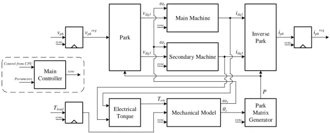
Tload sync Main Machine Secondary Machine Inverse Park Park Mechanical Model Park Matrix Generator Electrical Torque Main Controller vdq1 vdq3 idq3 idq1 ωr sync Tem θr P iph iphreg vph vphreg Pa rameters Control from CPU
sync sync sync sync sync sync ωr ωr
Fig. 4. General architecture of the five-phase PMSM real-time model simulator in FPGA.
the frequency of the FCS-MPC is set to 20 kHz due to this limitation, although the obtained frequency is higher. The obtained margin is used in our case to reduce the resource use in the FPGA by further pipelining the mathematical operations in the predictor of the FCS-MPC controller.
Focusing on the machine simulator, it is running in the FPGA at 1 MHz with 1 µs of sampling time. The model of the machine is discretized using the forward Euler method since it is the easiest discretization process to be implemented. It also provides sufficient stability and precision for the used simulation time step (1 µs), which is much smaller than the smallest time constant of the machine. The inputs of the model are the mechanical load torque, phase voltages (or inverter switch configuration) and the DC-link voltage. The outputs are stator voltage and current values in both dq and phase frames, along with the electrical torque and the speed of the machine. They are connected to four analog outputs of the OPAL-RT simulator and can be configured from the CPU part of the simulator.
The simulation model is split into multiple interconnected computation cores, which are responsible for various parts of the model. The general architecture of the FPGA implementation is shown in Fig. 4. The model is managed using a main controller that it is configured and supervised by the CPU part of the OPAL-RT simulator. Its main function is to generate synchronization signals, controlling the data flows between computation cores and insuring simulation synchronization with its time step. Other computation cores are: park transformation, fictitious machines, torque estimator and mechanical model of the machine’s rotor. The states of the simulation model are stored inside the corresponding cores and include the Park matrix, currents in dq frame, the electrical torque, and the speed and position of the rotor, respectively.
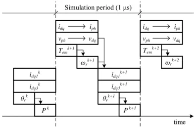
The computations are done in parallel and controlled through the synchronization signals. The timeline is shown in Fig. 5. First, the input voltages are converted from phase to dq frame (vph —› vdq) and the previous state currents from dq to phase frame (idq —› iph), by using the Park matrix stored in the registers of its generator (Pk). Additionally, the new electrical torque (Temk+1) and speed (ωrk+1) are computed based on previous states of the model. Once the new speed is available, the new rotor position can be found (θrk+1) and the Park matrix can be updated (Pk+1). When both new speed and dq voltages are ready, new currents in main and secondary fictitious machines can be calculated in parallel (idq1k+1 and idq3 k+1, respectively), and a new simulation step can begin.
Since the Park matrix depends on the position of the rotor, each simulation step is generated using two look-up tables containing the values for sines and cosines, and it is stored in double registers. The Park matrix generator structure is shown in Fig. 6, where the sequencer is controlled by the external synchronization signal and iteratively populates the registers of the Park matrix using one of the look-up table and the corresponding electrical angle θe. Once the registers have been all written, they are stored in a second register array in such a way that the Park matrix changes instantly for the external cores. This approach allows to reduce the resource use in FPGA, taking advantage of the computation time of other cores of the model.
The main computation of the simulation occurs in the fictitious machines cores, based on dq frame. The equations for both fictitious machines are independent and can be simulated in parallel. For example, consider the equations (3)
P k P k+1 θrk idq1 k idq3k idq1 k+1 idq3k+1 Temk+1 ωr k+1 θrk+1 Simulation period (1 μs) ωrk+2 Temk+2 idq iph vph vdq idq iph vph vdq time Fig. 5. Simulation model computation timeline.
ROM sin Sequencer θr P sync Preg sync 2π 5 + 4π 5 + 4π 5 -2π 5 -p θe sel0 sel1 en ROM cos
Fig. 6. Park matrix generator.
and (4), which represent the voltages of the main machine. These equations are rewritten in the ordinary first order differential equation form, as follows:
1 1 1 1
1 1 d d q q d d d d v Ri p L i L 1 t i (14) 1 1 1 1 1 1 1 2 5 1 d d f d d q q q q i L p Ri v L t i (15)Then, new values for the currents are calculated at each simulation step using the following equations:
( ) ( ) ( ) ( )
) ( ) 1 ( 1 1 1 1 1 1 1 v k Ri k p k L i k L h k i k i d d q q d d d (16) 1 1 1 1 1 1 1 1 2 5 ) ( ) ( ) ( ) ( ) ( ) 1 ( q q d d f q q q v k Ri k p k L i k L h k i k i (17)
being h a simulation step used for the modeling. The discretized equations for the secondary machine can be obtained in a similar way. Summarizing, the equations for both fictitious machines can be written as follows:
) ( ) ( ) ( ) ( ) 1 (k k1i k k2v k k3 k i k id d d q (18)
6 7
5 4 ( ) ( ) ( ) ( ) ) 1 (k k i k k v k k k i k k iq q q d (19)where coefficients k1 to k7 are parameters of the model and vary for each fictitious machine. These calculations define the core of the simulation and are implemented as a pipelined architecture. The previous values for the currents in dq frame are stored in registers controlled by the external synchronization signal and updated every simulation step.
Different tests have been carried out to validate the proposed 2S-MPC, using the machine parameters and limits detailed in Table 1 as well as the aforementioned real-time system. First, the ability of the 2S-MPC technique to generate optimal current references while respecting the limits over the entire speed range (from zero to the limit speed of the machine) is analyzed, summarizing Fig. 7 the obtained results. Figs. 8 and 9 complement this analysis, showing the steady state operation of the system in different operating points that include the operation without electrical limits, considering one current or voltage limit and with the application of both limits. The dynamic behavior of 2S-MPC is also verified, and Fig. 10 summarizes the obtained results. In this case, the multiphase machine is operated outside the feasible region to focus on the operation of the system when the voltage and current limits are applied.
The first set of tests includes the steady state analysis of the controlled system in different operating points. A speed ramp is imposed to the machine from 0 rad/s to the limit speed of 240 rad/s, while the reference torque is always set higher than the maximum value (19.27 N-m, see Table 1), making that the peak value of phase currents is equal to the established limit (50 A) during the whole test. The maximum torque versus speed characteristic of the electrical machine is then obtained, once the steady state operation of the system is reached, as it is shown in Fig. 7a (blue ink). Figure 7a also illustrates the considered case studies, when the electrical limits are not reached (reference points in region 1 or case 1), if the current limit must be applied (reference points in region 2 or case 2), if the voltage limit is considered (reference points in region 3 or case 3), and taking into account the voltage and current constraints (reference points in region 4 or case 4). The evolution of dq1 and dq3 currents is also plotted (see Fig. 7b), showing the steady state performance of the system depending on the operating point. Notice that below the base speed (100 rad/s), the voltage limit is never reached, therefore obtained id1 and id3 values are equal to zero and the machine is not in the flux-weakening region. Furthermore, iq1 is always positive in order to produce a positive electrical torque when the fundamental of the flux is applied, but iq3 (which represents the third harmonic component of the stator current) is negative to guarantee that the maximum peak value for the phase current is not exceeded at the price of generating a negative electrical torque in the system. Once the base speed is reached, id1 and id3 currents become negative in order to comply with the voltage limit. It is important to note that the machine is now operating in the well-known flux-weakening region and the system is also regulated in our case optimizing the third harmonic current components,
id3 and iq3 values, to be respectful with the established limits. The present analysis shows that the 2S-MPC method manages the system taking into account the limits and following the real-time established optimization problem (a desired torque is generated considering the copper losses produced in the system in order to minimize them).
The previous analysis is complemented in Figs. 8 and 9, where the steady state performance of the system in four different case studies (corresponding with the cases illustrated in Fig. 7a) is analyzed. These reference points are detailed in Table 2, where the applied reference torque and speed are shown. The evolution of the phase current is plotted in Figs. 8a and 9a in order to see if the current limit is reached in the analyzed cases. Notice that only one phase (phase ‘a’) is shown for the sake of clarity, but similar results are obtained for the rest of the stator current phases, from ‘b’ to ‘e’. Figs. 8b and 9b depict all filtered phase-to-phase voltages to find out that the voltage limits
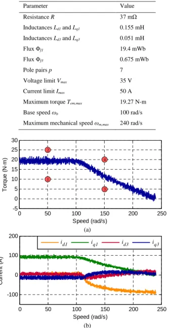
Parameter Value Resistance R 37 mΩ Inductances Ld1 and Lq1 0.155 mH Inductances Ld3 and Lq3 0.051 mH Flux Φf1 19.4 mWb Flux Φf3 0.675 mWb Pole pairs p 7
Voltage limit Vmax 35 V Current limit Imax 50 A Maximum torque Tem,max 19.27 N-m Base speed ωb 100 rad/s Maximum mechanical speed ωm,max 240 rad/s
0 50 100 150 200 250 -100 0 100 200 Speed (rad/s) C u rr e n t (A ) id1 iq1 id3 iq3 (a) (b) 0 50 100 150 200 250 -5 0 5 10 15 20 25 30 Speed (rad/s) T o rq u e ( N ·m ) 1 2 3 4
Fig. 7. Steady state analysis of the multiphase drive system, including a speed ramp test where the speed is varied in the machine from 0 rad/s to 240 rad/s and the reference torque is higher than the maximum value. (a) Obtained electrical torque versus speed characteristic of the system. (b)
Evolution of dq1 and dq3 stator current values.
are regulated. When the machine operates and the established limits are not reached (case 1, Fig. 8a, left plot), it is observed that the obtained phase current using the optimal references from the 2S-MPC method (orange ink) is quite similar to the one corresponding with the analytical solution (green ink) that is found imposing the analytical optimal
dq reference currents from the copper losses point of view [10]:
0 * dk i (20) * 3 , 1 2 * em i qi qk qk T i
(21)Table 2. Analyzed steady state reference points in Figs. 8 and 9. Case Operation Reference torque Speed 1 Below the limits 10 N-m 50 rad/s 2 Under current limit 25 N-m 50 rad/s 3 Under voltage limit 5 N-m 150 rad/s 4 Under current and voltage limit 20 N-m 150 rad/s
0 0.005 0.01 0.015 0.02 0.025 0.03 0.035 -40 -20 0 20 40 60 Time (s) V o lt a g e ( V ) u ab uac uad uae 0 0.005 0.01 0.015 0.02 0.025 0.03 0.035 -40 -20 0 20 40 60 Time (s) V o lt a g e ( V ) u ab uac uad uae 0 0.005 0.01 0.015 0.02 0.025 0.03 0.035 -100 -50 0 50 100 Time (s) C u rr e n t (A )
ia , sim ulation ia , analytical
0 0.005 0.01 0.015 0.02 0.025 0.03 0.035 -100 -50 0 50 100 Time (s) C u rr e n t (A ) ia (a) (b)
Case 1: Below the limits Case 2: Under current limit
Fig. 8. Steady state operation in cases 1 and 2: operation without considering voltage or current limits (left plots) and considering the current limit (right plots). (a) Stator phase current. (b) Filtered phase-to-phase stator voltages.
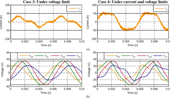
0 0.002 0.004 0.006 0.008 0.01 -40 -20 0 20 40 60 Time (s) V o lt a g e ( V ) u ab uac uad uae 0 0.002 0.004 0.006 0.008 0.01 -40 -20 0 20 40 60 Time (s) V o lt a g e ( V ) u ab uac uad uae 0 0.002 0.004 0.006 0.008 0.01 -100 -50 0 50 100 Time (s) C u rr e n t (A ) ia 0 0.002 0.004 0.006 0.008 0.01 -100 -50 0 50 100 Time (s) C u rr e n t (A ) ia (a) (b)
Case 3: Under voltage limit Case 4: Under current and voltage limits
Fig. 9. Steady state operation in cases 3 and 4: operation considering a voltage limit (left plots) and taking into account current and voltage limits (right plots). (a) Stator phase current. (b) Filtered phase-to-phase stator voltages.
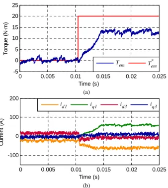
0 0.005 0.01 0.015 0.02 0.025 -100 0 100 200 Time (s) C u rr e n t (A ) id1 iq1 id3 iq3 0 0.005 0.01 0.015 0.02 0.025 -5 0 5 10 15 20 25 Time (s) T o rq u e ( N ·m ) Tem T*em (a) (b)
Fig. 10. Dynamic response of the controlled system using the proposed 2S-MPC technique under current and voltage limits. The reference torque is changed from 0 to 20 N-m (at t = 0.01 s approximately), while the machine is operated at 150 rad/s (above the base speed). (a) Torque
response. (b) Evolution in dq1 and dq3 stator currents.
being εqk the speed-normalized back-EMF. This result verifies a good similarity between the proposed 2S-MPC technique and the analytical optimal solution if the constrains are not reached. In all the other cases, the current and voltage limits are considered and regulated by the proposed 2S-MPC technique, although the obtained current cannot be compared with any analytical optimal solution up to the authors’ knowledge. Obtained results prove the reliability of the 2S-MPC method, which complies the voltage and current limitations in every case study.
Finally, the dynamic operation of the system using the proposed controller is analyzed imposing a reference torque step from 0 to 20 N-m (at t = 0.01 s approximately) while the machine is regulated at 150 rad/s during the whole test (the system is working over the base speed operating point). It is important to note that this reference point (20 N-m and 150 rad/s) is clearly out of the feasible region of the machine. The obtained torque response is shown in Fig. 10a, where the generated torque cannot achieve the reference. This is an expected performance because the reference point is out of the maximum torque versus speed characteristic of the machine. The obtained torque is about 12 N-m, which corresponds with the maximum available torque that the machine can produce operating at 150 rad/s (see Fig. 7a). On the other hand, the evolution of dq1 and dq3 currents is depicted in Fig. 10b. The machine is in the flux-weakened region during the whole experiment: id1 and id3 currents are not zero, being optimally adapted in real-time to respect the voltage limit. Meanwhile, iq1 and iq3 currents are zero before t = 0.01 s because no generated torque is required. Once the reference torque step is applied, iq1 and iq3 currents become positive to maximize the produced torque while respecting the current limit. It is shown again that the obtained reference currents using the 2S-MPC technique are appropriate and the proposed controller is viable. It is interesting to highlight that the obtained results do not consider the parameter uncertainty of the system, which is out of the scope of this work. Parameter uncertainty is a complex research field in electromechanical systems when model-based predictive controllers are used [18], but also when conventional PI-PWM control techniques are applied, where the estimation of the rotor flux position is mandatory.
5. Conclusion
This paper introduces a novel two-stage MPC technique, or simply 2S-MPC method, to generate online optimal reference currents and the maximum electrical torque in a close-loop controlled multiphase machine when current
and voltage constrains are considered in the control strategy. It fills a gap in the scientific literature, where only suboptimal solutions have been raised, normally making some simplifications or assumptions to obtain the analytical expressions for the current references when current and voltage limits are considered. The implementation of the technique in a real-time simulation environment based on OPAL-RT technologies is used to validate the effectiveness of the proposal in steady and transient state operating conditions, where optimal reference currents are generated and the system is close-loop controlled.
Acknowledgements
The authors would like to acknowledge the doctoral school of ENSAM and the “Ministerio de Economía y Competitividad” of the Spanish Government under reference DPI2016-76144-R for the financial support of this work.
References
[1] M. R. Arahal, F. Barrero, S. Toral, M. J. Duran, R. Gregor, Multiphase current control using finite-state model-predictive control, Control Eng. Pract. 17 (5) (2009) 579–587.
[2] F. Barrero, M. Duran, Recent advances in the design, modeling and control of multiphase machines – Part 1, IEEE Trans. Ind. Electron. 63 (1) (2016) 449–458.
[3] J. Bélanger, P. Venne, J.N. Paquin, The what, where and why of real-time simulation, Planet RT 1 (1) (2010), 25–29.
[4] P. Cortes, M.P. Kazmierkowski, R.M. Kennel, D.E. Quevedo, J. Rodriguez, Predictive control in power electronics and drives, IEEE Trans. Ind. Electron. 55 (12) (2008) 4312–4324.
[5] M. Duran, F. Barrero, Recent advances in the design, modeling and control of multiphase machines – Part 2, IEEE Trans. Ind. Electron. 63 (1) (2016) 459–468.
[6] O. Fall, N.K. Nguyen, J.F. Charpentier, P. Letellier, E. Semail, X. Kestelyn, Variable speed control of a 5-phase permanent magnet synchronous generator including voltage and current limits in healthy and open-circuited modes, Electr. Pow. Syst. Res. 140 (2016) 507– 516.
[7] O. Gomozov, J.P. Trovao, X. Kestelyn, M. Dubois, Adaptive energy management system based on a real-time model predictive control with non-uniform sampling time for multiple energy storage electric vehicle, IEEE Trans. Veh. Technol. 66 (7) (2017) 5520–5530.
[8] L. Harnefors, K. Pietilainen, L. Gertmar, Torque-maximizing field-weakening control: design, analysis, and parameter selection, IEEE Trans. Ind. Electron. 48 (1) (2001) 161–168.
[9] X. Kestelyn, O. Gomozov, J. Buire, F. Colas, N.K. Nguyen, E. Semail, Investigation on model predictive control of a five-phase permanent magnet synchronous machine under voltage and current limits, in: IEEE International Conference on Industrial Technology, Seville, Spain, 2015, pp. 2281–2287.
[10] X. Kestelyn, E. Semail, A vectorial approach for generation of optimal current references for multiphase permanent-magnet synchronous machines in real time, IEEE Trans. Ind. Electron. 58 (11) (2011) 5057–5065.
[11] X. Kestelyn, E. Semail, J.P. Hautier, Vectorial multi-machine modeling for a five-phase machine, in: International Conference on Electrical Machines (ICEM), Bruges, 2002, CD-ROM, Paper 394.
[12] J.M. Kim, S.K. Sul, Speed control of interior permanent magnet synchronous motor drive for the flux weakening operation, IEEE Trans. Ind. Appl. 33 (1) (1997) 43–48.
[13] E. Levi, Advances in converter control and innovative exploitation of additional degrees of freedom for multiphase machines, IEEE Trans. Ind. Electron. 63 (1) (2016) 433–445.
[14] E. Levi, D. Dujic, M. Jones, G. Grandi, Analytical determination of DC-bus utilization limits in multiphase VSI supplied AC drives, IEEE Trans. Energy Convers. 23 (2) (2008) 433–443.
[15] C.S. Lim, E. Levi, M. Jones, N.A. Rahim, W.P. Hew. A comparative study of synchronous current control schemes based on FCS-MPC and PI-PWM for a two-motor three-phase drive, IEEE Trans. Ind. Elect. 61 (8) (2014) 3867–3878.
[16] C.S. Lim, N.A. Rahim, W.P. Hew, E. Levi, Model predictive control of a two-motor drive with five-leg-inverter supply, IEEE Trans. Ind. Electron. 60 (1) (2013) 54–65.
[17] L. Lu, B. Aslan, L. Kobylanski, P. Sandulescu, F. Meinguet, X. Kestelyn, E. Semail, Computation of optimal current references for flux-weakening of multi-phase synchronous machines, in: Proc. 38th Annual Conference of the IEEE Industrial Electronics Society, Montreal, Canada, 2012, pp. 3610–3615.
[18] C. Martín, M. Bermúdez, F. Barrero, M.R. Arahal, X. Kestely, M.J. Durán, Sensitivity of predictive controllers to parameter variation in five-phase induction motor drives, Control Eng. Pract. 68 (2017) 23–31.
[19] M. Mengoni, L. Zarri, A. Tani, L. Parsa, G. Serra, D. Casadei, High-torque-density control of multiphase induction motor drives operating over a wide speed range, IEEE Trans. Ind. Electron. 62 (2) (2015) 814–825.
[20] L. Parsa, H.A. Toliyat, Five-phase permanent-magnet motor drives, IEEE Trans. Ind. Appl. 41 (1) (2005) 30–37.
[21] J. Rodriguez, M.P. Kazmierkowski, J.R. Espinoza, P. Zanchetta, H. Abu-Rub, H.A. Young, C.A. Rojas, State of the art of finite control set model predictive control in power electronics, IEEE Trans. Ind. Informat. 9 (2) (2013) 1003–1016.
[22] J. Wang, R. Qu, L. Zhou, Dual-rotor multiphase permanent magnet machine with harmonic injection to enhance torque density, IEEE Trans. Appl. Supercond. 22 (3) (2012) 5202204–5202204.
[23] X. Xu, D.W. Novotny, Selection of the flux reference for induction machine drives in the field weakening region, IEEE Trans. Ind. Appl. 28 (6) (1992) 1353–1358.
[24] H. Xu, H.A. Toliyat, L.J.Petersen, Five-phase induction motor drives with DSP-based control system, IEEE Trans. Power Electron. 17 (4) (2002) 524–533.