Science Arts & Métiers (SAM)
is an open access repository that collects the work of Arts et Métiers Institute of
Technology researchers and makes it freely available over the web where possible.
This is an author-deposited version published in:
https://sam.ensam.eu
Handle ID: .
http://hdl.handle.net/10985/18384
To cite this version :
Damien THUAU, Konstantinos KALLITSIS, Sara HA, François BARGAIN, Thibaut SOULESTIN,
Gilles PÉCASTAINGS, Sylvie TENCÉ-GIRAULT, Fabrice DOMINGUES-DOS SANTOS, Georges
P. HADZIIOANNOU - High and Temperature-Independent Dielectric Constant Dielectrics from
PVDF-Based Terpolymer and Copolymer Blends - Advanced Electronic Materials - Vol. 6, n°3,
p.1-9 - 2020
Any correspondence concerning this service should be sent to the repository
Administrator :
archiveouverte@ensam.eu
High and Temperature-Independent Dielectric Constant
Dielectrics from PVDF-Based Terpolymer and Copolymer
Blends
Damien Thuau,* Konstantinos Kallitsis, Sara Ha, François Bargain, Thibaut Soulestin,
Gilles Pecastaings, Sylvie Tencé-Girault, Fabrice Domingues Dos Santos,
and Georges Hadziioannou*
1. Introduction
Polymer dielectrics are attracting increasing interest in organic electronics and in particular to be applied as gate die-lectrics thin films for flexible organic field effect transistors (OFETs).[1–4] The key
fea-tures of a low power consumption OFET lie on its insulating properties providing low gate leakage current, high dielectric breakdown voltage, and high dielectric constant. In order to decrease the oper-ating voltage of OFETs, it is necessary to make a gate dielectric layer with high permittivity (k) materials and/or having a reduced film thickness. Since downscaling polymer gate dielectric thickness below 100 nm without drastically increasing the gate leakage current is extremely chal-lenging, efforts have been focused on the development of high-k materials as gate dielectric thin films.[5–7] Despite the
fact that most polymer insulators have a low dielectric constant (≈3), other poly-mers with polar groups of strong dipole moments in their molecular chains usu-ally exhibit higher dielectric permittivity
Relaxor ferroelectric polymers exhibit high k at their structural phase transition around room temperature. They are particularly attractive as gate dielectric in organic field effect transistor (OFET). Nevertheless, their applications are limited due to their low thermal stability. A polymer blend system with a high and thermally stable dielectric constant is dem-onstrated by mixing terpolymer poly(vinylidene fluoride-trifluoroethylene-chlorofluorethylene) P(VDF-ter-TrFE-ter-CFE) with copolymer poly(vinylidene
fluoride-trifluoroethylene) P(VDF-co-TrFE). PVDF-based blends of various
compositions are characterized by dielectric spectroscopy, differential scan-ning calorimetry (DSC), infrared spectroscopy, small and wide angle X-ray scattering (SAXS and WAXS), and atomic force microscopy (AFM) in order to investigate the relationship between morphology and crystallization of the blend and their dielectric properties. An optimized blend of P(VDF- ter-TrFE-ter-CFE) [55/37/8] and P(VDF-co-TrFE) [46/54] at a ratio of 70/30 is found to
exhibit a quasi-constant dielectric constant of 40 ± 2 over a wide temperature range (20–80 °C). Furthermore, electrical characteristics of the PVDF-blend-based gate dielectric OFET show further thermal stability in comparison to OFET based on high-k terpolymer P(VDF-ter-TrFE-ter-CFE) [55/37/8]. An
improvement of their drain current stability by up to 60% is demonstrated at 60 °C. These findings enable broader applications of fluoropolymers in organic electronics. Dr. D. Thuau Univ. Bordeaux CNRS Bordeaux INP IMS
UMR 5218, F-33607 Pessac, France E-mail: damien.thuau@ims-bordeaux.fr
Dr. K. Kallitsis, S. Ha, G. Pecastaings, Prof. G. Hadziioannou Univ. Bordeaux
CNRS Bordeaux INP LCPO
UMR 5629, F-33615 Pessac, France E-mail: georges.Hadziioannou@enscbp.fr
Dr. F. Bargain, Dr. S. Tencé-Girault Arkema
CERDATO
Route du Rilsan, 27470 Serquigny, France Dr. T. Soulestin, Dr. F. Domingues Dos Santos ARKEMA-Piezotech
Rue Henri-Moissan, 69493 Pierre-Benite Cedex, France Dr. S. Tencé-Girault
PIMM
Arts et Metiers Institute of Technology CNRS
Cnam
HESAM University
compared to the non-polar ones. Among them, poly(vinylidene difluoride) (PVDF) and its derivatives PVDF-based copolymers and terpolymers obtained by introducing trifluoroethylene (TrFE), chlorotrifluoroethylene (CTFE), and chlorofluoroeth-ylene (CFE) monomers into the (VDF) chains exhibit excellent dielectric and electric properties.[8] PVDF-based ferroelectric
polymers found numerous applications in modern flexible electronics.[9] While ferroelectric P(VDF-co-TrFE) has been
employed as gate dielectric for non-volatile-memories-based OFETs,[10,11] terpolymer poly(vinylidene
fluoride-trifluoroeth-ylene-chlorofluorethylene) P(VDF-ter-TrFE-ter-CFE), a ferroelec-tric relaxor exhibiting high-k (≈60) at room temperature was also successfully integrated as gate dielectric layer for low operating voltage OFETs.[12,13] Nevertheless, these fluorinated polymers
were chosen for their high-k at their structural phase transition with the attendant disadvantage that temperature dependence is important, thus drastically impacting the electrical character-istics of transistors even under small temperature variations. In this work, we present an approach to tackle the critical issue of temperature dependence of the dielectric constant of
P(VDF-ter-TrFE-ter-CFE) by mixing different fluorinated copolymers
and terpolymers. Polymer blends that possess the features of both polymers offer a great opportunity to improve or tailor the properties of the initial polymer. To date, blends of fluorinated polymers have been reported in the past to tailor the ferroelec-tric properties of the films and improve electrocaloric effect, breakdown strength, and energy density.[14–18] Ullah et al.
inves-tigated blend system of P(VDF-co-TrFE) and P(VDF-ter-TrFE-ter-CFE) and obtained a blend containing 60 wt% of terpolymer with improved energy density of about 4.2 J cm−3 in contrast
to about 3.6 J cm−3 in the terpolymer under an electric field of 125 MV m−1.[14] Zhang et al. reported an enhancement of
electric breakdown strength in PVDF/P(VDF-ter-TrFE-ter-CFE) blends compared with neat polymers as well as an ultrahigh energy density of 19.6 J cm−3 achieved at the composition of 60/40 vol% (PVDF/terpolymer).[16] Similarly, Chu et al.
demon-strated that blending of ter-TrFE-ter-CFE) and
P(VDF-co-CTFE) improves the breakdown fields and dielectric energy
density of the blend system (25 J cm−3 at 600 MV m−1), which are crucial to applications requiring capacitors with high energy density and good reliability under high electric field.[17] The
crystallization behavior of fluorinated polymer blends of PVDF/ P(VDF-co-TrFE) and P(VDF-co-TrFE)/P(VDF-ter-TrFE-ter-CFE) and the impact on their corresponding electroactive properties were also investigated.[19,20] Here, we aim to demonstrate a high
and quasi-constant dielectric constant polymer (40 ± 2) over the range of temperature 20–80 °C, which is one of the most prom-inent requirements for improved reliability of electronics.
2. High and Temperature Independent Dielectric
Constant Polymer
PVDF-based terpolymers have been extensively used as high-k gate dielectrics in OFET due to their good dielectric properties. However, the structural phase transition of P(VDF-ter-TrFE-ter-CFE) around room temperature results in temperature-sensitive dielectric properties and a serious decrease in permittivity at higher temperature.[21,22] To improve the temperature stability
of P(VDF-ter-TrFE-ter-CFE) material, we present an effective approach by blending different compositions of fluorinated polymers to achieve high and constant dielectric constant at temperature ranging from 20 to 80 °C. Depending on the com-position of the blend, their dielectric properties can be tuned accordingly in the range of copolymer to terpolymer properties. Consequently, we demonstrate that an appropriate selection (ratio, material composition) of terpolymers and copolymer can lead to a high and thermally stable dielectric constant over the temperature range 20–80 °C.
First, we characterized the dielectric constant, εr, of pristine
copolymer co-TrFE) 46/54 and terpolymers
P(VDF-ter-TrFE-ter-CFE) of different compositions. The temperature
dependence of the dielectric constant was measured at 1 kHz as shown in Figure 1a. All measurements were performed on metal–insulator–metal devices using aluminum (Al) as bottom and top electrodes. P(VDF-co-TrFE) copolymer con-taining 54 mol% of TrFE unit has a maximum relative per-mittivity peak at a temperature of 66 °C and do not depict any thermal hysteresis between heating and cooling, as it is usu-ally observed for the Curie transition.[23,24] These features are
markers of a defective ferroelectric phase (DFE)[23] and is in
agreement with the phase diagram reported by Tashiro et al. where copolymer containing VDF amount lower than 55% do not exhibit hysteresis.[24] For this composition range,
relaxor-ferroelectric (RFE) behavior was reported by Liu et al., once again no thermal hysteresis is observed.[25] Figure 1a shows
also the dielectric spectroscopy characterization of P(VDF-ter-TrFE-ter-CFE) terpolymers containing 7 and 8 mol% of CFE unit and named, respectively, Terpo-7 and Terpo-8. As expected, Terpo-8 exhibit a maximum relative permittivity at lower tem-perature in regards to Terpo-7. Subsequently, blends of terpoly-mers and copolyterpoly-mers were prepared with the aim of achieving dielectric materials with high and temperature independent relative permittivity. Figure 1b,c represents the relative permit-tivity of blend of Terpo-7 and Terpo-8, respectively, with various amount of copolymer Copo-46/54, while their dielectric losses are shown in Figure S1, Supporting Information. Increasing amount of copolymer in the blends from 5% to 30% shifts the peak of dielectric constant of the terpolymer to higher tem-perature. From these measurements, it can be seen that low amount of copolymer (below 10%) slightly increases the max-imum value of dielectric constant of the blend exceeding the initial high k value of P(VDF-ter-TrFE-ter-CFE) terpolymer. As shown in Figure 1b, a blend film composed of 90% of Terpo-7 and 10% of Copo-46/54 exhibits a maximum dielectric constant of 51. Further addition of copolymer in the blend was found to decrease the dielectric constant as shown in Figure 1b,c regard-less the composition of the terpolymer. More interestingly, an appropriate mixing ratio between terpolymer and copolymer was observed to flatten the dielectric constant of the blend over the temperature range 20–80 °C for both Terpo-7 and Terpo-8. Blends of 70/30 ratios of terpolymer, Terpo-7 or Terpo-8, and copolymer depict a quasi-constant and relatively high value of relative permittivity of 36 ± 3 and 40 ± 2, respectively. With the aim of realizing transistor with low operating voltages ther-mally stable, a high and constant permittivity in a wide temper-ature range is necessary. Consequently, the following section of the paper focused only on the blend containing Terpo-8.
Relative permittivity, εr′, depends on the crystallinity and is
maximum at the crystal–crystal transitions from the relaxor-ferroelectric (RFE) to the paraelectric (PE) phases or from the ferroelectric (FE) to the paraelectric (PE) phases.[21] It is worth
mentioning that the difficulty to modelize the shape of εr′ for
a blend of two semi-crystalline polymers.[26] Indeed, the blend
can be viewed as a superposition of crystalline and amorphous domains from each constituents with strong interfacial effects. As working hypothesis, we can assume that the flattening of εr′
is the result of a phase separation between crystalline domains from Terpo-8 and Copo-46/54, each crystalline domains under-going their proper crystal–crystal transition with temperature. To further investigate the origin of this εr′ plateau, we
per-formed a detailed structural study.
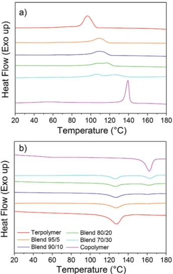
Differential scanning calorimetry (DSC) was employed to investigate the effect that blending has on the crystallinity of the polymers. To do so, the thermograms of the terpolymer–copol-ymer blends were compared to the pristine terpolterpolymer–copol-ymer and copolymer, respectively. It was observed that during the cooling ramp (after the first melting, not shown in Figure 2), the crys-tallization peaks of the two components of the blend appear shifted at intermediate temperatures between the crystallization temperatures of the pristine polymers (Figure 2a) indicating that the one component of the blend impacts the crystallization of the other. Whereas during the heating ramp (Figure 2b), the melting peaks of the copolymer and the terpolymer appeared unchanged in the blend indicating that the crystal structure and the crystal size are not significantly modified. Concretely, the
Figure 1. Dielectric spectroscopy: relative permittivity as a function of
temperature measured at 1 kHz of a) copolymer P(VDF-co-TrFE) taining 54% of TrFE unit; and terpolymer P(VDF-ter-TrFE-ter-CFE) con-taining 7 and 8 mol% of CFE unit; b) blends of Terpo-7 and Copo-46/54 at different ratios; c) blends of Terpo-8 and Copo-46/54 at different ratio.
Figure 2. DSC thermograms of Terpo-8, Copo-46/54, and their blends
at different ratios 95/5, 90/10, 80/20, and 70/30 during a) first cooling, b) second heating.
blends containing 20% and 30% of copolymer show two dis-tinct peaks which indicate they do not co-crystallize. Neverthe-less, for blend systems containing 5% and 10% of Copo-46/54, one can observe the presence of a single crystallization (and melting) peak which may be interpreted by a certain miscibility of both components’ chains that affect the crystallization of the blend. On the one hand, the shift of the copolymer crystalliza-tion comes from the delay required by the copolymer chain to expel the terpolymer chain before crystallization. This behavior is similar to the blend system PVDF/PMMA-based diblock copolymer.[27] On the other hand, when the mixing system is
partially crystallized by means of the copolymer chains, the number of interfaces can serve as a nucleus, accelerating the crystallization of the terpolymer chains. The corresponding enthalpies were measured in each case for the melting and crystallization transitions (Table 1). From the measured melting enthalpies, it appears that increasing the copolymer content in the blend, the total crystallinity slightly decreases, despite the copolymer itself (ΔH = 29 J g−1) being more crystalline than the
terpolymer (ΔH = 20 J g−1). We attribute the decrease of
crys-tallinity in blends to the partial miscibility of the copoly mer and terpolymer chains, which slows down the kinetics of crystallization.
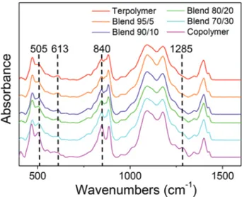
Chain conformations associated with the crystalline phases in copolymer P(VDF-co-TrFE) and terpolymer P(VDF-ter-TrFE-ter-CFE) are not the same.[28] These conformations are characterized
by specific bands in Fourier transform infrared spectroscopy (FTIR). FTIR experiments were performed on films of the pris-tine terpolymer and copolymer as well as all their blends and the spectra are presented in Figure 3. The introduction of the copolymer in the blends leads to the increase in intensity of the bands at 505, 840, and 1285 cm−1 which are correlated to β phase of PVDF.[29,30] On the other hand, the intensity of the
band at 613 cm−1 corresponding to a specific band of the PVDF α phase[29,30] steadily decreases with increasing the copolymer
content in the blend. Bands assigned to the PVDF β phase are characteristic of the all-trans conformations while the band of the α phase reveals the existence of tg+ tg− conformations.
WAXS spectra were recorded for each polymers and blends to measure the impact of blending on the crystalline structure and crystallinity. The relaxor ferroelectric crystalline phase (RFE) was identified in Terpo-8, with an interplanar distance of 4.91,
(Figure 4a), while the defective ferroelectric (DFE) and the fer-roelectric (FE) phases were found in Copo-46/54 with distances 4.78 and 4.65 Å, respectively (Figure 4b). These phases are iden-tified in agreement with previous works.[21,24] In all the blends,
we observe the coexistence of these crystalline phases RFE, DFE, and FE with various amount depending of the composition of the blend (Figure 4c). From the decomposition of the WAXS spectra in amorphous broad peaks and sharp crystalline peaks, we can deduce the ratio of each crystalline phase and the total weight crystallinity. The evolutions of these values with the com-position of the blend are reported in Figure 4d. In blends, the RFE amount is always lower than the linear model expected values, while DFE and FE amount are higher than the expected values. For all the blends, the crystallinity remains as low as in Terpo-8 (21%), lower than that in Copo-46/54 (31%), only the 70/30 blend has an intermediate crystallinity of about 24%.
The morphology of the films was evaluated from AFM height and phase images (see Figure 5). AFM images reveal various nanostructured surfaces of the films with grain, rod-like or even fibers that are tangled up as a ball of wool. Height and phase AFM scans of Terpo-8 and blend 95/5 depicted a similar morphology where long (>1 µm) and thin (<60 nm) fibers organized in a spherical shape from nucleation point can be observed. On the contrary, AFM scans of P(VDF-co-TrFE) showed a completely different morphology with small grains of average dimension about 70–80 nm long and ≈50 nm wide. The blend systems containing copolymer content of 10, 20, and 30 wt% showed a morphology with grains whose average lengths were 203 ± 40, 112 ± 30, and 173 ± 40 nm, respec-tively. The content of P(VDF-co-TrFE) did not show significant effect of the width of the grain with an average grain width of 58 ± 10 nm. On each of those grains, periodic black lines were observed with a favorable orientation parallel to the length of the grains, probably crystalline lamellae. The average distance between two adjacent black lines were measured to be 13.8, 16.9, and 15.7 nm for the following blend systems 90/10, 80/20, and 70/30.
SAXS acquisitions simultaneously recorded with WAXS complete this morphological study. All of the SAXS spectra
Table 1. Crystallization and melting temperatures of Terpo-8,
Copo-46/54, and the different blends with their associated enthalpy. Crystallization Melting
Tonset [°C] Enthalpy [J g−1] Tmend [°C] Enthalpy [J g−1]
Terpolymer 108 20 138 20 Blend 95/5 122 20 140–170 17 (16 + 1) Blend 90/10 123 19 141–170 18 (17 + 1) Blend 80/20 129 19 140–172 14 (10 + 4) Blend 70/30 140 21 134–172 16 (9 + 7) Copolymer 147 29 170 29
For the blends two melting endotherms are observed, their two melting tem-peratures and their two enthalpies (in bracket) are reported as well as the total enthalpy.
in Figure 6 show a high intensity at low q, with sometimes a well-defined maximum, this small angle scattering could be attributed to the shape of the objects viewed with AFM. The well-defined maximum observed for Copo-46/54, Terpo-8, and the blends 95/5 and 90/10 correspond to a size between 60 and 80 nm, this dimension should be the width of the fibers (Terpo-8 and Blend-95/5) or of the long grains (Copo-46/54 and Blend-90/10). For the other samples, the anisotropy of the object is less marked, the length and width becoming compa-rable, their respective diffusions are no longer separated, no well-define peak is observed, only a broad scattering. The other maximum correspond to distances between 20 and 37 nm.
These dimensions fit well the period of crystalline lamellae observed in this kind of copolymers after annealing.[21,23] The
sharpest peaks are observed in the Blend-90/10 (19 and 32 nm) and in Blend-80/20 (22 and 37 nm). For the Blend-70/30, broader peaks would appear shifted toward lower q, assigned to higher distance than for 80/20. It is difficult to interpret these peaks because in blends there is the coexistence of two crystalline domains, RFE and DFE/FE, and we do not know if these phases are organized in the same crystalline lamellae or in separated crystalline lamellae. The experiments performed here cannot answer this question. We cannot conclude on the signification of the black lines observed on AFM pictures for
Figure 4. WAXS spectra of a) Terpo-8, b) Copo-46/54, c) Blend 70/30 with the decomposition in amorphous phase in grey, RFE phase in orange, DFE
phase in red, and FE phase in blue. Zoom around the main peak is represented in a), b), and c) with the detail of the decomposition; d) crystalline phase ratio for RFE (⚫), DFE (▴), and FE (◻) phases, the dashed-dotted lines represent the linear evolution from 0 to 100%; the weight crystallinity (▸).
Figure 5. AFM images of height and phase of fluorinated polymer blend films at different terpolymer/copolymer ratios (100/0, 95/5, 90/10, 80/20,
the blends 90/10, 80/20, 70/30 and for the copolymer. Indeed, the distance between these black lines does not evolve with the composition of the blends and no black lines are observed in terpolymer and Blend-95/5.
From this structural study, we conclude that in the various terpolymer and copolymer blends, the crystalline structures RFE and DFE/FE, specific of relaxor ferroelectric and of fer-roelectric polymers are observed and coexist. From DSC and WAXS, we deduce that the proportion of RFE crystalline phase is lower than the amount of terpolymer in the blend, and inversely, the proportion of DFE/FE crystalline phase is higher than the amount of copolymer. We conclude that we have a good mixing of the chains of each constituent followed by a redistribution of the chains in the two types of crystalline phases. Probably the two crystalline transitions RFE to PE and DFE/FE to PE (Curie transition) exist in the blends with two distinct temperatures. A maximum of the dielectric constant is expected for each crystal–crystal transition. The plateau observed in Figure 1 would be due to the succession of the two structural transitions in temperature, and therefore to the juxta-position of the two maximum of εr′.
3. Thermally Stable OFET
Flexible P(VDF-ter-TrFE-ter-CFE) based transistors can lead to new advances in biomedical engineering, wearable electronics, and soft robotics. However, their lack of thermal stability due to their low phase transition temperature represents their main drawback. The conception of thermally stable OFETs requires that both the semiconductor and the gate dielectrics layers retain their electrical characteristics over an operating tempera-ture range. Among organic semiconductors,
dinaphtho[2,3-b:2′,3′-f]thieno[3,2-b]thiophene (DNTT) was often chosen for the conception of heat resistant OFET owing to its good thermal stability. Associated to an inorganic thin layer of AlOx[31,32] or
combined with self-assembled monolayer (SAM),[33]
DNTT-based OFETs showed no significant degradation in their elec-trical characteristics at temperature below 150 °C. Pentacene combined with a thermally stable polymer, polyimide, has also been reported to stand operating temperature as high as 160 °C.[34] However, the low dielectric constant of polyimide involves
large operating voltage. Herein, the enhanced thermal stability over the temperature range 20–80 °C of the fluoropolymer
blend in comparison to conventional P(VDF-ter-TrFE-ter-CFE) terpolymer was investigated using bottom-gate/top-contact OFET made of a high-mobility p-type semiconductor, namely 2,7-dioctyl[1]benzothieno[3,2-b][1]benzothiophene, C8-BTBT (Figure 7a). Figure 7b shows the transfer characteristics in satu-ration regime (VDS = −20 V) measured at 20 °C of OFETs with a
conventional Terpo-8 and the blend polymer gate dielectric thin films. Transfer characteristics of OFETs made with terpolymer and blend gate dielectric exhibit similar behavior, namely an
ION/IOFF of 105, a charge carrier mobility in saturation regime of
2.5 × 10⁻² and 3.2 × 10⁻² cm2 V−1 s−1 and threshold voltage (V th)
of −7.2 and −6.5 V. Such high values of Vth are due to the
rela-tively high thickness (2 µm) of the fluorinated blend films. Also, the slight hysteresis observed in the transfer characteristics of the blend OFET can be attributed to the ferroelectric behavior of the copolymer in the blend system. The thermal stability of the OFET was evaluated by recording the output characteris-tics of the OFET at different temperatures after an annealing step of 10 min at each temperature. All of these experiments were carried out in air. Figure 5c,d shows the output charac-teristics of the OFETs with Terpo-8 and the blend polymer as gate dielectric thin films, respectively. As shown, the on-state drain current (IDS) for VGS ranging from 0 to −20 V decreases
with increasing temperature for both devices. A change of tem-perature from room temtem-perature to 90 °C has been reported to induce no significant effects on the charge transport mobility of C8-BTBT[35] nor on its crystalline structure.[36] Consequently,
we assumed that slight mechanical stresses induced by mis-matches in the thermal expansion of the materials stacked within the device may be the origin of the degradation of the electrical characteristics. Nevertheless, OFET with blend gate dielectric showed better operational stability in comparison to OFET integrated P(VDF-ter-TrFE-ter-CFE) gate dielectric.
Figure 7 highlights this sharp contrast between the two types of OFETs. Whereas P(VDF-ter-TrFE-ter-CFE)-based OFET pre-sent drastic degradation of their output characteristics (more than 80% of IDS decrease at 60 °C), OFET integrating the blend
thin film gate dielectric maintain good output characteristics with less than 10% of IDS variation from room temperature to
50 °C and slightly less than 20% at 60 °C. At higher tempera-ture, both transistors showed significant degradation in their electrical characteristics. Nevertheless, thermal stress measure-ments of OFETs held at 70 °C for 10 min (Figure S2, Supporting Information) revealed the enhanced thermal stability of blend
gate dielectric OFET. To summarize, an enhancement of the thermal stability of fluorinated polymer-based OFET is drasti-cally improved by the integration of the terpolymer/copolymer fluorinated blend as gate dielectric having a constant dielectric constant from room temperature to 60 °C. Thermally stable OFET behavior is demonstrated by the repeated variation of tem-perature from 20 to 60 °C with a corresponding change of IDS.
4. Conclusion
We developed a high and thermally stable dielectric constant polymer by blending PVDF-based terpolymers and copoly-mers at proper ratios. Concretely, a copolymer P(VDF-co-TrFE) [46/54] was mixed at 5, 10, 20, and 30 wt% in two different ter-polymer P(VDF-ter-TrFE-ter-CFE) containing 7 and 8 mol% of CFE unit, respectively. DSC and X-ray studies demonstrated that terpolymer and copolymer chains are mixed together in the melt leading to a reduced crystallinity and modified die-lectric properties. The crystalline fraction of the RFE phase is lower than that expected by a linear model; conversely, the crystalline fraction of the DFE/FE phases is higher. In par-ticular, a blend system of 70 wt% of P(VDF-ter-TrFE-ter-CFE) [55/37/8] and 30 wt% of P(VDF-co-TrFE) [46/54] exhibited a high and quasi-constant dielectric constant of 40 ± 2 over the
temperature range 20–80 °C. This dielectric constant plateau would be associated with the two crystal–crystal transitions of the copolymer and terpolymer. Such blend system having a high and temperature independent dielectric constant was integrated as gate dielectric layer in OFETs and demonstrated to significantly improve the thermal stability of the OFET in comparison to control OFET having a P(VDF-ter-TrFE-ter-CFE) thin film gate dielectric. The later (control OFET) present a drastic degradation of their electrical characteristics as tem-perature increases. A drop in their drain current of more than 80% when the temperature was increased from 20 to 60 °C was recorded. On the contrary, OFET using the blend system demonstrated an enhanced thermal stability where drain cur-rent variation below 20% was observed when temperature was increased from 20 to 60 °C.
5. Experimental Section
Thin Film Preparation: Copolymers P(VDF-co-TrFE) of composition
46/54 mol% (Copo-46/54) as well as terpolymers
P(VDF-ter-TrFE-ter-CFE) of two compositions, namely 57/36/7 mol% (Terpo-6.9) and
55/37/8 mol% (Terpo-8) were used in this work. 5, 10, 20, and 30 wt% of copolymer P(VDF-co-TrFE) were then added to the terpolymer to tune the dielectric permittivity of the blend systems. All terpolymers and copolymers were provided by Piezotech. Solution in cyclopentanone
Figure 7. a) schematic of OFET structure; b) transfer characteristics in saturation regime (VDS = −20 V) of OFET with either Terpo-8 or blend Terpo-8
and Copo46/54 at a ratio of 70/30 as gate dielectric layer; c) output characteristics at different temperature of OFET with Terpo-8 and d) with the blend system showing improved thermal stability.
(10 wt%) of terpolymers and copolymers were mixed together in the proper ratios. The mixed solutions were stirred over night at 60 °C and then spin coated at 2000 rpm for 60 s for dielectric spectroscopy, FTIR, and atomic force microscopy (AFM) characterization. Subsequently, the terpolymers and blended films were annealed at 110 °C for 1 h whereas the copolymers were annealed at 135 °C for 1 h. Normal film thicknesses were about 2 µm. For DSC and small and wide angle X-ray scattering (SAXS–WAXS) experiments, the solutions were drop casted onto glass slide and annealed in the exact same procedure resulting in 20 µm thick films.
Thin-Film Characterization: The surface morphologies of the
dielectric films were characterized with an AFM (Bruker Dimension Fast Scan) in tapping mode. Broadband dielectric spectroscopy of the metal–dielectric–metal devices was performed on a Solatron 1260 A impedance analyzer. Devices were prepared using aluminum (Al) as bottom and top electrodes. It has been reported in literature that the ferroelectric and dielectric properties of P(VDF-co-TrFE) films deteriorate when the film thickness is reduced below the 200 nm range. That phenomenon reported to occur both in capacitors using aluminum[37]
and platinum[38] electrodes was attributed to the existence of a low-k
“dead layer” on the electrode-polymer interface. While the impact of this phenomenon on the final properties could be profound for low film thickness, its contribution to the overall properties became negligible, when film thickness increased above 250 nm. For that reason and in order to characterize the inherent dielectric properties of the blends, capacitors with polymer thickness in the 1.5 µm range were used. On top of that, all the blends were characterized in capacitors with similar dielectric thicknesses and thus the observed differences in the dielectric properties can only be attributed to the nature of the dielectric polymer blend. The FTIR spectra of the polymer films were recorded on a Bruker Vertex 70 spectrometer using diamond ATR spectroscopy. DSC thermograms of the polymer films were recorded on a DSC Q100 RCS from TA Instruments. The analysis was performed from 0 to 200 °C at 10 °C min−1 heating or cooling rate. The thermal history was erased and
residual traces of solvents were removed by a first heating ramp, while the first cooling and second heating ramps were recorded. Simultaneous SAXS–WAXS experiments were performed on the Xenocs Nano-inXider SW system in transmission mode using Cu Kα radiation (λ = 1.54 Å) from an X-ray microsource (GeniX3D) operating at 50 kV–0.6 mA (30 W). Scattering patterns were collected using the combination of two detectors Pilatus3 (Dectris) operating simultaneously in SAXS and WAXS positions. Distances between the sample and SAXS and WAXS detectors were fixed allowing a continuous q range between 0.005 and 4.2 Å−1 (2θ range between 0.07° and 62°), two collimations were chosen to maximize intensity.
Fabrication of the OFETs: The OFETs have a bottom-gate, top-contact
structure fabricated on a glass substrate as schematically illustrated in Figure 7a. Initially, 80 nm thick aluminum (Al) gate electrodes were deposited by thermal evaporation through a shadow mask. Subsequently, 2 µm thick film of the terpolymer–copolymer blend with Terpo-8 and Copo-46/54 at a mixing ratio of 70/30 were deposited by spin coating from a 10 wt% solution and annealed at 110 °C for 1 h in order to be used as the gate dielectric. On top of it, a low-k passivation layer of 50 nm thick polystyrene (PS) thermally stable in the temperature range 20–80 °C[39,40] was additionally deposited to
passivate and smoothen the fluorinated blend layer surface from 3.9 to 0.9 nm (Figure S3, Supporting Information) and minimize interfacial charge traps. Afterward, a p-type organic semiconductor, 2,7-dioctyl[1] benzothieno[3,2-b][1]benzothiophene (C8-BTBT) supplied by MERCK was evaporated thermally at a pressure of 1 × 10⁻⁶ mbar. The film
thickness and the deposition rate (0.6 nm min−1) were monitored by
a quartz crystal microbalance. Gold (Au) source and drain contacts were deposited by thermal evaporation through shadow mask. Channel length was 50 µm and width was 1 mm. The performance of the fabricated OFETs was recorded in ambient air using a Keithley 4200 semiconductor parameter analyzer. All the OFETs exhibited good transistor characteristics, as shown in Figure 7b–d, displaying linear and saturation regimes.
Acknowledgements
The authors acknowledge the financial support from Arkema and Région Aquitaine as well as from the Industrial Chair (HOMERIC) Arkema/ANR within the Grant Agreement No. AC-2013-365. K.K. acknowledges the Région Aquitaine for the financial support (Ph.D. Grant #2015-1R10207-00004862). This work was performed within the framework of the Equipex ELORPrintTec ANR-10-EQPX-28-01 with the help of the French state’s Initiative d’Excellence IdEx ANR-10-IDEX-003-02, and within the framework of the Industrial Chair Arkema (Arkema/CNRS-ENSAM-CNAM).
Conflict of Interest
The authors declare no conflict of interest.
Keywords
dielectrics, fluorinated polymer blends, high-k materials, organic field effect transistor
[1] A. Facchetti, M.-H. Yoon, T. J. Marks, Adv. Mater. 2005, 17, 1705. [2] M. Halik, H. Klauk, U. Zschieschang, G. Schmid, W. Radlik,
W. Weber, Adv. Mater. 2002, 14, 1717.
[3] S. C. B. Mannsfeld, B. C. K. Tee, R. M. Stoltenberg, C. V. H.-H. Chen, S. Barman, B. V. O. Muir, A. N. Sokolov, C. Reese, Z. Bao, Nat.
Mater. 2010, 9, 859.
[4] H. T. Yi, M. M. Payne, J. E. Anthony, V. Podzorov, Nat. Commun.
2012, 3, 1259.
[5] V. Pecunia, K. Banger, H. Sirringhaus, Adv. Electron. Mater. 2015, 1, 1400024.
[6] X. Chen, J. Chen, D. Ma, L. Fang, H. Zhou, J. Am. Ceram. Soc.
2015, 98, 804.
[7] E. Y. Shin, H. J. Cho, S. Jung, C. Yang, Y. Y. Noh, Adv. Funct. Mater.
2018, 28, 1704780.
[8] T. Soulestin, V. Ladmiral, F. D. D. Santos, B. Améduri, Prog. Polym.
Sci. 2017, 72, 16.
[9] X. Chen, X. Han, Q. D. Shen, Adv. Electron. Mater. 2017, 3, 1600460. [10] D. Thuau, M. Abbas, G. Wantz, L. Hirsch, I. Dufour, C. Ayela, Org.
Electron. 2017, 40, 30.
[11] K. J. Baeg, D. Khim, J. Kim, B. D. Yang, M. Kang, S. W. Jung, I. K. You, D. Y. Kim, Y. Y. Noh, Adv. Funct. Mater. 2012, 22, 2915. [12] S. Wu, M. Shao, Q. Burlingame, X. Chen, M. Lin, K. Xiao,
Q. M. Zhan, Appl. Phys. Lett. 2013, 102, 013301.
[13] T. Sekine, T. Tashiro, Y. Takeda, D. Kumaki, F. D. D. Santos, A. Miyabo, S. Tokito, Jpn. J. Appl. Phys. 2019, 58, 080906.
[14] A. Ullah, A. U. Rahman, C. W. Ahn, M. U. Rahman, A. Ullah, Z. U. Rehman, M. J. Iqbal, I. W. Kim, Polym. Eng. Sci. 2015, 55, 1396.
[15] X.-Z. Chen, X. Li, X.-S. Qian, S. Wu, S.-G. Lu, H.-M. Gu, M. Lin, Q.-D. Shen, Q. M. Zhang, Polymer 2013, 54, 2373.
[16] X. Zhang, Y. Shen, Z. Shen, J. Jiang, L. Chen, C. W. Nan, ACS Appl.
Mater. Interfaces 2016, 8, 27236.
[17] B. Chu, B. Neese, M. Lin, S.-G. Lu, Q. M. Zhang, Appl. Phys. Lett.
2008, 93, 152903.
[18] D. Zhang, W. W. Liu, R. Guo, K. C. Zhou, H. Luo, Adv. Sci. 2018, 5, 1700512.
[19] N. Jia, Q. He, J. Sun, G. Xia, R. Song, Polym. Test. 2017, 57, 302. [20] X.-Z. Chen, X.-S. Qian, X. Li, S. G. Lu, H.-M. Gu, M. Lin, Q.-D. Shen,
Q. M. Zhang, Appl. Phys. Lett. 2012, 100, 222902.
[21] F. Bargain, D. Thuau, P. Panine, G. Hadziioannou, F. D. D. Santos, S. Tencé-Girault, Polymer 2019, 161, 64.
[22] L. Yang, X. Li, E. Allahyarov, P. L. Taylor, Q. M. Zhang, L. Zhu,
Polymer 2013, 54, 1709.
[23] F. Bargain, P. Panine, F. D. D. Santos, S. Tencé-Girault. Polymer
2016, 105, 144.
[24] K. Tashiro, K. Takano, M. Kobayashi, Y. Chatani, H. Tadokoro,
Ferro-electrics 1984, 57, 297.
[25] Y. Liu, H. Aziguli, B. Zhang, W. Xu, W. Lu, J. Bernholc, Q. Wang,
Nature 2018, 562, 96.
[26] F. Kremer, A. Schönhals, Broadband Dielectric Spectroscopy, Springer, Berlin, Germany 2003.
[27] E. K. Oikonomou, S. Tencé-Girault, P. Gérard, S. Norvez, Polymer
2015, 76, 89.
[28] S. Zhang, R. J. Klein, K. Ren, B. Chu, X. Zhang, J. Runt, J. Mater. Sci.
2006, 41, 271.
[29] X. Cai, T. Lei, D. Sun, L. Lin, RSC Adv. 2017, 7, 15382.
[30] Y. Bormashenko, R. Pogreb, O. Stanevsky, E. Bormashenko, Polym.
Test. 2004, 23, 791.
[31] S. Haas, Y. Takahashi, K. Takimiya, T. Hasegawa, Appl. Phys. Lett.
2009, 95, 022111.
[32] T. Yamamoto, K. Takimiya, J. Am. Chem. Soc. 2007, 129, 2224. [33] K. Kuribara, H. Wang, N. Uchiyama, K. Fukuda, T. Yokota,
U. Zschieschang, C. Jaye, D. Fischer, H. Klauk, T. Yamamoto, K. Takimiya, M. Ikeda, H. Kuwabara, T. Sekitani, Y.-L. Loo, T. Someya, Nat. Commun. 2012, 3, 723.
[34] K. Fukuda, T. Yokota, K. Kuribara, T. Sekitani, U. Zschieschang, H. Klauk, T. Someya, Appl. Phys. Lett. 2010, 96, 053302.
[35] Y. Yuan, G. Giri, A. L. Ayzner, A. P. Zoombelt, S. C. B. Mannsfeld, J. Chen, D. Nordlund, M. F. Toney, J. Huang, Z. Bao, Nat. Commun.
2014, 5, 3005.
[36] S. Kwon, J. Kim, G. Kim, K. Yu, Y.-R. Jo, B.-J. Kim, J. Kim, H. Kang, B. Park, K. Lee, Adv. Mater. 2015, 27, 6870.
[37] L. Tian, S. Yuan, J. Sun, X. Meng, J. Wang, J. Yang, W. Bai, J. Chu,
Adv. Mater. Res. 2011, 295–297, 2049.
[38] F. Xia, H. Xu, F. Fang, B. Razavi, Z. Y. Cheng, Y. Lu, B. Xu, Q. M. Zhang, Appl. Phys. Lett. 2001, 78, 1122.
[39] P. K. C. Pillai, Rashmi, Int. J. Polym. Mater. Polym. Biomater. 1980,
8, 255.