Science Arts & Métiers (SAM)
is an open access repository that collects the work of Arts et Métiers Institute of
Technology researchers and makes it freely available over the web where possible.
This is an author-deposited version published in: https://sam.ensam.eu
Handle ID: .http://hdl.handle.net/10985/17436
To cite this version :
Youssouf MINI, Ngac Ky NGUYEN, Eric SEMAIL - Sensorless Control for Non-Sinusoidal Five-phase IPMSM Based on Sliding Mode Observer - 2019
Any correspondence concerning this service should be sent to the repository Administrator : [email protected]
Oléron – 11-14 juin 2019
1
Sensorless Control for Non-Sinusoidal Five-phase IPMSM
Based on Sliding Mode Observer
Youssouf Mini, Ngac Ky Nguyen, Eric Semail
Univ. Lille, Arts et Métiers Paris Tech, Centrale Lille, HEI, EA 2697
L2EP – Laboratoire d’Electrotechnique et d’Electronique de Puissance, F-59000 Lille, France Email : {youssouf.mini; ngacky.nguyen; eric.semail}@ensam.eu
ABSTRACT – This paper proposes a sensorless control based on Sliding Mode Observer (SMO) for a Five-phase Interior Permanent Magnet Synchronous Machine (FIPMSM), with a consideration of the third harmonic component. Compared to the conventional three-phase machines, the third harmonic of electromotive force contains more information. Thus, in this paper, we consider the first and third harmonic components of the five-phase machine to estimate the rotor position that is necessary for the control. Simulation results of the implemented SMO are shown to verify the feasibility of the proposed sensorless control strategy.
Index Terms— Back-EMF observer, electrical integrated drives, five-phase interior permanent magnet synchronous machine (FIPMSM), sensorless control, Sliding Mode Observer (SMO).
1. Introduction
ULTI-PHASE machine presents some advantages compared to the conventional three-phase machine, such the compactness, the reliability (operating under the loss of one or more phases) and the reduction of torque ripple at low frequencies even with non-sinusoidal electromotive force. Recently, the multiphase machines become used in the integrated motor drives with the power inverter inside the machine [1]-[2]. The main advantage of this integration is to reduce the global volume and weight of the integrated motor without electromagnetic compatibility phenomena [2]. In fact, this can be attractive solution for applications which require high power density and very compact system, such automotive, marine systems and aerospace applications.
In this context, the replacement of the position encoder mounted at the end of the rotor shaft by a soft position sensor using only already integrated electrical or magnetic sensors appears as interesting. Besides, in order to improve the precision which is classically the weakness of the soft sensor, an algorithm making profit of the specificities of non-sinusoidal multiphase machines is attractive. Anyway, as the multiphase machines are appreciated for their tolerance to the inverter fault, a soft position sensor added to the position encoder can be required in order to bestow redundancy for the angular position used in the vector control.
In the literature we can find several methods which propose the sensorless control of interior permanent magnet synchronous machines (IPMSM) [3]. Many research teams treat the concept of these sensorless methods based on observer for three-phase IPMSM, however few papers treat the sensorless control of multi-phase machines [4]-[5]-[6]. Several methods based on the observer, as Model Reference Adaptive System (MRAS), Extended Kalman Filter (EKF), Luenberger Observer (LO) and Sliding Mode Observer (SMO) can be used to perform the sensorless control of electrical machines. Among these methods, the sliding mode observer is widely used because of its simple implementation and robustness against the variations of machine parameters and noise [7]-[8].
Recently, several researches prove that the chattering phenomenon inherent to the SMO (main disadvantage of SMO who cannot be completely eliminated) can be reduced, by replacing the saturation function by a sigmoid function [8]. So, in this paper, a SMO will be implemented to achieve the sensorless control of FIPMSM. Therefore, the main contribution of this paper is to use not only one harmonic of the FIPMSM as [4]-[7]-[9] , but instead two harmonics of the five-phase machine for the sensorless control. For that, we exploit the first and third harmonic components of the back-EMF of the FIPMSM in order to estimate the rotor position, that is required by the control system to perform an accurate vector control.
The paper is organized as follows: the model of the FIPMSM will be presented in section 2, the sliding mode observer design and the simulation results will be given respectively in section 3 and section 4. The last section 5 is devoted to the conclusion.
Oléron – 11-14 juin 2019
2
2. Mathematical model of five-phase IPMSM
The FIPMSM model in the natural frame, assuming no magnetic saturation and no saliency, is given by:
di v Ri e dt = + L + (1) With : v= v1 v2 v3 v4 v5T, e= e1 e2 e3 e4 e5T, i = i1 i2 i3 i4 i5T
1 2 2 1 1 1 2 2 2 1 1 2 2 2 1 1 1 2 2 1 L L L L L M M M M M M M M M M M M M M M M M M M M = Lwhere v represents the voltage vector, i the current vector, e the back-EMF vector and R the stator resistance. L ,M1
andM2 represent respectively the stator phase inductance and mutual inductances.
Applying the Concordia transformation matrix shown in (2), FIPMSM can be decomposed to several fictitious machines magnetically decoupled and mechanically coupled (Table 1). Indeed, each fictitious machine is characterized by a quasi-sinusoidal back-EMF [10].
( )
( )
( )
( )
( )
( )
( )
( )
( )
( )
( )
( )
( )
( )
( )
( )
1 1 1 1 1 2 2 2 2 21 cos cos 2 cos 3 cos 4
2
0 sin sin 2 sin 3 sin 4
5
1 cos 2 cos 4 cos 6 cos 8
0 sin 2 sin 4 sin 6 sin 8
t = T (2) where: 2 5 =
The model of the FIPMSM in the stationary reference frame
(
−)
is given by following equation:
+
−
−
=
+
−
−
=
+
−
−
=
+
−
−
=
3 3 3 3 3 3 3 3 1 1 1 1 1 1 1 1 v
e
Ri
dt
di
L
v
e
Ri
dt
di
L
v
e
Ri
dt
di
L
v
e
Ri
dt
di
L
s s p p (3) 1 1 1 T i = i i and 3 3 3 Ti = i i represent respectively the currents of main and secondary fictitious machine.
p
L and
L
srepresent respectively the inductance of main and secondary fictitious machine.Table 1. Fictitious machines and associated harmonics of FIPMSM [10]
Fictitious machine Associated harmonics
Main machine 1, 9, 11, …5*k±1
Secondary machine 3, 7, 13, …5*k±2 Homopolar machine 5, 15, 25, …5*k
Oléron – 11-14 juin 2019
3
As the fictitious machines are mechanically coupled, the electromagnetic torque of the FIPMSM can be obtained by the sum of torques provided by each fictitious machine. Therefore, the torque is equal to:
1 3
= + (4)
where: torque of the main fictitious machine 1 1 1 1 1
T
e e i i
=
, Torque of the second fictitious machine
3 3 3 3 3 T e e i i =
, with the mechanical speed.
The back-EMF in stationary reference frame
(
−)
of each fictitious machine is expressed as (only the 1st and3rd harmonics are considered):
1 1 1 1 3 3 3 3
sin
cos
sin 3
cos 3
r r r re
e
e
e
=
−
=
= −
= −
(5)where
1and
3are respectively the first and third harmonic of flux linkage of the permanent magnets,
ris the electrical angular velocity and the electrical rotor position.It can be seen in (5) that the back-EMF signal contains the information of rotor speed and position. Therefore, by a precise estimation of the back-EMF signal, the information of rotor position can be obtained. Obviously, a precise estimation of the speed and rotor position is necessary to perform the sensorless control strategy of the FIPMSM. For that, an algorithm based on sliding mode observer can be used to estimate with accuracy the back-EMF signals with the consideration of FIPMSM specificities (by using the 1st and 3rd harmonic). The SMO is characterized by the stability and
robustness against the disturbance. Thus, it can ensure a good performance of the control loop, in order to achieve a precise sensorless control of the FIPMSM.
3. Sliding mode observer design
3.1 Current observer
The Sliding Mode Observer (SMO) can be designed in the stationary reference frame
(
−)
. It is based on the measured stator currents, and the calculated (estimated) ones by the mathematical model of the machine. The SMO is constructed by comparing the measured stator current at the estimated stator current in(
−)
frame. Indeed, his purpose is to minimize the error between the measured and the estimated stator current by using a switching function (as saturation function, sign function or sigmoid function).The siding surface is defined as:
ˆs s 0
S= − =i i (6)
where: iˆs = iˆ1 iˆ1 iˆ3 iˆ3Tis the estimated stator current vector and 1 1 3 3
T s
i = i i i i is the actual
measure of the stator current vector. Sthe vector of sliding surface is defined for the FIPMSM as:
1 1 1 1 1 1 3 3 3 3 3 3 ˆ ˆ ˆ ˆ i i S S i i S S i i S i i − − = = − − (7)
By using the mathematical model of the FIPMSM (3) and the sliding mode theory, the current observer based on SMO can be designed as:
Oléron – 11-14 juin 2019 4 − − + − = − − + − = − − + − = − − + − = ) ˆ ( ˆ ˆ ) ˆ ( ˆ ˆ ) ˆ ( ˆ ˆ ) ˆ ( ˆ ˆ 3 3 2 3 3 3 3 3 2 3 3 3 1 1 1 1 1 1 1 1 1 1 1 1 i i F k v i R dt i d L i i F k v i R dt i d L i i F k v i R dt i d L i i F k v i R dt i d L s s p p (8)
where we assume that z1, z1, z3 and z3represent the outputs of each switching function that contain the back-EMF signal and a high frequency component.k1, k2a constant observer gains.
1 1 1 1 1 1 1 1 ˆ ( ) ˆ ( ) z k F i i z k F i i = − = − 3 2 3 3 3 2 3 3 ˆ ( ) ˆ ( ) z k F i i z k F i i = − = −
The saturation function or sign function used in the conventional SMO are replaced by a continuous function, i.e., the sigmoid function, which is defined as:
2 ( ) 1 (1 ax) F x e− = − + (9)
where x is the error between the estimated value and the measured value, and a is the positive adjustable parameter for the slope of the sigmoid function.
The aforementioned current observer based on SMO is stable if it converges toward the sliding surface, where the error is equal to zero. Indeed, in order to verify the stability of the current observer, the Lyapunov function is utilized.
The Lyapunov function is selected as:
1 1 3 3 1 1 3 3
1 2
T
V= S S S S S S S S (10)
Two conditions are required to ensure the stability of aforementioned SMO: ✓ The Lyapunov function is positive definite
✓ The derivative of Lyapunov function should be negative 0
V (11)
The error equation is obtained by subtracting (3) form (8) as:
1 1 1 1 1 1 1 1 1 1 1 1 3 3 3 2 3 3 3 3 3 2 3 3 ˆ ( ) ˆ ( ) ˆ ( ) ˆ ( ) p p s s dS L RS e k F i i dt dS L RS e k F i i dt dS L RS e k F i i dt dS L RS e k F i i dt = − + − − = − + − − = − + − − = − + − − (12)
The Lyapunov function V is positive definite, because it’s the sum of the square of the stator current in
(
−)
frame [9]. Therefore, to ensure the stability condition of SMO, it is only needed to prove that the derivative of Lyapunov function is negative. It can be expressed as:Oléron – 11-14 juin 2019
5 V=S1 S1 S3 S3 S1 S1 S3 S3T
=S S 1 1+S S1 1+S3S3+S3S30
The above condition (11) is satisfied if k1 and k2are large enough, and bounded as [7]-[8]-[9]:
(
)
(
)
1 1 1 2 3 3 max , max , k e e k e e (13)So, the stability of the current observer based on the sliding mode observer will be guaranteed by choosing the appropriate gains k1 andk2.
3.2 Back-EMF observer
Based on the current observer (8), the equivalent back-EMF signal can be obtained through the output of the switching function. But the signal still contains high frequency component and cannot be used for the estimation of rotor position and speed. So, in order to extract the back-EMF signals, an observer will be constructed [7]-[9].
Based on (5), the back-EMF model of each fictitious machine, assuming that the speed changes slowly
r =0, can be expressed as:2 1 1 1 1 2 1 1 2 3 3 3 3 2 3 3 cos sin 3 cos 3 3 3 sin 3 3 r r r r r r r r de e dt de e dt de e dt de e dt = − = − = − = = − = = = − (14)
Based on (14) and the current observer (8), the back-EMF observer for the sensorless control of the FIPMSM is built as: 1 1 1 1 1 1 1 1 1 1 3 3 2 3 3 3 3 2 3 3 ˆ ˆ ˆ ˆ ( ) ˆ ˆ ˆ (ˆ ) ˆ ˆ ˆ ˆ 3 ( ) ˆ ˆ ˆ ˆ 3 ( ) r r r r de e l e z dt de e l e z dt de e l e z dt de e l e z dt = − − − = − − = − − = − − − (15)
where ˆe1, ˆe1, ˆe3 and ˆe3 are the estimated values of the back-EMF in the stationary reference frame
(
−)
,l
1and2
l
are the constant gains which are determined through the stability conditions according to the Lyapunov function, in the same way of the current observer mentioned above.Based on [7]-[8]-[9], the observer gains values
l
1andl
2should be greater than zero. In order to ensure the stability of the back-EMF observer.3.3 Rotor position and speed estimate
We aim to building a current observer and the back-EMF observer is to estimate the rotor position and speed with high accuracy, in order to achieve a sensorless control of the FIPMSM. Therefore, by using the back-EMF estimated from
Oléron – 11-14 juin 2019
6
the observer based on SMO, and the relationship between the back-EMF and the rotor position as shown in (5), the estimation value of the rotor position can be expressed as:
1 1 1 1 3 3 3 3 ˆ ˆ sin ˆ ˆ ˆ cos ˆ ˆ ˆ sin 3 ˆ ˆ ˆ cos 3 ˆ r r r r e e e e = − = = − = − (16)
Conventional SMO developed in [4]-[7]-[9], uses only the first harmonic component to control the main and secondary fictitious machine.
In this paper, we use the first harmonic component to estimate sinˆ and cosˆ that are required to control the main fictitious machine, the third harmonic component to estimate sin 3ˆ and cos3ˆ that are required to control the
secondary fictitious machine. The proposed approach shows that the third harmonic can be used in the case of FIPMSM for the sensorless control.
The estimated rotor position can also be expressed as:
1 1 ˆ ˆ arctan ˆ e e = − (17)
From (5), the electrical rotor speed can be estimated as:
2 2 1 1 1 ˆ ˆ ˆr e e + = (18)
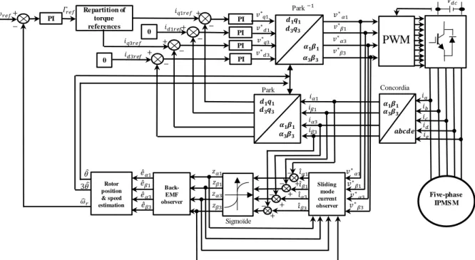
The overall block diagram of sensorless control of the FIPMSM and the observer based on sliding mode method are shown in Figure 1.
Figure 1: Block diagram of the proposed SMO for the sensorless control of FIPMSM with the consideration of third harmonic component Concordia Park Par Sliding mode current observer Back-EMF observer Rotor position & speed estimation Sigmoïde PI PI PI PI PI Five-phase IPMS M
PWM
Repartition of torque references 0 0Oléron – 11-14 juin 2019
7
(b) (a)
Table 2. parameters of the five phase IPMSM
Parameters Units Values
Rated voltage V 48 Rated power kW 8 Base speed rpm 1300 Speed-normalized amplitude of 1st harmonic EMF V/rad/s 0.1358 Speed-normalized amplitude of 3rd harmonic EMF V/rad/s 0.01356 Stator resistance Ω 0.0091 Stator inductance mH 0.09 Pole pairs 7
Table 3. parameters of SMO for the sensorless control
Parameters Values 1 k 250 2 k 25 1 l 500 2 l 1000 a 0.1
4. Simulation results
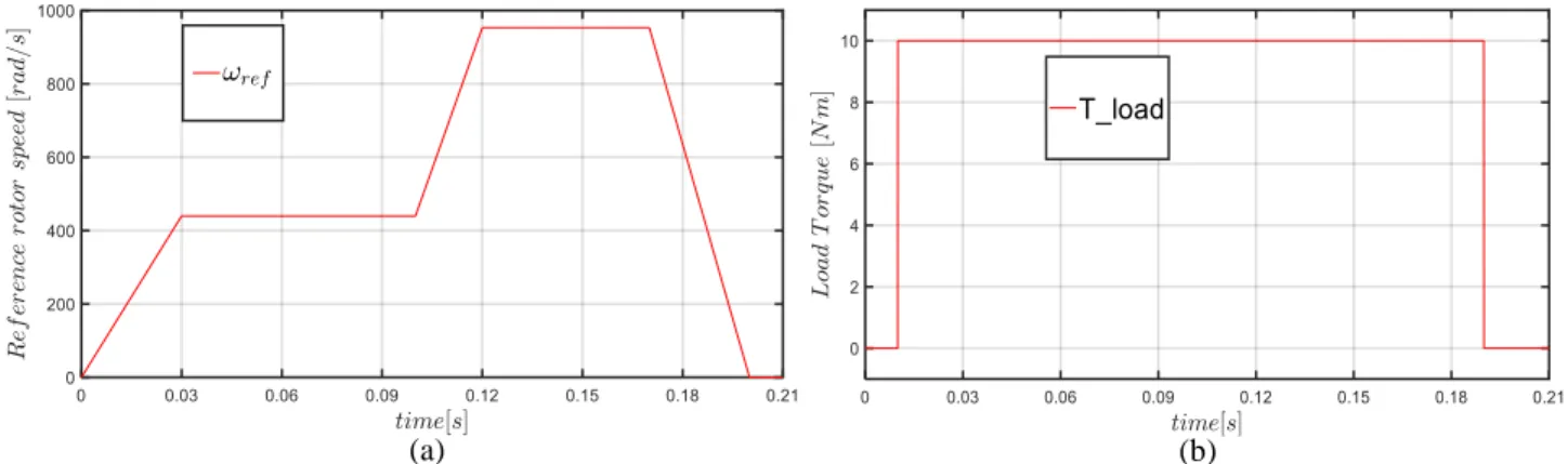
Based on the sliding mode observer describes above, we aim by the simulation is to verify the effectiveness of the proposed SMO for the sensorless control of the FIPMSM. The proposed system from Figure 1 has been implemented in the MATLAB/Simulink programming environment. The simulation uses as modulation strategy the space vector modulation (SVPWM), and the PWM switching frequency is 10kHz. The sampling time used for the sensorless control system shown in Figure 1 is set as 1 µs.
In this simulation, we consider a special cycle for the reference rotor speed (benchmark established by the French community of sensorless), in order to verify the stability and robustness of the proposed SMO against the speed and load torque variations. The FIPMSM parameters are provided in Table 2. The SMO parameters are provided in Table 3. The
0
=
d
i
control strategy is carried out. The Figure 2 (a) shows the reference rotor speed. the reference speed is from 0 to 1300 rpm. The application of load torque Figure2 (b) is as follow: 0 Nm at t= [0, 0.01 s[, 10 Nm at t= [0.01, 0.19 s[ and 0 Nm at t= [0.19, 0.21 s].Oléron – 11-14 juin 2019
8
(a) (b)
(a) (b)
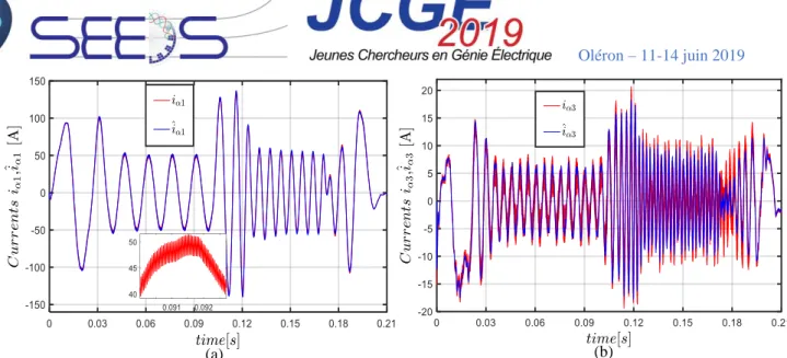
Figure 3. Simulation waveforms: (a) Actual and estimated fundamental current in α-axis, (b) Actual and estimated current of third harmonic in α-axis.
Figure 4. Simulation waveforms: (a) Actual and estimated fundamental of back-EMF in α-axis, (b) Actual and estimated third harmonic of back-EMF in α-axis.
It can be seen from Figure 3 and 4 that the current observer and back-EMF observer based on SMO estimate with high accuracy the current and the back-EMF of each fictitious machine in wide speed range. Therefore, the stability and robustness of the proposed SMO against the torque and speed variation are proved.
It can be seen also that, when the amplitude of the back-EMF of the main and secondary fictitious machine is low, the estimation process is not precise. Indeed, the estimation of rotor position in this range will be greatly impacted. In Figure 2 (a), the reference rotor speed cycle contains several transient state and steady state, that are used to examine the effectiveness of the proposed SMO. The estimated currents and back-EMF signals show that the proposed SMO is not impacted when the reference speed changes from steady state to transient state or vice versa.
It is possible to conclude that the load torque disturbance also has no obvious effect on the estimation process. The load torque is applied in transient state as in steady state. Therefore, it can be seen form Figure 4 that the estimated back-EMF signals of the first and third harmonic components are not impacted.
In Figure 3 (b), the current of the secondary fictitious machine is less than the current in the main fictitious machine. And it can be noted that the estimated current of the third harmonic is impacted by the high frequency component of the PWM, especially when the amplitude of the current is low.
Even though the third harmonic of the FIPMSM (parameters provided in Table 2) presents only 10% of the first harmonic, the sliding mode observer allows a precise estimation of the current and back-EMF of the secondary fictitious machine in wide speed range. So, it can be concluded that the third harmonic component can be used, in the case of FIPMSM, to estimate the rotor position.
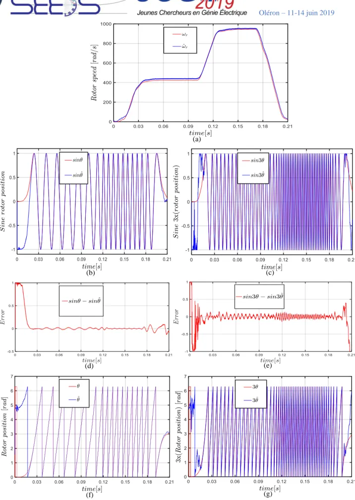
Oléron – 11-14 juin 2019 9 (a) (b) (c) (d) (e) (f) (g)
Fig. 5. Simulation waveforms: (a) Actual and estimated rotor speed, (b) sine actual and estimated rotor position of the main fictitious machine, (c) sine actual and estimated rotor position of the secondary fictitious machine, (d) error between the sine of actual and estimated rotor position of the main fictitious machine, (e) error between the sine of actual and estimated rotor position of the secondary fictitious machine (f) Actual rotor position and estimated rotor position by the first harmonic, (g)
Oléron – 11-14 juin 2019
10
Figure 5 shows the rotor position and speed of the machine for the reference rotor speed in Figure 2. It can be seen that the rotor position at zero and low speed (0 – 100 rpm) cannot be estimated. The estimation of the back-EMF at low speed is very disturbed. Therefore, the rotor position and velocity estimation is greatly affected. When the reference speed exceeds the low speed range, the SMO can effectively obtain the estimated rotor position and speed with accuracy in both steady state and transient state.
The error between the real and estimated , through the main fictitious machine (first harmonic), is less than 1.5 degree. And the error between the real and estimated 3 , through the secondary fictitious machine (third harmonic), is less than 5 degrees. This error between the real and estimated is evaluate in the medium speed range (100 – 1300 rpm). Thus, it can be concluded that, in the case of FIPMSM, the third harmonic can also be used to perform a sensorless control.
5. Conclusion
In this paper, an observer based on the sliding mode is designed for the sensorless control of non-sinusoidal back-EMF of FIPMSM. The simulation results show that the proposed SMO estimate rotor position and speed in wide speed range with accuracy. The proposed SMO with the consideration of the impact of third harmonic component (in FIPMSM) allows an accurate estimation of the rotor position, as the conventional SMO (with the consideration of only first harmonic). So, the proposed SMO can significantly improve the robustness and reliability of the control system by increasing the degrees of freedom of the control loop.
Acknowledgment
This work has been achieved within the framework of CE2I project. CE2I is co-financed by European Union with the financial support of European Regional Development Fund (ERDF), French State and the French Region of Hauts-de-France.
References
[1] (Apr. 23, 2019). Converter Energy Integrated Smart (CE2I). Available: http://ce2i.pole-medee.com/the-project/ [2] Y. Burkhardt, A. Spagnolo, P. Lucas, M. Zavesky, and P. Brockerhoff, "Design and analysis of a highly integrated 9-phase drivetrain for EV applications," in 2014 International Conference on Electrical Machines (ICEM), 2014, pp. 450-456.
[3] P. Vas, Sensorless Vector and Direct Torque Control Oxford University Press, 1998, pp. 1-729.
[4] L. Zhang, Y. Fan, C. Li, A. Nied, and M. Cheng, "Fault-Tolerant Sensorless Control of a Five-Phase FTFSCW-IPM Motor Based on a Wide-Speed Strong-Robustness Sliding Mode Observer," IEEE Transactions on Energy Conversion, vol. 33, no. 1, pp. 87-95, 2018.
[5] M. Ramezani and O. Ojo, "The Modeling and Position-Sensorless Estimation Technique for A Nine-Phase Interior Permanent-Magnet Machine Using High-Frequency Injections," IEEE Transactions on Industry Applications, vol. 52, no. 2, pp. 1555-1565, 2016.
[6] L. Parsa and H. A. Toliyat, "Sensorless Direct Torque Control of Five-Phase Interior Permanent-Magnet Motor Drives," IEEE Transactions on Industry Applications, vol. 43, no. 4, pp. 952-959, 2007.
[7] A. Hosseyni, R. Trabelsi, M. F. Mimouni, A. Iqbal, and R. Alammari, "Sensorless sliding mode observer for a five-phase permanent magnet synchronous motor drive," ISA Trans, vol. 58, pp. 462-73, Sep 2015.
[8] Z. Qiao, T. Shi, Y. Wang, Y. Yan, C. Xia, and X. He, "New Sliding-Mode Observer for Position Sensorless Control of Permanent-Magnet Synchronous Motor," IEEE Transactions on Industrial Electronics, vol. 60, no. 2, pp. 710-719, 2013.
[9] J. Yang, M. Dou, and D. Zhao, "Iterative sliding mode observer for sensorless control of five-phase permanent magnet synchronous motor," Bulletin of the Polish Academy of Sciences Technical Sciences, vol. 65, no. 6, pp. 845-857, 2017.
[10] E. Semail, X. Kestelyn, and A. Bouscayrol, "Right harmonic spectrum for the back-electromotive force of an n-phase synchronous motor," in Conference Record of the 2004 IEEE Industry Applications Conference, 2004. 39th IAS Annual Meeting., 2004, vol. 1, pp. 1-78.
![Table 1. Fictitious machines and associated harmonics of FIPMSM [10]](https://thumb-eu.123doks.com/thumbv2/123doknet/7325671.211140/3.892.88.768.149.360/table-fictitious-machines-associated-harmonics-fipmsm.webp)