HAL Id: hal-02886510
https://hal-imt-atlantique.archives-ouvertes.fr/hal-02886510
Submitted on 1 Jul 2020
HAL is a multi-disciplinary open access
archive for the deposit and dissemination of
sci-entific research documents, whether they are
pub-lished or not. The documents may come from
teaching and research institutions in France or
abroad, or from public or private research centers.
L’archive ouverte pluridisciplinaire HAL, est
destinée au dépôt et à la diffusion de documents
scientifiques de niveau recherche, publiés ou non,
émanant des établissements d’enseignement et de
recherche français ou étrangers, des laboratoires
publics ou privés.
Resource Allocation in Full-Duplex Uncoordinated
Communication Systems with NOMA
Antoine Kilzi, Joumana Farah, Charbel Abdel Nour, Catherine Douillard
To cite this version:
Antoine Kilzi, Joumana Farah, Charbel Abdel Nour, Catherine Douillard. Resource Allocation in
Full-Duplex Uncoordinated Communication Systems with NOMA. PIMRC 2020: IEEE 32nd Annual
International Symposium on Personal, Indoor and Mobile Radio Communications, IEEE, Sep 2021,
Oulu (Virtual conference), Finland. �hal-02886510�
Inband Full-Duplex D2D Communications
Underlaying Uplink Networks with Mutual SIC
NOMA
Antoine Kilzi
(1), Joumana Farah
(2), Charbel Abdel Nour
(1), Catherine Douillard
(1)(1)IMT Atlantique, Department of Electronics, Lab-STICC - UMR 6285 Technopˆole Brest Iroise, CS 83 818 - 29238 Brest Cedex, France (2)Department of Electricity and Electronics, Faculty of Engineering,
Lebanese University, Roumieh, Lebanon
Abstract—This paper studies the combination of full-duplex (FD) and half-duplex (HD) device-to-device (D2D) communi-cations while underlaying a cellular system. Non-orthogonal multiple access (NOMA) is used to manage the interference between devices and cellular users using mutual successive inter-ference cancellation (SIC) and to boost the performance of D2D underlay systems, which are mainly interference-limited. For this purpose, we derive the conditions allowing for the application of mutual SIC in FD-D2D and HD-D2D systems. We compare the performance of the proposed strategy against state-of-the-art, where SIC is not applied between D2D devices and cellular users. The results show that important gains can be achieved by using NOMA in this context and highlight the importance of self-interference (SI) cancellation factors for determining the best transmission mode.
Index Terms—Non-orthogonal multiple access, D2D, mutual SIC, full duplex, half duplex, residual self interference.
I. INTRODUCTION
The growth of the number of connected devices has hit unprecedented highs in the last few years, and this trend is set to last for the years to come [1]. Indeed, their number is expected to be more than three times the world population by 2023. The corresponding network densification, coupled with the expected increase in data traffic and the limited available spectrum, will require novel efficient solutions to supply the ever increasing demand. Full-duplex (FD) communication combined with device-to-device (D2D) communication repre-sent an attractive solution to leverage the challenges of future generation networks.
D2D enables direct communication between nearby devices with little to no information transiting through the network base stations (BS) [2]. The D2D communication rate, in this regard, is alleviated from the network which can use the freed capacity to serve other users, hence increasing the number of accommodated devices. FD communication enables a node to send and receive simultaneously using the same frequency resource. In theory, the achieved gain is a two-fold increase in spectral efficiency (SE) compared to half-duplex (HD) send-then-receive systems. However, a self interference (SI) is incurred due to the transmitted signal looping back into the receiver, thus limiting its appeal compared to HD to the point where this latter may even outperform FD in some cases.
Nonetheless, the improvement in antenna architecture and in SI cancellation circuitry dramatically reduces the residual self interference (RSI) [3], [4], pushing FD to be adopted in 5G.
The increasing demand for connected devices pushed re-search into the direction of non-orthogonal multiple access (NOMA) techniques. In NOMA, multiple devices can share the same time and frequency resource but are differentiated in a non-orthogonal dimension, e.g. code-domain and power-domain NOMA (PD-NOMA) [5]. In the latter, superposition coding of the user signals is used at the transmitter, and successive interference cancellation (SIC) is performed at the receiver side. The message with the highest power is decoded first and then subtracted from the total received signal, then the second highest power message is extracted and so on until the user decodes its own message [6–9].
In [10], a NOMA FD-D2D system is proposed, where FD is used at the level of the strong NOMA user in D2D relay mode to help and assist the weak NOMA user. This FD-D2D aided cooperative NOMA scheme can perform better than regular NOMA, depending on the RSI and channel constraints. This led to the elaboration of an adaptive multiple access scheme efficiently switching back to conventional NOMA when it is favorable. In [11], D2D is studied in the context of vehicle-to-vehicle (V2V) communication where strict latency conditions must be satisfied. The formulated problem accounts for the latency constraints and the proposed heuristic solution for the resource block allocation relies only on slow fading channel information. The same approach is followed in [12] to transform the latency and reliability requirements of vehicle-to-everything (V2X) communications into optimization con-straints. Moreover, non-orthogonal access for vehicle-type users is allowed and the optimization problem is formulated to maximize the cellular user (CU) rates while satisfying the latency and reliability constraints of V2X users.
The study in [13] considers resource block assignment and power allocation (PA) for the combination of NOMA with D2D communications in underlay mode. HD is used in the D2D pairs, and CUs are grouped in downlink NOMA clusters. However, NOMA SIC is not used to decode the interfering signals of the colocated D2D pairs. The same is true for [14], where additional power constraints are introduced to D2D
pairs for the sake of the CUs SIC decoding order conditions. The work in [15] introduces the concept of D2D group, where a D2D transmitter communicates with multiple D2D receivers via NOMA. Sub-channel allocation is conducted using many-to-one matching for CU-D2D grouping, and optimal PA is approximated iteratively via successive convex approximation. In [16], joint D2D-CU grouping and PA is conducted by suc-cessively applying the Kuhn-Munkres technique for channel allocation, while optimal PA is obtained using the Karush-Kuhn-Tucker conditions. The objective of these works is to maximize energy efficiency and/or system throughput under CU target rate constraints. In all the preceding studies, NOMA is applied either between the CU users [13], [14], or between users of the same D2D group [15], [16]. In our previous works [17–19], we introduced the concept of mutual SIC, where we showed that the signals of two or more users multiplexed in NOMA, and powered by distributed antennas, can be decoded and removed at the level of every user in the NOMA cluster. To the best of our knowledge, NOMA has not been applied between CU and D2D users; and even less for the case of FD-D2D underlay. We hear by NOMA between FD-D2D and CU, the intervention of the BS in signaling and power control to enable the interference cancellation of D2D signals at the level of the BS, and the cancellation of the CU message at the level of the D2D pair. This is done by applying mutual SIC between the D2D pair and the BS. The necessary SIC constraints in terms of power multiplexing conditions (PMC) and rate conditions are derived. Also, the PA problems are formulated and solved for the cases of FD and HD transmissions, as well as for SIC-enabled and disabled scenarios. The paper is organized as follows: section II presents the considered system model and formulates the PA problem for FD and HD with and without mutual SIC. In section III, the conditions of mutual SIC for FD-D2D are derived, and in section IV constraint reduction of the mutual SIC PA problem is performed. In section V, mutual SIC PA is solved for the case of HD transmission. Simulation results are presented in section VI, and conclusions are drawn in section VII.
II. SYSTEMMODEL
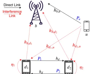
Consider a cellular network consisting of one D2D pair transmitting over an uplink (UL) channel previously allocated to a CU 𝑢. The D2D pair can transmit either in HD or in FD mode, while the CU is always in HD. A schematic of the network is presented in Fig. 1, where 𝑑1 and 𝑑2 are the D2D
users transmitting in FD mode. The interference channel gains between the CU, on the one hand, and 𝑑1and 𝑑2 on the other
hand are denoted by ℎ𝑑1,𝑢 and ℎ𝑑2,𝑢 respectively. The direct
link between the CU 𝑢 and the BS 𝑏 has a gain denoted by ℎ𝑏 ,𝑢. The signal 𝑠𝑢, transmitted by 𝑢 with power 𝑃𝑢, reaches
the BS with a power level 𝑃𝑢ℎ𝑏 ,𝑢, and causes an interference
level of 𝑃𝑢ℎ𝑑1,𝑢 and 𝑃𝑢ℎ𝑑2,𝑢 at 𝑑1 and 𝑑2 respectively. Each
device 𝑑𝑖of the D2D pair can transmit a signal 𝑠𝑖 of power 𝑃𝑖
to the other D2D user and suffers from both the interference of user 𝑢 and its RSI power 𝜂𝑖𝑃𝑖, with 𝜂𝑖 the SI cancellation
capability. The D2D channel gain is denoted by ℎ𝑑 and the
interference channel gains from 𝑑1 and 𝑑2 to the BS are
denoted by ℎ𝑏 , 𝑑1 and ℎ𝑏 , 𝑑2. In this work, we assume that the
BS has perfect knowledge of the long-term evolution of the different channel gains, through signaling exchange between the different entities. The BS performs resource allocation based on these estimated channel gains and instructs the CU and D2D pair of the required transmit power according to the selected transmission scenario.
1 ℎ
ℎ
,ℎ
, 1ℎ
, 2ℎ
1,ℎ
2, 2 ℎ 1 2 Direct Link Interference Link 1 2Figure 1: FD inband underlay communication sharing the UL resource of a CU.
A. PA problem formulation for FD and HD scenarios without mutual interference cancellation
The idea behind inband underlay D2D lies in reusing licensed spectrum to allow for the communication of more users without affecting the quality of service (QoS) of the CU. Therefore, the objective of all the presented transmission scenarios is to maximize the D2D rate while maintaining the QoS requirement of user 𝑢. The generic problem can be written as follows: {𝑃∗1, 𝑃∗ 2, 𝑃 ∗ 𝑢} = arg max 𝑅𝐷2𝐷, (1) s.t. 𝑅𝑢 ≥ 𝑅𝑢 , 𝑚𝑖 𝑛, (1a) 𝑃1 ≤ 𝑃1,𝑚𝑎𝑥, (1b) 𝑃𝑢 ≤ 𝑃𝑢 , 𝑚𝑎 𝑥, (1c) 𝑃2≤ 𝑃2,𝑚𝑎𝑥, (1d) where 𝑃𝑢 , 𝑚𝑎 𝑥, 𝑃1,𝑚𝑎𝑥, and 𝑃2,𝑚𝑎𝑥 are the maximum
trans-mit powers of users 𝑢, 𝑑1 and 𝑑2 respectively, 𝑅𝑢 , 𝑚𝑖 𝑛 is the
minimum target rate of user 𝑢 with 𝑅𝑢 its achieved rate,
and 𝑅𝐷2𝐷 is the D2D rate, sum of the achieved rates by 𝑑1
(𝑅𝑑1) and 𝑑2 (𝑅𝑑2). The problem formulation in (1) is used
throughout the paper as a generic form for all transmission scenarios with the proper modifications in the rate expressions. 1) FD-NoSIC: In FD, 𝑑1 and 𝑑2 transmit simultaneously,
signal-to-interference-plus-noise ratios (SINRs) at the level of the BS and the D2D users are given by:
𝑆 𝐼 𝑁 𝑅𝑏= 𝑃𝑢ℎ𝑏 ,𝑢 𝑃1ℎ𝑏 , 𝑑1+ 𝑃2ℎ𝑏 , 𝑑2+ 𝜎2 , 𝑆 𝐼 𝑁 𝑅𝑑1= 𝑃2ℎ𝑑 𝑃𝑢ℎ𝑑1,𝑢+ 𝜂1𝑃1+ 𝜎2 , (2) 𝑆 𝐼 𝑁 𝑅𝑑2= 𝑃1ℎ𝑑 𝑃𝑢ℎ𝑑2,𝑢+ 𝜂2𝑃2+ 𝜎2 ,
with 𝜎2the additive Gaussian noise power. The achieved rates
are expressed according to the Shannon capacity theorem: 𝑅𝑢 = 𝐵log2(1 + 𝑆𝐼 𝑁 𝑅𝑏), (3)
𝑅𝑑1 = 𝐵log2(1 + 𝑆𝐼 𝑁 𝑅𝑑1), 𝑅𝑑2 = 𝐵log2(1 + 𝑆𝐼 𝑁 𝑅𝑑2),
(4) with 𝐵 the bandwidth of the UL resource initially allocated to 𝑢. Due to the interference terms in (2), (1) is a non-convex problem. To solve it, a geometrical representation can be used, leading to the analytical global solution in [20]. This method is adopted in our work to derive the results of the FD-NoSIC scenario in the performance assessment section.
2) HD-NoSIC: The time slot is now divided into two equal half time slots where 𝑑1and 𝑑2alternately transmit and receive
information. To maximize the total D2D rate, the optimization is conducted in the two half time slots. In the first half, 𝑑1
transmits information (𝑃2 =0). In (1), the objective function
and CU rate are now:
𝑅𝐷2𝐷,1 = 𝑅𝑑2 = 𝐵log2(1 + 𝑃1ℎ𝑑 𝑃𝑢 ,1ℎ𝑑2,𝑢+ 𝜎2 ), 𝑅𝑢 ,1= 𝐵log2(1 + 𝑃𝑢 ,1ℎ𝑏 ,𝑢 𝑃1ℎ𝑏 , 𝑑1+ 𝜎2 ).
In the first half time slot, problem (1) is constrained only by eqs. (1a) to (1c). Note that 𝑃𝑢 ,1 is the transmit power of 𝑢
during the first half time slot. 𝑅𝐷2𝐷,1 is strictly increasing
with 𝑃1 and decreasing with 𝑃𝑢 ,1; therefore, to maximize
𝑅𝐷2𝐷,1 = 𝑅𝑑2, 𝑃1 should be increased and 𝑃𝑢 ,1 decreased
as long as 𝑅𝑢 ,1 satisfies the minimum rate condition.
Con-sequently, 𝑃1 should be increased as much as possible and
then 𝑃𝑢 ,1 is obtained as a function of 𝑃1 (𝑃𝑢 ,1 = 𝑓 (𝑃1)) by
enforcing an equality between 𝑅𝑢 ,1 and 𝑅𝑢 , 𝑚𝑖 𝑛. If for 𝑃1 =
𝑃1,𝑚𝑎𝑥, 𝑓 (𝑃1,𝑚𝑎𝑥) ≤ 𝑃𝑢 , 𝑚𝑎 𝑥, the couple (𝑃1,𝑚𝑎𝑥, 𝑓(𝑃1,𝑚𝑎𝑥))
is retained as the (𝑃1, 𝑃𝑢 ,1) solution; otherwise, the couple
( 𝑓−1(𝑃
𝑢 , 𝑚𝑎 𝑥), 𝑃𝑢 , 𝑚𝑎 𝑥) delivers the best solution. The same
reasoning is applied for the second half time slot (where 𝑃1 =0) to maximize 𝑅𝐷2𝐷,2 = 𝑅𝑑1. The total D2D and user
𝑢 rates are given by: 𝑅𝑢 = 1 2𝑅𝑢 ,1+ 1 2𝑅𝑢 ,2, (5) 𝑅𝐷2𝐷= 1 2𝑅𝑑1+ 1 2𝑅𝑑2. (6)
B. PA problem formulation for HD and FD with mutual SIC (HD-SIC and FD-SIC)
Using a SIC receiver at the level of the BS and the D2D users, interfering signals can be decoded then subtracted from
the received signal, canceling thereby the interference in both FD and HD scenarios. In the case of FD, the BS can decode and subtract successively 𝑠1 then 𝑠2, or reversely, before
proceeding to the decoding of 𝑠𝑢; hence, two decoding orders
are possible. Users 𝑑1and 𝑑2 can also remove the interference
of 𝑢, leading to the following SINR expressions: 𝑆 𝐼 𝑁 𝑅𝑑1 = 𝑃2ℎ𝑑 𝜂1𝑃1+ 𝜎2 , 𝑆 𝐼 𝑁 𝑅𝑑2 = 𝑃1ℎ𝑑 𝜂2𝑃2+ 𝜎2 , 𝑆 𝐼 𝑁 𝑅𝑏= 𝑃𝑢ℎ𝑏 ,𝑢 𝜎2 . The SINRs are replaced in eqs. (3) and (4) to obtain 𝑅𝑢 and
𝑅𝐷2𝐷= 𝑅𝑑1+ 𝑅𝑑2. For the case of HD, the SINRs in the first
half time slot are: 𝑆 𝐼 𝑁 𝑅𝑑2 = 𝑃1ℎ𝑑/𝜎
2, 𝑆 𝐼 𝑁 𝑅
𝑏= 𝑃𝑢ℎ𝑏 ,𝑢/𝜎 2.
In the second half time slot, 𝑆𝐼 𝑁 𝑅𝑏 is the same and 𝑆𝐼 𝑁 𝑅𝑑1 =
𝑃2ℎ𝑑/𝜎2. Problem (1) is now reformulated in each time slot
by expressing the rates using the present SINRs. However, additional constraints relative to the SIC feasibility must be added to the problem. They are derived next.
III. DERIVATION OF THESICCONDITIONS FORFD
MUTUALSIC
In this scenario, we are looking for the conditions that allow 𝑑1 to decode 𝑠𝑢, 𝑑2 to decode 𝑠𝑢, and 𝑏 to decode 𝑠1 and 𝑠2.
As already mentioned, two decoding orders are possible at the level of 𝑏.
A. First decoding order: 𝑏 decodes 𝑠2 then 𝑠1
We first start by studying the mutual SIC constraints be-tween 𝑏 and 𝑑1 (as a receiver). Let 𝑆𝐼 𝑁 𝑅
𝑠𝑗
𝑖 be the SINR of
the signal 𝑠𝑗 at the level of user 𝑖 (𝑖 is either 𝑑1, 𝑑2 or 𝑏, and
𝑗 is either1, 2 or 𝑢). For 𝑏 to successfully decode the signal 𝑠2 transmitted by 𝑑2to 𝑑1, the rate of 𝑠2 at the level of 𝑏 must be greater than the rate of 𝑠2 at the level of 𝑑1. Thus, we must
have: 𝑆 𝐼 𝑁 𝑅𝑠2 𝑏 > 𝑆 𝐼 𝑁 𝑅𝑠2 𝑑1 , 𝑃2ℎ𝑏 , 𝑑2 𝜎2+ 𝑃1ℎ𝑏 , 𝑑1+ 𝑃𝑢ℎ𝑏 ,𝑢 > 𝑃2ℎ𝑑 𝜎2+ 𝑃1𝜂1+ 𝑃𝑢ℎ𝑑1,𝑢 . By neglecting the noise power compared to the interfering terms, the SIC condition is given by:
𝑃1(ℎ𝑏 , 𝑑2𝜂1− ℎ𝑑ℎ𝑏 , 𝑑1) + 𝑃𝑢(ℎ𝑑1,𝑢ℎ𝑏 , 𝑑2− ℎ𝑑ℎ𝑏 ,𝑢) > 0. (7)
In addition to condition (7), the PMCs must be verified. The PMC ensures that the signal to be decoded first at the level of a receiver must have a higher power level than the remaining signals combined [19]. Since 𝑏 decodes 𝑠2 first, then we have
the following PMC for the decoding of 𝑠2.
𝑃2ℎ𝑏 , 𝑑2 > 𝑃1ℎ𝑏 , 𝑑1+ 𝑃𝑢ℎ𝑏 ,𝑢. (8)
For 𝑑1 to remove the interference of 𝑠𝑢 prior to retrieving 𝑠2,
we must have 𝑆𝐼 𝑁 𝑅𝑠𝑢
𝑑1
> 𝑆 𝐼 𝑁 𝑅𝑠𝑢
𝑏 , which leads to:
𝑃1(ℎ𝑑1,𝑢ℎ𝑏 , 𝑑1− ℎ𝑏 ,𝑢𝜂1) +𝑃2(ℎ𝑑1,𝑢ℎ𝑏 , 𝑑2− ℎ𝑏 ,𝑢ℎ𝑑) > 0, (9)
and the corresponding PMC is:
Regarding the mutual SIC between the receivers 𝑏 and 𝑑2, the
decoding of 𝑠1 at the level of 𝑏 requires 𝑆𝐼 𝑁 𝑅 𝑠1 𝑏 to be greater than 𝑆𝐼 𝑁 𝑅𝑠1 𝑑2: 𝑃1ℎ𝑏 , 𝑑1 𝜎2+ 𝑃𝑢ℎ𝑏 ,𝑢 > 𝑃1ℎ𝑑2, 𝑑1 𝜎2+ 𝑃2𝜂2+ 𝑃𝑢ℎ𝑑2,𝑢 , 𝑃2ℎ𝑏 , 𝑑1𝜂2> 𝑃𝑢(ℎ𝑏 ,𝑢ℎ𝑑− ℎ𝑑2,𝑢ℎ𝑏 , 𝑑1). (11) Note that 𝑆𝐼 𝑁 𝑅𝑠1
𝑏 does not include 𝑃2since 𝑠2is decoded and
canceled prior to 𝑠1. The corresponding PMC is given by:
𝑃1ℎ𝑏 , 𝑑1 > 𝑃𝑢ℎ𝑏 ,𝑢. (12)
At the level of 𝑑2, 𝑆𝐼 𝑁 𝑅 𝑠𝑢
𝑑2 must be greater than 𝑆𝐼 𝑁 𝑅 𝑠𝑢
𝑏 to
decode and subtract 𝑠𝑢 before retrieving 𝑠1. This yields the
following condition:
𝑃1(ℎ𝑏 , 𝑑1ℎ𝑑2,𝑢− ℎ𝑑ℎ𝑏 ,𝑢) > 𝑃2𝜂2ℎ𝑏 ,𝑢 (13)
Finally, the PMC at the level of 𝑑2 is given by:
𝑃𝑢ℎ𝑑2,𝑢> 𝑃1ℎ𝑑+ 𝑃2𝜂2 (14)
B. Second decoding order: 𝑏 decodes 𝑠1 then 𝑠2
Following the same reasoning as in Section III-A, for the case where 𝑠1 is decoded before 𝑠2 at the level of 𝑏, the PMC
and rate constraints for a full SIC between 𝑑1 and 𝑏, and 𝑑2
and 𝑏, are obtained and listed below:
𝑃1𝜂1ℎ𝑏 , 𝑑2 > 𝑃𝑢(ℎ𝑏 ,𝑢ℎ𝑑− ℎ𝑏 , 𝑑2ℎ𝑏 , 𝑑1) (15) 𝑃2(ℎ𝑑1,𝑢ℎ𝑏 , 𝑑2− ℎ𝑢 , 𝑏ℎ𝑑) > ℎ𝑢 , 𝑏𝜂1𝑃1 (16) 𝑃2(ℎ𝑏 , 𝑑1𝜂2− ℎ𝑏 , 𝑑2ℎ𝑑) +𝑃𝑢(ℎ𝑏 , 𝑑2ℎ𝑏 , 𝑑1− ℎ𝑏 ,𝑢ℎ𝑑) > 0 (17) 𝑃1(ℎ𝑑2,𝑢ℎ𝑏 , 𝑑1− ℎ𝑑ℎ𝑢 , 𝑏) +𝑃2(ℎ𝑑2𝑏ℎ𝑑2,𝑢− ℎ𝑢 , 𝑏𝜂2) > 0 (18) 𝑃2ℎ𝑏 , 𝑑2 > 𝑃𝑢ℎ𝑏 ,𝑢 (19) 𝑃𝑢ℎ𝑑1,𝑢> 𝑃2ℎ𝑑+ 𝑃1𝜂1 (20) 𝑃1ℎ𝑏 , 𝑑1 > 𝑃𝑢ℎ𝑏 ,𝑢+ 𝑃2ℎ𝑏 , 𝑑2 (21) 𝑃𝑢ℎ𝑑2,𝑢> 𝑃1ℎ𝑑+ 𝑃2𝜂2 (22)
Problem (1) now includes, in addition to constraints eqs. (1a) to (1d), eight new constraints that express the full SIC feasibility (either equations (7) to (14) or (15) to (22), depending on the decoding order). In the next section, we analyze the interplay between SIC rate conditions and PMCs in order to remove redundant constraints from problem (1).
IV. PROBLEMSIMPLIFICATION OFFD-SICBY
CONSTRAINTREDUCTION
Consider the first decoding order at the level of 𝑏 where 𝑠2 is decoded before 𝑠1. The PMCs for the decoding of 𝑠1 at the level of 𝑏 and of 𝑠𝑢 at the level of 𝑑2 are given by (12)
and (14). By multiplying (12) by ℎ𝑑2,𝑢 and adding it to (14)
multiplied by ℎ𝑏 ,𝑢, one can eliminate 𝑃𝑢 to obtain:
𝑃1(ℎ𝑏 , 𝑑1ℎ𝑑2,𝑢− ℎ𝑑ℎ𝑏 ,𝑢) > 𝑃2𝜂2ℎ𝑏 ,𝑢,
which is the SIC condition (13) to remove 𝑠𝑢at the level of 𝑑2.
Also, eliminating 𝑃1 from the two PMCs by means of adding
(12) multiplied by ℎ𝑑 to (14) multiplied by ℎ𝑏 , 𝑑1 yields (11).
Consequently, the PMCs for the decoding of 𝑠1 at the level
of 𝑏, and 𝑠𝑢 at the level of 𝑑2 imply their counterpart rate
conditions. Moreover, a necessary channel condition for the application of SIC between 𝑑2 and 𝑏 is identified from (13):
ℎ𝑏 , 𝑑1ℎ𝑑2,𝑢> ℎ𝑑ℎ𝑏 ,𝑢 (23)
Note that if (23) is false, (13) becomes impossible to satisfy no matter 𝑃1 and 𝑃2; however, when (23) is true, (13) can be
held true under an adequate power play between 𝑃1 and 𝑃2.
We now move to the PMC and SIC conditions for the decoding of 𝑠2 and 𝑠𝑢 at the level of 𝑏 and 𝑑1 respectively,
i.e. (8), (10), (7) and (9). By adding (8) multiplied by ℎ𝑑 to
(10) multiplied by ℎ𝑏 , 𝑑2, 𝑃2 is eliminated to yield:
𝑃𝑢(ℎ𝑑1,𝑢ℎ𝑏 , 𝑑2− ℎ𝑏 ,𝑢ℎ𝑑) > 𝑃1(ℎ𝑏 , 𝑑1ℎ𝑑+ 𝜂1ℎ𝑏 , 𝑑2), (24)
which can be further transformed into:
𝑃1(𝜂1ℎ𝑏 , 𝑑2− ℎ𝑏 , 𝑑1ℎ𝑑) + 𝑃𝑢(ℎ𝑑1,𝑢ℎ𝑏 , 𝑑2− ℎ𝑏 ,𝑢ℎ𝑑) > 2𝑃1𝜂1ℎ𝑏 , 𝑑2
⇒ 𝑃1(𝜂1ℎ𝑏 , 𝑑2− ℎ𝑏 , 𝑑1ℎ𝑑) + 𝑃𝑢(ℎ𝑑1,𝑢ℎ𝑏 , 𝑑2− ℎ𝑏 ,𝑢ℎ𝑑) > 0.
Thus, the PMCs (8) and (10) imply (7). In fact, not only do they imply the rate condition, but it is clear that the PMCs represent more restrictive constraints than rate conditions. Fi-nally, eliminating 𝑃𝑢 from the PMCs through the combination
of (8) multiplied by ℎ𝑑1,𝑢 with (10) multiplied by ℎ𝑏 ,𝑢 yields:
𝑃2(ℎ𝑏 , 𝑑2ℎ𝑑1,𝑢− ℎ𝑑ℎ𝑏 ,𝑢) > 𝑃1(ℎ𝑏 , 𝑑1ℎ𝑑1,𝑢+ 𝜂1ℎ𝑏 ,𝑢), (25)
which can be rearranged into:
𝑃2(ℎ𝑑1,𝑢ℎ𝑏 , 𝑑2− ℎ𝑏 ,𝑢ℎ𝑑) +𝑃1(ℎ𝑑1,𝑢ℎ𝑏 , 𝑑1− ℎ𝑏 ,𝑢𝜂1)>2𝑃1ℎ𝑏 , 𝑑1ℎ𝑑1,𝑢
⇒ (9).
Once again, the PMCs for the decoding of 𝑠2 and 𝑠𝑢 at 𝑏 and
𝑑1 imply their rate condition counterparts. Note that a new necessary channel condition appears from eqs. (24) and (25):
ℎ𝑑1,𝑢ℎ𝑏 , 𝑑2 > ℎ𝑏 ,𝑢ℎ𝑑 (26)
Also, the combinations of (12) with (10), and (14) with (8), while eliminating 𝑃𝑢, give the following conditions:
𝑃1(ℎ𝑏 , 𝑑1ℎ𝑑1,𝑢− 𝜂1ℎ𝑏 ,𝑢) > 𝑃2ℎ𝑑ℎ𝑏 ,𝑢
𝑃2(ℎ𝑏 , 𝑑2ℎ𝑑2,𝑢− 𝜂2ℎ𝑏 ,𝑢) > 𝑃1(ℎ𝑏 , 𝑑1ℎ𝑑2,𝑢+ ℎ𝑑ℎ𝑏 ,𝑢)
These inequalities yield two other necessary, but not sufficient, channel conditions for the application of full SIC to the system:
ℎ𝑏 , 𝑑1ℎ𝑑1,𝑢> 𝜂1ℎ𝑏 ,𝑢 (27)
ℎ𝑏 , 𝑑2ℎ𝑑2,𝑢> 𝜂2ℎ𝑏 ,𝑢 (28)
Repeating the same procedure for the second decoding order delivers the same results: 1) the PMCs encompass the rate conditions, 2) the same necessary four channel conditions are obtained. Therefore, in FD-SIC, the system checks the validity of eqs. (23) and (26) to (28) prior to solving the PA problem for each decoding order. The problem in (1) is only equipped with the PMC set corresponding to the decoding order (i.e. eqs. (8), (10), (12) and (14), or eqs. (19) to (22)), in addition to constraints eqs. (1a) to (1d). Because of the important number
of constraints, the problem is directly fed to a numerical solver for resolution. If the channel conditions do not comply or no solution is obtained for (1), the FD-SIC algorithm reverts to the FD-NoSIC procedure described in Section II-A1. In the next section, the problem solution for the case of HD-SIC is developed.
V. HD-SICSCENARIO
Consider the first half time slot, where 𝑢 and 𝑑1 are
transmitting and 𝑏 and 𝑑2 are receiving. The rate conditions
for the decoding of 𝑠1 at the level of 𝑏, and 𝑠𝑢 at the level 𝑑2,
are derived from 𝑆𝐼 𝑁 𝑅𝑠1
𝑏 > 𝑆 𝐼 𝑁 𝑅 𝑠1 𝑑2 and 𝑆𝐼 𝑁 𝑅 𝑠𝑢 𝑑2 > 𝑆 𝐼 𝑁 𝑅 𝑠𝑢 𝑏
respectively. This situation is equivalent to the case of two different radio resource heads (RRHs) transmitting the two signals to two separate receivers, and was studied in [17]. It was shown that the SINR conditions simply lead to the necessary condition (23) obtained in section IV of the present paper: ℎ𝑏 , 𝑑1ℎ𝑑2,𝑢 > ℎ𝑑ℎ𝑏 ,𝑢. The PMCs for 𝑠𝑢 and 𝑠1 at the
level of 𝑑2 and 𝑏 are given by:
𝑃𝑢 ,1ℎ𝑑2,𝑢> 𝑃1ℎ𝑑 𝑃1ℎ𝑏 , 𝑑1 > 𝑃𝑢 ,1ℎ𝑏 ,𝑢 ) ⇒ 𝐴 = ℎ𝑑 ℎ𝑑2,𝑢 < 𝑃𝑢 ,1 𝑃1 < ℎ𝑏 , 𝑑1 ℎ𝑏 ,𝑢 = 𝐵 (29) We note that (23) is contained in (29), since (23) is equivalent to 𝐴 < 𝐵. Therefore, just like for FD-SIC, the PMCs encompass the rate conditions while being more restrictive. Problem (1) now only includes the additional constraint (29) for the first time slot. The HD-SIC rate expressions are as follows: 𝑅𝐷2𝐷,1= 𝑅𝑑2 = 𝐵log2(1+ 𝑃1ℎ𝑑 𝜎2 ), 𝑅𝑢 ,1= 𝐵log2(1+ 𝑃𝑢 ,1ℎ𝑏 ,𝑢 𝜎2 ) Maximizing 𝑅𝑑2 lies in the increase of 𝑃1, and reaching
𝑅𝑢 , 𝑚𝑖 𝑛 is achieved by setting 𝑃𝑢 ,1 to 𝑃𝑢 , 𝑚𝑖 𝑛 = (2
𝑅𝑢 , 𝑚𝑖 𝑛 𝐵 −
1)𝜎2/ℎ𝑏 ,𝑢. However, due to the PMCs, the increase in 𝑃1
is very likely to increase 𝑃𝑢 ,1 according to the range of
allowed values in (29), leading to an excess of CU rate. Since maximization of network throughput (i.e. sum of D2D and CU rates) is not the objective of this study, we select from the range of admissible 𝑅𝑢 ,1 values, the one closest to 𝑅𝑢 , 𝑚𝑖 𝑛.
With that criterion in mind, the D2D rate maximization power allocation problem is solved by increasing 𝑃1 as much as
possible (possibly until 𝑃1,𝑚𝑎𝑥) and adjusting 𝑃𝑢 ,1
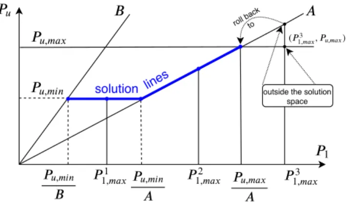
accord-ingly. The PA procedure, illustrated in Fig. 2, is as follows: if 𝑃1,𝑚𝑎𝑥 < 𝑃𝑢 , 𝑚𝑖 𝑛/𝐴, keep the couple (𝑃1 = 𝑃1,𝑚𝑎𝑥, 𝑃𝑢 ,1 =
𝑃𝑢 , 𝑚𝑖 𝑛). This case is represented by the example 𝑃 1 1,𝑚𝑎𝑥 on
the horizontal blue line in Fig. 2. If this is not the case, check if 𝐴𝑃1,𝑚𝑎𝑥 > 𝑃𝑢 , 𝑚𝑎 𝑥. If yes (cf. example 𝑃
3
1,𝑚𝑎𝑥 in Fig.
2), the solution is (𝑃𝑢 , 𝑚𝑎 𝑥/𝐴, 𝑃𝑢 , 𝑚𝑎 𝑥); if not (cf. example
𝑃2
1,𝑚𝑎𝑥), the solution is (𝑃1,𝑚𝑎𝑥, 𝐴𝑃1,𝑚𝑎𝑥). Restricting the
solution space to the blue lines in Fig. 2 guarantees that the CU always transmits at the minimum necessary power that respects the problem constraints. Note that if 𝑃1,𝑚𝑎𝑥 is too
low (< 𝑃𝑢 , 𝑚𝑖 𝑛/𝐵), the problem is not feasible even when (23)
is verified. For the second time slot, the same methodology
is followed, where eq. (26) reappears as a necessary channel condition. In this case, the PMCs are:
1 , , , , , 1,3 roll backto
outside the solution space ( 3 , ) 1, , solution lines 2 1, 1 1,
Figure 2: Schematic of the solution space to the HD-SIC PA problem, for different 𝑃1,𝑚𝑎𝑥 values.
𝐴 0 = ℎ𝑑 ℎ𝑑1,𝑢 < 𝑃𝑢 ,2 𝑃2 < ℎ𝑏 , 𝑑2 ℎ𝑏 ,𝑢 = 𝐵0 (30) As a conclusion, in the HD-SIC scenario, the system checks for the validity of the channel condition corresponding to the half time slot before going through the procedure described above. If the channel condition is not favorable or if no solution exists (i.e. 𝑃𝑢 , 𝑚𝑖 𝑛 > 𝑃𝑢 , 𝑚𝑎 𝑥 or 𝑃1,𝑚𝑎𝑥 < 𝑃𝑢 , 𝑚𝑖 𝑛/𝐵
for the first half, and 𝑃2,𝑚𝑎𝑥 < 𝑃𝑢 , 𝑚𝑖 𝑛/𝐵
0
for the second half), the system reverts to the HD-NoSIC solution of section II-A2. This leads to four combinations of SIC/NoSIC procedures, two for every half time slot, and they are all included in the HD-SIC algorithm.
VI. NUMERICALRESULTS
In our simulation setup, the BS is at the center of a hexagonal cell with an outermost radius of300 m. The D2D users are randomly located inside a disk of radius 50 m, centered100 m apart from the cell center, whereas the CU is randomly located anywhere within the cell. The propagation model includes large scale fading with a path loss exponent 𝛼=3.76, and an 8 dB zero mean lognormal shadowing. The maximum transmit power of the devices and CU is 24 dbm. The UL subband bandwidth is 156.25 kHz, with a noise power of −122 dbm. The SI cancellation factor 𝜂 = 𝜂1 = 𝜂2 varies
between −110 and −60 dB. The results are averaged over 10 000 different realizations of the devices and CU positions. The FD-SIC solutions are obtained using function fmincon from Matlab optimization toolbox.
Hereinafter, “Global” figures present the results averaged over all the simulated D2D-CU triplets, including both SIC success and failure cases (in case of failure, SIC algorithms revert to their NoSIC counterparts). On the other hand, the “SIC-only” figures present the results averaged over the cases of FD-SIC success.
The evolution of D2D rates with 𝜂 is shown in Fig. 3a and 3b, for a minimum target CU rate 𝑅𝑢 , 𝑚𝑖 𝑛 = 3 and 7
-110 -100 -90 -80 -70 -60 8 9 10 11 12 SE in bps/Hz FD-SIC FD-Nosic HD-Nosic HD-SIC (a) 𝑅𝑢 , 𝑚𝑖 𝑛=3 bps/Hz -110 -100 -90 -80 -70 -60 5 5.5 6 6.5 7 7.5 SE in bps/Hz FD-SIC FD-Nosic HD-Nosic HD-SIC (b) 𝑅𝑢 , 𝑚𝑖 𝑛=7 bps/Hz
Figure 3: Global D2D rates as a function of 𝜂.
bps/Hz respectively. As expected, the improvement of the SI cancellation capabilities increases the performance of FD algorithms, e.g. the D2D rate of FD-NoSIC in Fig. 3a falls from 10.9 to 9.8 bps/Hz when 𝜂 varies between −110 and −60 dB. Also the increase of QoS requirement impacts FD and HD algorithms by limiting the achieved rate (in FD-NoSIC, for 𝜂 = −60 dB, 𝑅𝐷2𝐷 =6.4 bps/Hz), and also by reducing
the range of variation of FD algorithms with 𝜂 (for FD-NoSIC, Δ 𝑅𝐷2𝐷 = 𝑅𝐷2𝐷(−110𝑑𝐵) − 𝑅𝐷2𝐷(−60𝑑𝐵) = 0.3 bps for
𝑅𝑢 , 𝑚𝑖 𝑛 = 7 bps/Hz, compared to 1.15 bps/Hz for 𝑅𝑢 , 𝑚𝑖 𝑛 =
3 bps/Hz). On the other hand, the HD curves are independent of 𝜂 since they do not suffer from SI. Note that in the case of NoSIC, FD always outperforms HD since, by shutting down the power of the adequate device, it can revert to the half time slot in HD delivering the best throughput and then extend it to the other half.
Regarding SIC algorithms, it is clear that FD-SIC and HD-SIC outperform their NoHD-SIC counterparts. In other terms, the SINR advantages of the SIC operation outweigh the burden incurred by the additional PMC constraints on the solution of problem (1). The gains of SIC with respect to FD-NoSIC become marginal when 𝜂 increases, which is due to two phenomenons. First, the number of simulation cases where FD-SIC succeeds (the result of these simulations is isolated in Fig. 4a and 4b) depends on the value of 𝜂; when 𝜂 increases, harder channel conditions are imposed in eqs. (27) and (28), thus less simulations yield a full SIC (420 cases out of 10 000 for 𝜂 = −110 dB, compared to 32 cases for 𝜂 = −60 dB). This is all the more significant as FD-NoSIC performs rather poorly in these conditions. Second, even when observing the SIC-only results in Figs. 4a and 4b, a high dependence upon the SI cancellation factor can be seen for FD-SIC with approximately 17 bps/Hz of dynamic range between 𝜂 = −60 and −110 dB. Since the interference of D2D users is RSI-limited in FD, with the SI cancellation getting better, the D2D rate increases until eventually the RSI’s order of magnitude becomes similar to background noise, closing out the gap between HD-SIC (which does not suffer from SI) and FD-SIC between 𝜂 = −110 dB and 𝜂 = −100 dB.
In the “Global” results, the intersection between FD-SIC and HD-SIC only occurs for high values of 𝑅𝑢 , 𝑚𝑖 𝑛 (as in Fig.
3b), taking place around 𝜂 = −80 dB. The reason behind this is that in Fig. 3a, the original smallest gap between
-110 -100 -90 -80 -70 -60 0 5 10 15 20 SE in bps/Hz FD-SIC FD-Nosic HD-Nosic HD-SIC data1 data2 0.02 0.04 0.06 (a) 𝑅𝑢 , 𝑚𝑖 𝑛=3 bps/Hz -110 -100 -90 -80 -70 -60 0 5 10 15 20 SE in bps/Hz FD-SIC FD-Nosic HD-Nosic HD-SIC data1 data2 0.001 0.002 0.003 (b) 𝑅𝑢 , 𝑚𝑖 𝑛=7 bps/Hz
Figure 4: SIC-only D2D rates as a function of 𝜂. FD-NoSIC and HD-NoSIC (∼ 1.9 bps/Hz) is such that the additional rate brought by HD-SIC (∼ 1.7 bps/Hz) with respect to HD-NoSIC is not sufficient to have an intersection. However, when 𝑅𝑢 , 𝑚𝑖 𝑛 = 7 bps/Hz, the FD/HD-NoSIC gap
decreases (∼ 1.3 bps/Hz) while the additional rate of HD-SIC is almost unchanged (∼ 1.6 bps/Hz), leading to the intersection mentioned previously. Fig. 3b clearly shows that no transmission mode is absolutely better than the other in the “Global” SIC scenario, as opposed to the supremacy of FD-NoSIC with regards to HD-NoSIC.
Moreover, it is observed in Figs. 3a and 3b that the improve-ment of FD-SIC with respect to FD-NoSIC is virtually the same, independently of the required QoS (around 0.8 bps/Hz for 𝜂 = −110 dB). This is even clearer in Fig. 4a and 4b, which are nearly identical despite the different required rates. To understand this behavior, attention is drawn to Fig. 2 where the optimal HD-SIC PA is depicted: whether 𝑃1,𝑚𝑎𝑥 is such
that the solution is in the order of 𝑃1,𝑚𝑎𝑥1 , 𝑃2
1,𝑚𝑎𝑥 or 𝑃 3 1,𝑚𝑎𝑥,
increasing 𝑅𝑢 , 𝑚𝑖 𝑛 simply raises the horizontal 𝑃𝑢 , 𝑚𝑖 𝑛 line.
Since the optimal PA is obtained from the intersection of the blue segments with the line 𝑃1 =min(𝑃1,𝑚𝑎𝑥, 𝑃𝑢 , 𝑚𝑎 𝑥/𝐴), the
abscissa of the optimal PA (𝑃1) is not affected in any ways by
𝑃𝑢 , 𝑚𝑖 𝑛, therefore the D2D rate is unchanged. This is the same
for the case of FD-SIC, leading to the same independence of the D2D rate from 𝑅𝑢 , 𝑚𝑖 𝑛.
2 4 6 5 10 15 20 SE in bps/Hz FD-SIC FD-Nosic HD-Nosic HD-SIC (a) Global 2 4 6 0 5 10 15 20 25 SE in bps/Hz FD-SIC FD-Nosic HD-Nosic HD-SIC 2 4 6 0 0.2 0.4 (b) SIC-only
Figure 5: D2D rates as a function of 𝑅𝑢 , 𝑚𝑖 𝑛 for 𝜂 = −110 dB.
Finally, Fig. 5 shows the evolution of the D2D rates as a function of the CU target rate, for 𝜂 = −110 dB. As expected, the global D2D rate of all the techniques decreases with 𝑅𝑢 , 𝑚𝑖 𝑛, as shown in Fig. 5a, with a clear advantage of
FD-SIC over all other methods. The gain of FD-SIC over FD-NoSIC and HD-SIC can reach respectively 0.75 and 3.7
bps/Hz. Based on the preceding explanations, the D2D rates of SIC-only results are practically independent from 𝑅𝑢 , 𝑚𝑖 𝑛,
with 19.9 bps/Hz gain for FD-SIC over FD-NoSIC and 18 bps/Hz for HD-SIC over HD-NoSIC.
VII. CONCLUSION
This paper studied the application of NOMA mutual SIC between D2D users and a cellular user in a full-duplex un-derlay system. The necessary conditions were derived for the SIC feasibility and incorporated in the corresponding power allocation problems. Simulation results confirm the usefulness of mutual SIC in always enhancing performance with respect to the classical NoSIC strategy in both HD and FD. FD-SIC and HD-SIC are shown to deliver the best results depending on the SI cancellation factor: FD-SIC is the best performing algorithm for important SI cancellation factors, while HD-SIC is the best algorithm for low SI cancellation performance. As a future work, adaptive mode selection and channel assignment between FD-SIC and HD-SIC for multiple D2D-CU triplets in a cell will be considered, with the aim of determining efficient geographical and positioning criteria.
ACKNOWLEDGMENT
This work has been funded with support from IMT Atlantique and the Lebanese University.
REFERENCES
[1] Cisco, “Cisco Visual Networking Index: Forecast and Trends, 2018-2023,” Mar. 2020.
[2] K. Doppler, M. Rinne, C. Wijting, C. B. Ribeiro, and K. Hugl, “Device-to-Device Communication as an Underlay to LTE-advanced networks,” IEEE Commun. Mag., vol. 47, no. 12, pp. 42–49, Dec 2009.
[3] K. E. Kolodziej, J. G. McMichael, and B. T. Perry, “Multitap RF Canceller for In-Band Full-Duplex Wireless Communications,” IEEE Trans. on Wireless Commun., vol. 15, no. 6, pp. 4321–4334, June 2016. [4] L. Laughlin, C. Zhang, M. A. Beach, K. A. Morris, and J. Haine, “A Widely Tunable Full Duplex Transceiver Combining Electrical Balance Isolation and Active Analog Cancellation,” in 2015 IEEE 81st Veh. Technol. Conf. (VTC Spring), May 2015, pp. 1–5.
[5] Y. Saito, A. Benjebbour, Y. Kishiyama, and T. Nakamura, “System-Level Performance Evaluation of Downlink Non-Orthogonal Multiple Access (NOMA),” in 2013 IEEE 24th Annual Int. Symp. on Personal, Indoor, and Mobile Radio Comm. (PIMRC), Sep 2013, pp. 611–615.
[6] J. Farah, E. Sfeir, C. Abdel Nour, and C. Douillard, “New Resource Allocation Techniques for Base Station Power Reduction in Orthogonal and Non-Orthogonal Multiplexing Systems,” in 2017 IEEE Int. Conf. on Commun. Workshops (ICC Workshops), May 2017, pp. 618–624. [7] M. J. Youssef, J. Farah, C. Abdel Nour, and C. Douillard, “Resource
Allocation for Mixed Traffic Types in Distributed Antenna Systems Using NOMA,” in 2018 IEEE 77th Veh. Technol. Conf. (VTC fall), Aug. 2018, pp. 1–5.
[8] Z. Ding, Z. Yang, P. Fan, and H. V. Poor, “On the Performance of Non-Orthogonal Multiple Access in 5G Systems with Randomly Deployed Users,” IEEE Signal Process. Lett., vol. 21, no. 12, pp. 1501–1505, Dec. 2014.
[9] Y. Saito, Y. Kishiyama, A. Benjebbour, T. Nakamura, A. Li, and K. Higuchi, “Non-Orthogonal Multiple Access (NOMA) for Cellular Future Radio Access,” in 2013 IEEE 77th Veh. Tech. Conf. (VTC Spring), June 2013, pp. 1–5.
[10] Z. Zhang, Z. Ma, M. Xiao, Z. Ding, and P. Fan, “Full-Duplex Device-to-Device-Aided Cooperative Nonorthogonal Multiple Access,” IEEE Trans. on Veh. Technol., vol. 66, no. 5, pp. 4467–4471, May 2017. [11] W. Sun, E. G. Str¨om, F. Br¨annstr¨om, Y. Sui, and K. C. Sou,
“D2D-based V2V Communications with Latency and Reliability Constraints,” in 2014 IEEE Globecom Workshops (GC Wkshps), Dec 2014, pp. 1414– 1419.
[12] W. Sun, D. Yuan, E. G. Str¨om, and F. Br¨annstr¨om, “Cluster-Based Radio Resource Management for D2D-Supported Safety-Critical V2X Communications,” IEEE Trans. on Wireless Commun., vol. 15, no. 4, pp. 2756–2769, April 2016.
[13] J. Chen, J. Jia, Y. Liu, X. Wang, and A. H. Aghvami, “Optimal Resource Block Assignment and Power Allocation for D2D-Enabled NOMA Communication,” IEEE Access, vol. 7, pp. 90 023–90 035, 2019. [14] Y. Pan, C. Pan, Z. Yang, and M. Chen, “Resource Allocation for D2D
Communications Underlaying a NOMA-Based Cellular Network,” IEEE Wireless Commun. Lett., vol. 7, no. 1, pp. 130–133, Feb 2018. [15] J. Zhao, Y. Liu, K. K. Chai, Y. Chen, and M. Elkashlan, “Joint
Subchan-nel and Power Allocation for NOMA Enhanced D2D Communications,” IEEE Trans. on Commun., vol. 65, no. 11, pp. 5081–5094, Nov 2017. [16] S. Alemaishat, O. A. Saraereh, I. Khan, and B. J. Choi, “An Efficient
Resource Allocation Algorithm for D2D Communications Based on NOMA,” IEEE Access, vol. 7, pp. 120 238–120 247, 2019.
[17] J. Farah, A. Kilzi, C. Abdel Nour, and C. Douillard, “Power Minimiza-tion in Distributed Antenna Systems Using Non-Orthogonal Multiple Access and Mutual Successive Interference Cancellation,” IEEE Trans. on Veh. Technol., vol. 67, no. 12, pp. 11 873–11 885, Dec. 2018. [18] A. Kilzi, J. Farah, C. A. Nour, and C. Douillard, “New Power
Min-imization Techniques in Hybrid Distributed Antenna Systems With Orthogonal and Non-Orthogonal Multiple Access,” IEEE Trans. on Green Commun. and Netw., vol. 3, no. 3, pp. 679–690, Sep. 2019. [19] A. Kilzi, J. Farah, C. Abdel Nour, and C. Douillard, “Mutual Successive
Interference Cancellation Strategies in NOMA for Enhancing the Spec-tral Efficiency of CoMP Systems,” IEEE Trans. on Commun., vol. 68, no. 2, pp. 1213–1226, Feb 2020.
[20] H. Chour, F. Bader, Y. Nasser, and O. Bazzi, “GALEN: A Geometric Framework for Global Optimal Power Allocation in a Full Duplex D2D Network,” in 2019 IEEE Wireless Commun. and Netw. Conf. (WCNC), April 2019, pp. 1–7.