HAL Id: pastel-00617985
https://pastel.archives-ouvertes.fr/pastel-00617985
Submitted on 31 Aug 2011HAL is a multi-disciplinary open access archive for the deposit and dissemination of sci-entific research documents, whether they are pub-lished or not. The documents may come from teaching and research institutions in France or abroad, or from public or private research centers.
L’archive ouverte pluridisciplinaire HAL, est destinée au dépôt et à la diffusion de documents scientifiques de niveau recherche, publiés ou non, émanant des établissements d’enseignement et de recherche français ou étrangers, des laboratoires publics ou privés.
in structured environments
Keerthi Narayana
To cite this version:
Keerthi Narayana. Solutions for the localization of mobile mapping systems in structured environ-ments. Automatic Control Engineering. École Nationale Supérieure des Mines de Paris, 2011. English. �NNT : 2011ENMP0020�. �pastel-00617985�
MINES ParisTech Centre de robotique
60 Boulevard Saint Michel 75006 Paris
présentée et soutenue publiquement par
M. Keerthi NARAYANA K.S
le 24 Mai 2011
Solutions de localisation des Systèmes Mobiles de Cartographie en
environnements structurés
***
Solutions for the localization of Mobile Mapping Systems in structured environments
Doctorat ParisTech
T H È S E
pour obtenir le grade de docteur délivré par
l’École Nationale Supérieure des Mines de Paris
Spécialité «
Informatique temps réel – Robotique – Automatique »
Directeur de thèse : M. François GOULETTE Co-encadrement de la thèse : M. Bruno STEUX
Jury
M. Saïd Mammar Professeur à l'Université d'Evry, HDR Rapporteur M. Juha Hyyppä Professeur Associé à l'Université Aalto (Finlande) Rapporteur M. Laurent Trassoudaine Professeur à l’Université Blaise-Pascal, HDR Président du jury M. François Goulette Enseignant Chercheur, MINES ParisTech, HDR Examinateur M. Bruno Steux Enseignant Chercheur, MINES ParisTech Examinateur
Ecole doctorale n° 432 : SMI-Sciences des métiers de l'ingénieur
T
H
E
S
E
SOLUTIONS FOR THE LOCALIZATION OF MOBILE MAPPING SYSTEMS IN
STRUCTURED ENVIRONMENTS
ABSTRACT:
Automated localization or in other words, the functionality to determine the position and orientation (pose) has several applications, such as autonomous navigation, search and rescue, and mobile mapping. This thesis focuses on proposing complimentary solutions to the current localization methods (performed using GPS receivers and Inertial Measurement Units (IMU)) of Mobile Mapping Systems (MMS), which are designed to generate 3D maps of the environments. First, the obvious errors in the already generated trajectory of the mapping platform are corrected using our smoothing‐based post‐mission processing. This approach is sufficient to correct the 3D maps to make them visually realistic. However, for precise localization this approach is still insufficient, especially when the input sensors have significant errors such as: GPS signal degradation or outage (due to the presence of obstacles to the satellite signal reception), and uncorrected IMU measurement biases (results as drifts in the estimated pose). These situations rise often in manmade environments, particularly in urban and indoor scenarios.The thesis therefore, proposes an alternative localization method using a set 2D laser scanners, which are normally used for perception/mapping in MMS. Our approach is comparable with the Simultaneous Localization and Mapping (SLAM) technique, used in indoor robotic navigation. However, the category of laser odometry is suitable, since the relative 3D transformation between two sets of landmarks is computed without using a map, but exploiting the time invariant properties of the extracted features from perception. Planar surfaces are one of the most recurring geometrical features available in manmade structured environments, and using their properties 3D transformation resolution is proposed.
In order to achieve this objective, first, a novel method to extract the planar landmarks using a synchronized pair of 2D laser scanners is proposed, to ensure a quick data extraction to retain the landmark’s time invariant properties intact, even while scanning from a vehicle in motion. Then we propose a Divide & Conquer (D&C) approach to simplify the transformation and landmark matching (Data Association) processes by splitting both the operations in two. The critical factor, in this approach is, the ability to obtain the minimal set of associations from a larger set, containing potential ambiguities and outliers, occurring due to the compensation in association, for unknown transformation. The new algorithm, Optimal Candidate Selection by Consensus (OCSC), and its weighted variant (WOCSC) handles not only this, but also computes the optimal transformation itself. The algorithm performs significantly better with noisy data, compared to the standard mean‐based approach. Finally, prior concluding, we propose our designed method called “Delayed Map Update”, to address the common problem of drift errors, affecting all odometry or SLAM approaches, while converting the computed noisy relative transformation to an absolute pose, by integration.
KEY WORDS
: Localization, Mobile Mapping Systems (MMS), SLAM, GPS receivers, InertialMeasurement Units (IMU), Laser scanners, Post-Mission processing, Laser odometry, Planar landmarks, Data association.
RESUMÉ: La localisation automatique, autrement dit la possibilité de déterminer la position et l'orientation (pose) d'un système mobile, trouve de nombreuses applications dans la navigation autonome, la recherche et le sauvetage ou la cartographie mobile. La présente thèse a pour objectif de compléter les méthodes employées jusqu'ici, pour assurer la localisation de systèmes de cartographie mobiles (MMS) (récepteurs GPS et centrales à inertie – IMU – le plus classiquement). Ces systèmes sont conçus pour générer des cartes en trois dimensions (3D) de leur environnement.
Dans un premier temps un post‐traitement, par lissage des données, permet de corriger certaines erreurs manifestes, dans les données d'une trajectoire enregistrée. Cette approche est acceptable pour redonner un aspect visuel réaliste à des cartes en 3D. Une telle approche n'est évidemment pas applicable quand une localisation précise est demandée, bien que certains capteurs fournissent des données erronées. Citons à titre d'exemples courants la dégradation ou la disparition momentanée du signal GPS (dues à la présence d'obstacles), les dérives des centrales à inertie. De telles situations sont fréquentes dans les environnements structurés par l'Homme : les sites urbains ou les intérieurs de bâtiments.
La présente thèse se propose d'utiliser, comme outil complémentaire de localisation, un ensemble de scanners à lasers 2D, ceux là mêmes qui sont employés comme capteurs dimensionnels dans les systèmes de cartographie mobile. Notre approche est voisine de la technique employée pour assurer la navigation des robots en espaces intérieurs : la localisation et la cartographie simultanées (SLAM). Il est justifié d'employer l'expression d'odométrie par laser, puisque le déplacement apparent de points de repères est calculé, en 3 dimensions, sans avoir besoin de carte, en utilisant des propriétés invariantes de l'environnement reconstruit. Les environnements artificiels sont souvent riches en portions de surfaces planes, il est donc proposé ici d'en exploiter leurs propriétés, pour déterminer un mouvement en 3D. Dans une première étape, nous proposons une nouvelle méthode qui permet de caractériser rapidement les repères plans, ainsi que leurs propriétés invariantes, même à partir d'un véhicule en mouvement. Nous utilisons pour ce faire une paire de scanners à lasers 2D, synchronisés entre eux.
Nous proposons ensuite une approche par “division pour régner” (divide and conquer, D&C) qui simplifie les tâches d'association des repères et de reconstruction du mouvement (data association, DA) :chacune de ces tâches est elle‐même divisée en deux. L'élément critique de cette approche consiste à extraire l'ensemble minimum d'associations, qui permettent de reconstruire le mouvement inconnu, à partir d'un ensemble beaucoup plus vaste d'associations apparemment plausibles, comportant des ambiguïtés, voire des cas aberrants. Un nouvel algorithme de sélection des candidats optimaux par consensus (OCSC), et sa variante pondérée (WOCSC), permettent cette extraction. Ces mêmes algorithmes permettent, de plus, de calculer la transformation la plus probable. Cet ensemble d'algorithmes présente une meilleure résistance, face à des données bruitées, que ceux qui font appel aux classiques approches statistiques. Finalement, avant de conclure, nous proposons notre méthode, appelée “mise à jour différée d'une carte”, pour résoudre le problème bien connu des dérives. Ces erreurs concernent toutes les techniques fondées sur l'odométrie ou les SLAM, elles prennent leur source dans le passage, par intégration, de la mesure bruitée de transformations relatives, en une position absolue.
MOTS CLÉS : Localisation, Systèmes de cartographie mobiles (MMS), SLAM, Récepteurs GPS, Centrales à inertie (IMU), Scanners laser, Post‐traitement, Odométrie laser, Repères plans, Association de données.
PANORAMA DE LA THÈSE
Chapitre 2 : Ce chapitre fournit un panorama général des systèmes de cartographie mobiles (MMS), il souligne également l'importance de la localisation de ces systèmes. Pratiquement tous les systèmes MMS connus font appel, pour assurer leur localisation, à des récepteurs GPS et à des centrales à inertie. Nous examinons rapidement les propriétés de ces capteurs, afin de mettre en évidence l'impact de leurs lacunes sur le fonctionnement d'un MMS.
Chapitre 3 : Ce chapitre présente une méthode de post‐traitement par lissage des données ; une telle méthode permet de corriger certaines erreurs évidentes provoquées par les limitations des capteurs de position. Le traitement est complètement automatique, il corrige, au moyen d'un lissage par des splines, les sauts d'altitude et les anomalies d'azimut (yaw) d'une trajectoire enregistrée. Nous montrons les résultats obtenus par cette approche sur des cartes 3D issues de la plate‐forme LARA‐3D. Nous mettons en évidence l'efficacité du procédé, qui corrige des erreurs manifestes, visibles sur des nuages de points, en 3D.
Chapitre 4 : Le post‐traitement décrit précédemment, au chapitre 3, ne corrige que des erreurs évidentes. Il est insuffisant pour obtenir une localisation précise, notamment quand le signal GPS présente des lacunes. C'est pour cette raison que nous explorons la possibilité d'utiliser les capteurs perceptifs (comme les scanners à laser, dans notre cas) pour assurer la localisation ; de tels capteurs font de toute façon partie intégrante de tout système de cartographie mobile, ils sont utilisés pour la construction des cartes. Ce chapitre introduit rapidement ce concept de localisation par des capteurs perceptifs ; cette technique est utilisée dans les systèmes de localisation et cartographie simultanées (SLAM). Cette approche justifie le thème principal de notre travail : « odométrie par laser au moyen de repères plans ».
Chapitre 5 : Ce chapitre couvre la première étape, primordiale, de l'odométrie par laser introduite au chapitre 4. La détection et la caractérisation de motifs plans au moyen de deux scanners par laser, dans un arrangement particulier, sont expliquées. Les détails d'organisation sont décrits, ainsi que les algorithmes développés et les résultats obtenus.
Chapitre 6 : Ce chapitre décrit notre approche de « diviser pour régner » (divide and conquer, D&C), qui permet de résoudre le problème complexe de localisation en 3D, au moyen des repères plans extraits comme expliqué au chapitre 4. Nous donnons les détails des algorithmes qui permettent d'associer les données observées à deux époques différentes (lenient data association, LDA et strict data association, SDA). Les calculs de la transformation associée utilisent des propriétés géométriques invariantes des plans‐repères utilisés. L'algorithme de sélection des candidats optimaux par consensus (OCSC), et sa variante pondérée (WOCSC), est expliqué ; ces algorithmes permettent également le calcul de la transformation.
Chapitre 7 : Ce chapitre présente les détails des algorithmes, et des méthodes présentées au chapitre précédent, appliqués à des exemples concrets. Les dispositifs expérimentaux sont expliqués, les résultats obtenus par différentes variantes des algorithmes sont présentés et critiqués. Les résultats obtenus nous permettent de proposer notre méthode, appelée “mise à jour différée d'une carte”, pour résoudre le problème bien connu des dérives. Ces erreurs concernent toutes les techniques fondées sur l'odométrie ou les SLAM, elles prennent leur source dans le passage, par intégration, de la mesure bruitée de transformations relatives, en une position absolue.
Chapitre 8 : Ce chapitre conclut le travail de thèse, et met en évidence les extensions possibles de ce travail.
To my father, to my son & to my family in India and in France
ACKNOWLEDGEMENTS
I would like to thank Ecole des Mines de Paris (Mines ParisTech), laboratory of robotics (CAOR) and my thesis advisors for giving me an opportunity to realize my valuable academic aspiration.My deepest gratitude to my family, friends and well wishers who supported in the last three years of challenging and interesting path I have travelled.
I sincerely thank Mr. Bruno Steux, for his continuous support, encouragement and guidance. His sincere cooperation, availability, thorough understanding of the subject and valuable discussions deserve everlasting remembrance and appreciation. I am also grateful to Mr. Jöel Senpauroca, Mr. Fawzi Nashashibi for their motivating advices, assistance, and encouragement.
I thank the invaluable efforts of Professor Saïd Mammar, Director of the laboratory IBISC, from University of Evry and Professor Juha Hyyappä, Head of the department of Remote Sensing and Photogrammetry at the Finnish Geodetic Institute, associated to University of Aalto, Finland, in reviewing, analyzing and validating my work in an efficient time period. Special thanks to Professor Laurent Trassoudaine, from the laboratory of LASMEA, associated with University of Blaise Pascal for presiding the jury of my defense, and providing his precious inputs.
A thesis is like life with highs and lows. The people really counts are the ones who trusts, appreciates, supports and motivates you during the low phases. For me, this thesis started with an end and ended with a start. My beloved father, from whom I drew my academic inspirations, passed away in the early stages of this thesis. However, life brings always new hopes, and my son born at the end of the thesis, brought a bundle of joy to my life. The thesis retained its due course due to the continuous understanding and encouragement from my wife Adèle, her parents, Jacques and Josée, and her grandmother. I owe a ton of sincere thanks to all of them, for all the support they have given. I thank also my mother, brothers and sister who sent their well wishes from far away.
I am lucky to meet some wonderful people as colleagues, who were always present for me, when it mattered the most. My deepest thanks to Raoul, Fatin, Taha, Anne‐Sophie, Jackey, Hyun‐Jae, JE, Omar, Jeff & Benjamin for their unconditional time, advices, suggestions and discussions, which made the thesis even more a worthy experience.
Contents
1 Introduction 27
1.1 Context . . . 27
1.2 Scope . . . 28
1.3 Main contributions . . . 29
1.4 Overview of the dissertation . . . 31
2 Outdoor and Indoor Mapping Systems 35 2.1 Introduction. . . 35
2.2 Mobile Mapping Systems . . . 36
2.3 Applications. . . 36 2.4 Generated 3D maps . . . 39 2.5 Existing Systems . . . 39 2.6 Functional blocks . . . 51 2.6.1 Localization process . . . 51 2.6.2 Direct georeferencing . . . 54
2.7 Importance of localization for a Mobile Mapping System . . . 55
2.8 Localization sensors and their limitations . . . 56
2.8.1 Global Navigation Satellite System (GNSS) receivers . . . 56 9
2.8.2 Inertial Measurement Unit & Inertial Navigation System. . . 61
2.8.3 Odometer . . . 65
2.9 Conclusion . . . 68
3 A smoothing approach for localization improvement 71 3.1 Introduction. . . 71
3.2 Motivation . . . 72
3.3 Land-based laser mobile mapping platform LARA-3D . . . 72
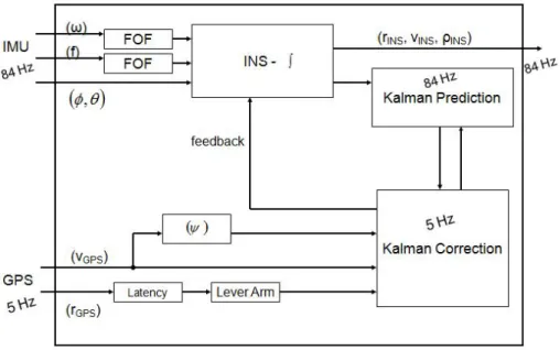
3.4 LARA-3D localization functionality . . . 74
3.5 LARA-3D experimental results and analysis. . . 75
3.6 Post-mission processing techniques . . . 79
3.6.1 Kalman smoother . . . 81
3.6.2 A spline-based smoothing approach. . . 83
3.7 A numerical trajectory smoothing approach . . . 86
3.7.1 Altitude jump detection and correction . . . 86
3.7.2 Spline-based trajectory smoothing in 2D . . . 89
3.7.3 Address yaw problems . . . 93
3.7.4 Smoothing using half quadratic filtering . . . 93
3.7.5 Re-computation of X, Y from the smoothed yaw . . . 95
3.8 LARA-3D post-mission processing improvements . . . 96
3.9 Conclusion . . . 98
4 Preface to perception-based localization 103 4.1 Introduction. . . 103
4.2 Laser scanners . . . 104 10
CONTENTS
4.3 Simultaneous Localization and Mapping (SLAM) . . . 106
4.4 Solutions to SLAM problem and their limitations . . . 106
4.5 Prelude to our laser odometry approach . . . 111
4.6 Conclusion . . . 112
5 Planar landmark extraction 115 5.1 Introduction. . . 115
5.2 Motivation . . . 116
5.3 2D laser scanner-based system design. . . 117
5.3.1 Justification: usage of a pair of parallel scanners . . . 118
5.3.2 Justification: inclination of the scanning planes . . . 119
5.3.3 Justification: two isoclinal laser pairs. . . 120
5.4 Algorithms for the extraction of planar patches . . . 121
5.4.1 Input - 2D laser scanner profiles . . . 121
5.4.2 Line extraction . . . 125
5.4.3 Line correlation . . . 133
5.4.4 Plane fitting . . . 136
5.5 Experimentations and results . . . 137
5.5.1 Test performed using simulated data . . . 137
5.5.2 Test performed using real data . . . 140
5.6 Conclusion . . . 141
6 Laser odometry using planar landmarks 149 6.1 Introduction. . . 150
6.2 Motivation . . . 151 11
6.3 Laser odometery . . . 152
6.4 Improved laser odometery . . . 153
6.5 Data Association . . . 155
6.5.1 Lenient Data Association . . . 160
6.5.2 Strict Data Association . . . 166
6.6 Transformation resolution . . . 169
6.6.1 Splitting the transformation . . . 169
6.6.2 3D Rotation . . . 171
6.6.3 3D Translation . . . 175
6.6.4 2D Translation . . . 177
6.7 Addressing multiple associations . . . 181
6.7.1 Optimal candidate selection algorithms . . . 182
6.7.2 Optimal rotation computation . . . 185
6.7.3 Optimal translation computation . . . 188
6.7.4 Mean-based translation computation . . . 189
6.8 Trajectory estimation . . . 191
6.9 Conclusion . . . 192
7 Experiments, analysis and improvements 195 7.1 Introduction. . . 195 7.2 Implementation . . . 196 7.2.1 Assumptions . . . 196 7.2.2 Algorithm . . . 200 7.2.3 Configuration parameters . . . 202 12
CONTENTS
7.3 Experimentations . . . 203
7.3.1 Datasets . . . 204
7.3.2 Results and analysis . . . 206
7.4 A possible improvement . . . 223
7.4.1 Delayed map update . . . 223
7.5 Conclusion . . . 224 8 Conclusion 231 8.1 Summary . . . 231 8.2 Future extensions . . . 233 8.3 Epilogue . . . 235 Publications 237
A GNSS receiver analysis in mid urban environment 239
B Differential GPS analysis 241
C Effect of simulated GPS loss on pose 245
D Analysis of a low cost navigation sensor 247
E Gyro bias identification in real time 251
Bibliography 253
List of Figures
1.1 Three functional levels in localization. . . 28
1.2 Overview of the dissertation . . . 32
2.1 Mobile Mapping Systems . . . 37
2.2 Comparison of results of a land-based and an aerial MMS . . . 40
2.3 Elements of a mobile mapping system (modified version of [El-Sheimy 96]) 51 2.4 Mobile Mapping Systems - primary functionalities . . . 52
2.5 Localization process . . . 53
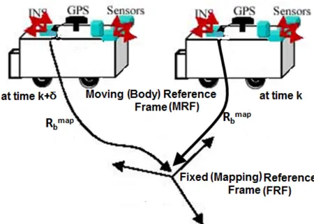
2.6 Georeferencing (modified version, original from [Manandhar 00]) . . . . 55
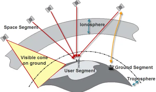
2.7 GNSS overall functionality. . . 57
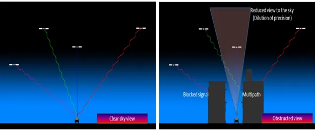
2.8 Computing position using GNSS receivers in open and obstructed envi-ronments . . . 59
2.9 GPS error correction using a fixed base station . . . 60
2.10 Description of inertial sensor . . . 62
2.11 Gimbaled and strapdown INS . . . 63
2.12 Two types of odometers . . . 66
2.13 Odometer - linear velocity computation . . . 66
3.1 LARA-3D prototype mobile mapping platform . . . 73 15
3.2 LARA-3D input sensors . . . 74
3.3 LARA-3D process of 3D point cloud generation . . . 75
3.4 LARA-3D resulting 3D maps . . . 76
3.5 LARA-3D system architecture [Goulette 06]. . . 76
3.6 LARA-3D localization architecture . . . 77
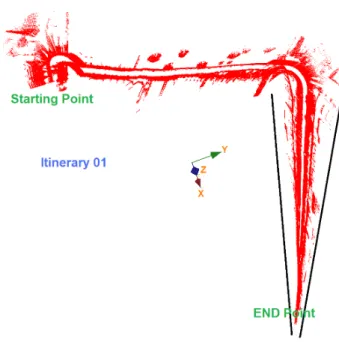
3.7 Two itineraries used for data acquisition with LARA-3D, from rural and urban areas. . . 77
3.8 Observed problem of yaw drift . . . 78
3.9 Observed problem of altitude jump . . . 78
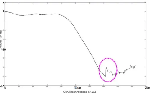
3.10 Altitude vs. curvilinear abscissa. . . 79
3.11 Altitude jump in relation to GPS fix perturbations . . . 80
3.12 Forward and backward prediction and smoothing errors . . . 82
3.13 Effect of cubic spline smoothing on GPS estimated trajectory . . . 85
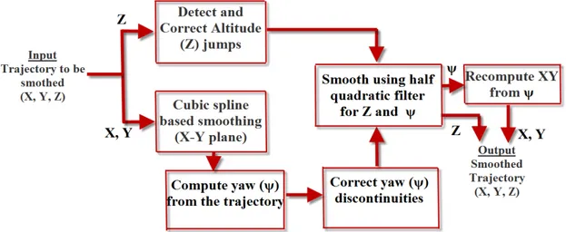
3.14 Our automated post-mission processing technique. . . 86
3.15 Altitude jump detection . . . 88
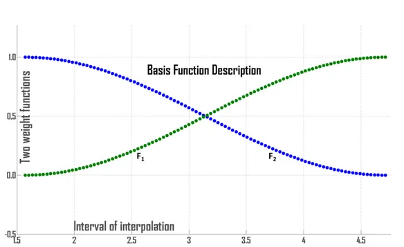
3.16 Basis functions for altitude jump correction . . . 91
3.17 Corrected altitude jumps . . . 91
3.18 Altitude jump correction a close view . . . 92
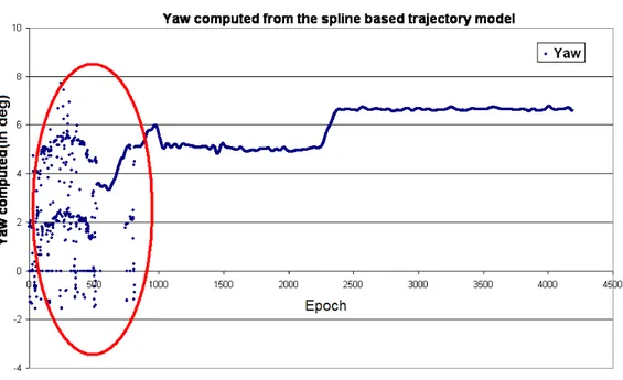
3.19 Yaw computation from the trajectory . . . 92
3.20 Deduced yaw from the smoothed planimetric trajectory . . . 94
3.21 Altitude signal improvement by using half quadratic filtering . . . 96
3.22 Heading drift and discontinuities corrected point cloud . . . 97
3.23 Google street viewer image of the scene with yaw problems . . . 98
3.24 Ground check on the point clouds prior and after post processing . . . . 99 16
LIST OF FIGURES
3.25 Altitude jump corrected point cloud . . . 100
4.1 2D and 3D laser scanners in robotics . . . 105
4.2 Applications of GPS less navigation (using SLAM) . . . 107
4.3 Feature based approach for SLAM problem . . . 108
4.4 Scan correlation an optimization approach to SLAM . . . 109
4.5 3D scans and the extracted planar features . . . 110
4.6 Correlating two 3D point clouds . . . 110
5.1 2D laser scanner based system design. . . 118
5.2 Justification for the parallel lasers . . . 119
5.3 Benefit of increased temporal observability of landmarks . . . 121
5.4 Planar landmark extraction process. . . 123
5.5 Laser scan profile description . . . 124
5.6 Coordinate transforms . . . 126
5.7 Demonstration of recursive segmentation algorithm (chord or IEPF) . . 129
5.8 Result of the segmentation process . . . 130
5.9 Relationship between distance to the plane, precision of laser range mea-surements, and the number of points per plane . . . 132
5.10 Line correlation conditions . . . 134
5.11 An urban test scene - generated using SIVIC . . . 138
5.12 Planar patch extraction with simulated data: validation using SIVIC . . 143
5.13 Indoor test platform for planar patch extraction. . . 144
5.14 Results of the planar patch extraction using real data . . . 145
6.1 Pose determination using geometrical properties of landmarks . . . 153 17
6.2 Divide & Conquer approach for pose computation using planar landmarks154
6.3 Description of Data Association process . . . 156
6.4 Data Association - absolute vs. relative constraints . . . 158
6.5 Euclidean vs. Mahalanobis distance . . . 159
6.6 Data Association in a moving reference frame . . . 161
6.7 Relative constraint - dihedral angle . . . 162
6.8 Applying absolute constraints to reduce ambiguities . . . 165
6.9 Ambiguity resolution - voting steps . . . 168
6.10 Splitting transformation: a rotation and a translation . . . 170
6.11 Rotation resolution using planes . . . 172
6.12 3D and 2D views of the observed planar patches at a given epoch . . . . 178
6.13 Projected planar landmarks and their intersecting points in 2D, in both fixed and moving reference frames . . . 179
6.14 Translation computation from rotation compensated intersection points 180 6.15 Translation computation by center of gravity method. . . 191
7.1 Partial vision of a planar surface . . . 199
7.2 Scenario with known trajectory - top view . . . 205
7.3 A cubic world test data scene from SIVIC . . . 206
7.4 Trajectories with four different noise levels . . . 208
7.5 Effect of noise on the rotation rate estimation . . . 209
7.6 Effect of noise on the translation vector estimation . . . 210
7.7 Noise statistics for all the 5 degrees of freedom . . . 211
7.8 Ambiguous planar associations . . . 212
7.9 Generated trajectory comparison between OCSC and WOCSC methods 213
LIST OF FIGURES
7.10 Importance of strict data association . . . 214
7.11 Importance of appearance test to resolve ambiguities . . . 216
7.12 Trajectory with vehicle speed of ∼ 10 kmph . . . 217
7.13 3DOF rotation rate errors for the estimated trajectory, for a vehicle driven at ∼ 10 kmph . . . 218
7.14 2DOF translation errors for the estimated trajectory, for a vehicle driven at ∼ 10 kmph . . . 220
7.15 Trajectory estimation improvement using delayed data association . . . 221
7.16 Improvement in 3DOF rotation rates with delayed association . . . 222
7.17 Improvement in 2DOF translation rates with delayed association . . . . 226
7.18 Proposed delayed map update method, conditions for the transition of trust indicators . . . 227
A.1 Test results in urban areas using a GNSS receiver . . . 240
B.1 Improving GPS position fix by using a DGPS . . . 244
C.1 Effect of GPS data loss on trajectory estimation . . . 246
D.1 Low-cost integrated MEMS sensor . . . 247
D.2 Stationary platform test for the MEMS sensor. . . 249
D.3 MEMS sensor test on a moving platform . . . 250
List of Tables
1 Abbreviations . . . 23
2.1 Existing Mobile Mapping Systems . . . 41
2.2 GPS error budget. . . 58
2.3 INS quality vs. cost classification . . . 64
5.1 Different forms of data discontinuities . . . 127
5.2 Confidence indicator for the line segments . . . 132
5.3 Plane extraction: configuration parameters, used in the SIVIC environment139
5.4 Plane extraction: configuration parameters for real data . . . 140
7.1 Input laser scanner configurations. . . 202
7.2 Algorithmic parameters . . . 203
Table 1: Abbreviations
Acronyms Expansion
ABA Adaptive Breakpoint Algorithm
ABS Anti-lock Breaking System
AR Auto Regression
C/A Coarse Acquisition
CCDA Combined Constraint Data Association
Cog Center of gravity
DA Data Association
D&C Divide and Conquer
DGPS Differential GPS
DMU Dynamic Measurement Unit
DOD Department of Defense
DOF Degrees of Freedom
DOP Dilution Of Precision
DR Dead Reckoning
DSM Digital Surface Model
DTMO Detection and Tracking of Moving Objects
ECEF Earth Centered Earth Fixed
EGNOS European Geo Stationary Navigation Overlay Service
EKF Extended Kalman Filter
EM Expectation Maximization
ENU East, North, Up
ESOC European Space Operations Center
FOF First Order Filter
FRF Fixed Reference Frame
GBAS Ground Based Augmentation Systems
GNSS Global Navigation Satellite System
GPS Global Positioning System
HISS Hybrid Inertial Survey System
HMM Hidden Markov Model
ICC Instantaneous Center of Curvature
IDC Iterative Dual Correspondence
ICP Iterative Closest Point
ICR Instantaneous center of rotation
IEPF Iterative End Point Fit
IGS International GPS Service
IMU Inertial Measurement Unit
INS Inertial Navigation System
ISA Inertial Sensor Assembly
Continued on Next Page. . .
Acronyms Expansion
LASER Light Amplification by Stimulated Emission of Radiation
LDA Lenient Data Association
LIDAR Light Detection And Ranging
LRF Laser Reference Frame
LTP Local Tangent Plane
MEMS Micro Electro Mechanical Systems
MEO Medium Earth Orbit
MHT Multiple Hypothesis Tracking
MMS Mobile Mapping System
MRF Moving (Mapping) Reference Frame
NED North, East Down
NIS Normalized Innovation Squared
OCSC Optimal Candidate Selection by Consensus
ORF Object Reference Frame
POS Position and Orientation System
POS/LV Position and Orientation System for Land Vehicles
PRN Pseudo Random Noise
RANSAC RANdom SAmple Consensus
RLG Ring Laser Gyroscope
RTK Real Time Kinematic
SA Selective Availability
SBAS Space Based Augmentation Systems
SDA Strict Data Association
SHT Single Hypothesis Tracking
SLAM Simultaneous Localization and Mapping
SLAMMOT Simultaneous Localization, Mapping and Moving Object Tracking
UKF Unscented Kalman Filter
ULEE User Local Environment Errors
VRF Vehicle Reference Frame
VRS Virtual Reference Station
WGS84 World Geodetic System
WOCSC Weighted Optimal Candidate Selection by Consensus
Chapitre 1
Introduction
Ce chapitre pr´esente le contexte de la th`ese, son domaine d’applications, ses objectifs et les contraintes associ´ees ; il comporte ´egalement un bref aper¸cu de l’ensemble de l’´etude. Ce chapitre pr´esente l’ensemble des contributions scientifiques originales de cette th`ese. Cette recherche est men´ee avec la collaboration de l’´equipe d´edi´ee au syst`eme de cartographie mobile (Mobile Mapping System - MMS) dans le laboratoire de robotique (CAOR) de l’´Ecole des Mines de Paris.Le contexte de la recherche est de fournir des outils compl´ementaires pour la locali-sation d’un syst`eme MMS terrestre. Tous ces syst`emes utilisent des r´ecepteurs GPS et des centrales `a inertie (Inertial Measurement Units - IMU), pour d´eterminer la position et l’orientation (pose) de la plateforme mobile dans l’espace `a 3 dimensions. Les limi-tations actuelles des MMS sont dues aux insuffisances de ces capteurs : Les r´ecepteurs GPS peuvent subir une d´egradation de la qualit´e du signal re¸cu, dans un environne-ment qui masque une partie du ciel ; les informations fournies par les centrales `a inertie pr´esentent souvent des d´ecalages non corrig´es, ces d´ecalages se traduisent par des d´erives dans la position estim´ee (une centrale de bonne qualit´e est tr`es couteuse, de l’ordre d’une centaine de milliers d’euros).
La th`ese porte sur deux aspects : d’une part, une technique de post-traitement (lissage des r´esultats) permet de corriger certaines erreurs triviales li´ees aux limitations des capteurs ; d’autre part, les scanners `a laser, qui sont utilis´es pour cr´eer les donn´ees cartographiques, permettent ´egalement d’aider `a la localisation du v´ehicule.
Le chapitre 2 pr´esente l’´etat de l’art des MMS. Le chapitre 3 illustre les limitations des MMS et pr´esente une approche de post-traitement. La m´ethode qui utilise les scanners `a laser dans la localisation est d´ecrite en d´etail dans les chapitres 4 `a 7. Le chapitre 8 conclut cette th`ese.
Chapter 1
Introduction
Contents 1.1 Context . . . 27 1.2 Scope. . . 28 1.3 Main contributions . . . 291.4 Overview of the dissertation . . . 31
1.1
Context
This research is done in collaboration with the dedicated Mobile Mapping Systems (MMS) team in the Robotics lab (CAOR) of Ecole des Mines de Paris. The MMS team is involved in projects: VIZIR/DIVAS (under the program SARI) and TERRA Numerica (under the program Cap Digital). The LARA-3D, a land-based MMS prototype platform being developed by the MMS team is used for providing the digitalized 3D terrestrial maps for these projects. The maps are created using a laser scanner and represented in the form of 3D point clouds. At some instants, the quality of the maps degrades, when the mobile mapping platform (a land-based vehicle) faces difficulties to localize itself with respect to the mapping reference frame. This is the most common problem for many MMS around the world. The thesis, therefore, focuses on improving the localization ability of a land-based laser MMS.
Localization is the process that unambiguously defines one’s position and orientation (i.e. pose) in space with respect to a reference, at a given time. Self localization is needed in several fields such as autonomous navigation, search and rescue, and mobile mapping, the domain of focus in this thesis. Mobile Mapping Systems (MMS) requires continuous pose estimation of the moving mapping platform, during the data acquisition phase.
MMS reduce the incurred cost and acquisition time compared to the conven-tional mapping methods. The technology dates back to the early 1990s, where the first MMS GPSVan is designed and implemented at Ohio State University, USA [Grejner-Brzezinska 02].
The map quality generated through this technique is however very sensitive to the localization accuracy. Any error in the computed pose, transforms into errors in the map. Therefore, this study focuses on improving the localization functionality of a mapping system.
1.2
Scope
The localization functionality has three principal components shown in figure 1.1: in-put sensors which directly or indirectly measure the pose components, data fusion, also called as sensor integration schemes, consisting of algorithms to combine one or more independent sensor measurements to estimate the optimal pose, and the post mission processing, consisting of any additional off-line algorithms applied to improve the ob-tained results. Among these, input sensors are the most critical component for the localization.
Figure 1.1: Three functional levels in localization: the data flow is sequential and shown in red, where each of the three blocks can contribute to the pose estimation
1.3. MAIN CONTRIBUTIONS 29
(GNSS) receivers (in most context it is just the GPS), and inertial navigation using an Inertial Measuring Units (IMU), are used as the common input sensors. Although each of these technologies can, in principle, determine both position and orientation, they are usually integrated in such a way that the GPS receiver is the main position sensor, while the IMU is the main orientation sensor [Schwarz 04]. However, dependency on GPS receivers, which require satellite signal for positioning, limits the MMS to outdoor mapping applications. Most of the existing MMS suffer when the GPS-based positioning accuracy degrades. This problem arises often in the most frequently mapped urban areas, due to the presence of tall manmade structures, masking the clear view to the sky. Due to drift errors in the computed pose and the high cost versus quality ratio of the IMU, an alternative method for localization is desirable for many mapping applications. In the context of this thesis, multiple sensors (items 1) and data fusion (items 2) of figure 1.1, were the focus of an earlier re-search done in the MMS team [Abuhadrous 05], and several other works [El-Sheimy 96], [Skaloud 99], [Manandhar 00], [Schultz 06], [Chiang 05], [Shi 08]. All these works focus on combining multi-sensor data, to better estimate the pose. The multi-sensors (items 1) are often limited to GPS, IMU (both 3D pose), odometer and compasses (2D or 1D pose). This thesis focuses on improving localization of a mobile mapping system by an alternative way to compute 3D pose and a set of algorithms (items 1 and item 3 ).
Our research addresses the shortcomings of 3D pose sensors (GPS and IMU), by proposing solutions adhering to two main objectives:
• Pose information in 3D space - Solution capable of computing 3D pose. • Complementary to current 3D localization - Solution to overcome the
limi-tations of the two commonly used 3D pose sensors. i.e. to minimize the effects of degraded GPS signal and IMU measurement drifts, on the computed pose of the mobile mapping platform.
Additionally, we apply a cost constraint, which limits the selection of the improve-ment axis to methods, incurring only a marginal increase to the cost. Therefore, solu-tions such as a good quality IMU (navigation grade), which costs more than a hundred thousand Euros are not considered.
1.3
Main contributions
The thesis proposes two solutions. First, an improvement of the current localization technique based on GPS&IMU, and, the second, developing a new localization method, independent of these localization sensors.
After analyzing the effect of GPS signal quality on the pose of an MMS, a post mission processing method is proposed to correct these errors in the trajectory. This is achieved by an automated smoothing approach, which we designed and implemented to correct the slowly varying altitude errors caused by the inaccurate GPS signal. Combin-ing this method with a spline-based trajectory smoothCombin-ing, most of the apparent errors in the trajectory is corrected. This approach however needs further improvements to tackle slowly varying sensor errors.
Perception sensors such as laser scanners and cameras, are integral part of MMS, but used mainly for mapping. We propose a novel geometrical localization approach, based on laser scanner measurements. For the perception to work, mapping environment must contain objects and obstacles, as opposed to the GPS receivers, whose solutions degrade in such situations. Additionally, this approach can contribute to the reduction in the cost of the MMS, since the localization and the mapping can be achieved by the same set of sensors.
Perception sensor-based localization is presently used with the technology of Simul-taneous Localization and Mapping (SLAM). SLAM approaches are mainly used for the navigation of robots in the indoor environments, where GPS positioning (GPS fix) is unavailable. The feature-based SLAM, detects and localizes the landmarks on a map, while simultaneously estimating the pose of the robot, from where the landmarks are ob-served [Durrant-Whyte 06], [Bailey 06]. Most of the existing SLAM approaches resolve robot pose in 2D space.
In this thesis, we use planar features as landmarks, not only because, they occur frequently in manmade environments and easier to extract, but also, their geometrical properties can help determine the 3D pose information. We choose dead reckoning, the method used in odometry, to compute the relative pose between two set of observed planar landmarks. Therefore, this approach can be called as a laser odometry. This approach, helps reduce the landmark association (called as Data Association or DA: association of new observation of landmarks with the already observed ones) failures typically observed in most SLAM approaches). These are caused by the growing uncer-tainties in the mapped landmark locations due to the unceruncer-tainties in the robot pose.
For a laser odometry to function, a set of landmarks need to be extracted in such a short time that the deformation due to movement of the robot remains insignificant. To compute an independent pose from other sensors, the features need to be extracted from raw scans, rather than the one’s referred in a map (georeferencing). This way of planar extraction is not seen in any literature before. Therefore, we propose a new system design and the chain of algorithms, tailor made to extract the planar features from a given pose of the vehicle, using a 2D laser scanner arrangement.
The 3D pose problem (transformation computation) has 6 degrees of freedom (6DOF), which is complex to resolve due to the additional load of unknown Data
Associ-1.4. OVERVIEW OF THE DISSERTATION 31
ation. Optimization techniques and regression models are applied to solve this problem, however, they treat it as a single problem (transformation and DA) to solve. We propose a method to simplify this process, by applying a unique Divide and Conquer approach (D&C), which separates the Data Association and transformation computation in two, and further splits the two process in two. The sequential processes are: a Lenient Data Association or LDA, rotation resolution, a Strict Data Association or SDA (optional), and translation computation.
As the name suggests, LDA, is performed using a relaxed set of constraints, to compensate for all the unknowns related to transformation and DA. This implies, the resulting associations can be ambiguous. Therefore, a mean-based or least square-based methods unfit to resolve transformation from these associations, since the final result gets biased by the erroneous input associations. We propose a new Optimal Candi-date Selection with Consensus (OCSC) algorithm, and its weighted variant (WOCSC), which selects an optimal minimal set of association to compute the transformation. We demonstrate that, the algorithm effectively eliminates outliers, deals with noisy candi-dates, and resolves ambiguities. The transformation is estimated using the geometrical properties of planar landmarks by applying only WOCSC, or alternatively, at this stage, translation alone can be computed using a mean-based method with SDA.
Finally, we also propose our designed solution, termed as ”delyed map update”, to tackle drift errors (another common SLAM and odometry problem) in the integrated pose.
1.4
Overview of the dissertation
Figure 1.2gives the overall flow of this thesis.
Chapter 2: Overall view of the MMS, and the importance of localization for such systems is given here. Almost all MMS around the world, depend on GPS receivers and inertial sensors, for localization. We therefore, briefly look at their functionalities and limitations to understand the impact of their shortcomings on MMS.
Chapter 3: This chapter presents a post mission processing approach to correct the apparent errors in the trajectory, occurring due to the localization sensor limitations. This fully automated method corrects altitude jumps, and azimuth (yaw) anomalies in the trajectory. We present the results of this approach, using the 3D maps generated from the LARA-3D platform.
Chapter 4: The post mission processing described in chapter3can be improve ap-pearance of 3D maps, but insufficient for precise localizations, especially when the GPS signals are not available. Therefore, we explore the possibility of using the integrated mapping or perception sensors (e.g. laser scanners) of MMS for localization. This chap-ter briefly introduces the concept of perception-based localization, and the technique of Simultaneous Localization and Mapping (SLAM). This leads to the motivation to our
Figure 1.2: Overview of the thesis dissertation.
work on ”laser odometry using planar landmarks”.
Chapter 5: This chapter covers the first and important step of the laser odometry introduced in chapter 4. Quick acquisition of planar feature information is a key to extract the landmarks properties, without deforming them due to the motion of the sensor platform. Planar landmark extraction using a specific arrangement of 2D laser scanners are detailed in this chapter. We present the system design, algorithms, and the obtained results.
Chapter 6: This chapter describes our D&C approach, to resolve the complex 3D localization, using planar landmarks, possibly extracted using the process explained in chapter4. The method of Data Association (both LDA and SDA), and transformation computation using time invariant geometrical properties of the landmarks is explained. Theories of the OCSC and WOCSC are given, with their application to transformation computation.
Chapter 7: This covers the implementation details of the algorithms and the meth-ods presented in chapter 6. Following that, the experimentation setups along with the algorithm validation results and analysis are presented. These results lead us to present a novel delayed map update method, which addresses the drift errors in the integrated pose, observed in most SLAM approaches.
Chapter 8: This chapter concludes the thesis, highlighting the possible extensions to this work.
Chapitre 2
Les syst`
emes de cartographie
mobiles
Ce chapitre pr´esente l’´etat de l’art des syst`emes de cartographie mobiles (MMS). Un MMS comporte une plateforme mobile, ´equip´ee de capteurs qui assurent sa localisation et permettent la cartographie de son environnement.Les cartes num´eriques sont g´en´er´ees `a partir des propri´et´es de l’environnement, pro-pri´et´es mises en relation avec la position courante du v´ehicule, position qui est es-tim´ee par le sous syst`eme de localisation. Ce processus de mise en relation est appel´e g´eor´ef´erencement. Toute erreur de localisation se traduit par une erreur dans les cartes num´eriques g´en´er´ees.
La plupart des MMS sont utilis´es en ext´erieur, une estimation correcte de la position 3D de la plateforme (6 degr´es de libert´e) est donc essentielle.Notre analyse de pr`es d’une quarantaine de MMS a mis en ´evidence que localisation et cartographie sont le plus souvent effectu´ees s´epar´ement, par des capteurs d´edi´es. Tous ces syst`emes utilisent des r´ecepteurs GPS et des centrales `a inertie pour estimer leur position 3D.
Ces deux cat´egories de capteurs de localisation sont `a l’origine de la principale li-mitation des syst`emes mobiles de cartographie actuels. Les r´ecepteurs GPS perdent de leur pr´ecision dans un environnement o`u une partie de l’espace est masqu´e par des obs-tacles tels que les constructions, la v´eg´etation, etc. Ces obsobs-tacles provoquent de plus des r´eflexions multiples du signal radio, qui accentuant encore la d´egradation de la pr´ecision de l’estimation de position. Les centrales `a inertie sont principalement uti-lis´ees pour calculer l’orientation d’un mobile ; elles permettent ´egalement de compenser une d´egradation du signal GPS sur de courtes p´eriodes. La position calcul´ee `a partir des donn´ees d’une centrale `a inertie est sujette `a des d´erives, et une centrale de bonne qualit´e a un cout ´elev´e.
probl`eme dans les environnements urbains o`u les immeubles peuvent cr´eer des couloirs ´etroits.
Chapter 2
Outdoor and Indoor Mapping
Systems
Contents2.1 Introduction . . . 35
2.2 Mobile Mapping Systems. . . 36
2.3 Applications . . . 36 2.4 Generated 3D maps . . . 39 2.5 Existing Systems . . . 39 2.6 Functional blocks . . . 51 2.6.1 Localization process . . . 51 2.6.2 Direct georeferencing . . . 54
2.7 Importance of localization for a Mobile Mapping System . 55
2.8 Localization sensors and their limitations . . . 56
2.8.1 Global Navigation Satellite System (GNSS) receivers . . . 56
2.8.2 Inertial Measurement Unit & Inertial Navigation System. . . . 61
2.8.3 Odometer . . . 65
2.9 Conclusion . . . 68
2.1
Introduction
This chapter intends to give an overall view of the Mobile Mapping Systems (MMS), and their current limitations. We identified nearly forty MMS, developed both academically and commercially, around the world.
MMS have two main functionalities: localization and georeferencing (or mapping), performed by the dedicated set of sensors. Localization estimates the pose of the mobile vehicle using which the georeferencing creates the maps from the perception sensor measurements.
Unless specified, in this thesis, MMS means the land-based MMS, with a sensor equipped land vehicle or robot, as the mobile mapping platform.
The flow of this chapter is organized as follows:
Sections 2.2, 2.3 and 2.4, presents the Mobile Mapping Systems (MMS), their ap-plications and typical results. The list of nearly 40 MMS that are studied is given in section 2.5 with their sensor configurations. The functional structure of MMS is given in section2.6, and the importance of localization under section 2.7. Then an overview of the most commonly used localization sensors, their functionalities and the limitations are listed in section2.8. Section2.9 concludes the chapter.
2.2
Mobile Mapping Systems (MMS)
In comparison to the traditional mapping techniques, Mobile Mapping Systems (MMS) provide a time efficient mean to digitize the surrounding environments. The complete definition of such a system is:
”A Mobile Mapping System can be defined as a moving platform, upon which mul-tiple sensor/measurement systems have been integrated to provide, three-dimensional, near-continuous positioning of both the platform and simultaneously collected geospa-tial data, with no or limited ground control using single or multiple GPS base sta-tions” [Grejner-Brzezinska 02].
The development of such systems become possible, as the USA government made the GPS signal available to the civilian community [Manandhar 00].
Four different MMS platform configurations are shown in figure 2.1.
2.3
Applications
The latest developments in surveying and mobile mapping technologies open new av-enues for acquisition, update, fast and near real time online data processing [Zhang 03]. With the continuous growth of urban centers on world-wide scale, the demand of city planners for up-to-date information is increasing at a rapid rate. Along with these de-velopments, comes the need of improving the infrastructures as well. This has led to the
2.3. APPLICATIONS 37
(a) VISAT van - land-based [El-Sheimy 96] (b) Quadbike, Street mapper - land-based [Hunter 06]
(c) HELIMAP - airborne [Skaloud 05] (d) Google Trike - land-based [Google. 10]
establishment of spatially-referenced Geographic Information Systems (GIS) for a vari-ety of applications [El-Sheimy 96]. Due to the growth and rapid changes in the cities, it is essential to rapidly update the GIS at a reasonable cost. Therefore, mobile mapping technology becomes an essential method for acquiring and characterizing information for vital infrastructure management.
The accurate 3D terrain models contribute to a number of applications such as mapping, planning, organizing, and for various other studies. Due to the increasing popularity of this technology, a number of industrial solutions have emerged along with a vast number of research projects undertaken around the world. Improved solutions and reduced operating cost has helped in identifying several new applications for the MMS which are exhaustively presented below:
• City modeling - 3D realistic modeling of the urban environment helps studies of architecture and infrastructure and provides a tool for city planning. This application is described in [Grinstead 05] and [Hunter 06].
• Feature extraction - The resulting 3D models are used for extracting objects of interest and features from the mapped scene, triggering several automated stud-ies and analysis [Manandhar 01]. Each element can be tagged individually as a building, a monument, or a street, helping to construct a 3D GIS. GIS contribute to the growth of applications like Location Based Services (LBS) [Hwang 03]. • Analysis and improvement of road infrastructure - Applications that
re-quire generated 3D models include surveillance and road infrastructure analysis tools, geometric studies (infrastructure) of the road to determine the visibility etc. These studies can help validate the speed limits and identify the need of new sign boards. The feature extraction techniques are used to automate the analysis of road signage and delineation [McLoughlin 08]. These applications are mentioned in several articles [Gilli´eron 01], [Ooishi 04], [Grinstead 05], [Yu 07].
• Automatic productive operations - Highway asset measurements, indivisible abnormal load route planning, or recording accident scenes - to shorten the time before the road can be cleared [Hunter 06].
• Precision agriculture - This term refers to within-field management of crops using an information and technology-based system. ”It basically means adding the right amount of treatment, at the right time and the right location, within a field-that’s the precision part”. [Shaikh 03].
• Virtual reality - The 3D map-based realistic models are used in virtual real-ity applications, including driving simulators, robotic path planning, terrain-fire interactions etc. [Grinstead 05], [Hwang 03] or a mere entertaining way such as virtual tourism, and video games etc. [Goulette 06].
2.4. GENERATED 3D MAPS 39
A real time map generation is desirable for most of these applications but its not a necessity. Only a few mapping applications such as military and emergency response systems require real time performances [Li 97]. For all the others, only the data acqui-sition requires time critical performance, where the sensor measurements needs to be precisely timestamped for further processing.
Due to the limitations of GPS receivers, all these applications rely on outdoor ac-quisitions. The availability of a reliable GPS independent pose information can open up a new set of applications for MMS, in GPS signal denied environments such as indoors.
2.4
Generated 3D maps
The 3D maps generated depends on the type of the moving mapping platform and the mapping (or perception) sensors.
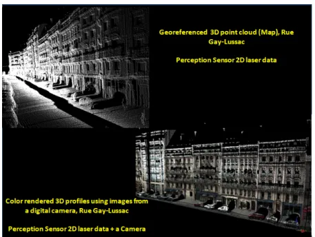
The moving mapping platform can be of three principle types: land-based, aerial and marine, however, the first two are the most frequently used. This thesis focuses only on a land-based MMS. This type of MMS is potentially more efficient in data capturing, for numerical modeling and/or visualization in support of decision making, and also for filling the void between static terrestrial and mobile airborne laser scanning [Barber 08]. The obtained results using typical MMS are demonstrated in figure 2.2, where a comparison is drawn between the 3D models of the same urban scene, constructed using a land-based and an aerial MMS. The figure shows Rue Boulevard Saint Michel in Paris, highlighting Ecole des Mines de Paris (Mines ParisTech).
In this figure, the land-based MMS LARA-3D uses a laser scanner as the perception sensor, whereas the airborne MMS uses digital camera. The terrestrial model has more realistic information about the architecture and fine details compared to the airborne system, which is constructed by mathematical models using 2D orthophotos and altitude information.
2.5
Existing Mobile Mapping Systems
At present, there are at least 40 different land-based MMS solutions available around the world, with USA having 9, Japan with 4 and France, Germany Italy and Canada all with at least 3 each. MMS solutions are now even being developed commercially as turnkey projects in different countries.
sen-(a) Result of a land-based MMS (LARA-3D ) (b) Processed aerial MMS (Bati-3D, IGN)
Figure 2.2: Comparison of results of a land-based (a) and an aerial MMS (b), both highlighting Ecole des Mines de Paris (Mines ParisTech), in red
sors, which aid in the trajectory estimation of the mapping platform, and mapping (or perception) sensors, used for digitizing the environment. In most MMS, they contribute only to their dedicated functionality, i.e. a localization sensor is not used for mapping, and vice versa. The mapping platform embed these sensors. These two types of sensor information is combined together by the georeferencing, to produce the maps of the environment.
In table2.1, an attempt is made to list and categorize most of the presently available MMS systems. Several sources of inputs ([Barber 08], [Ellum 02] and individual articles of the developers of MMS) are taken to accumulate this information. At times different sources had different information such as number of sensors, type of used sensors and the name of the MMS etc. We believe this is because, the MMS are evolved over a period of time and used in different configurations for various tests. The field ”year” is just an indicative, mostly taken from the published article dates.
2.5. EXISTING SYSTEMS 41 T able 2.1: Existing Mobil e Mapping Systems N Name of the system Coun try Appro x Y ear Univ ersit y or Compan y POS -Sensors P erception Sensors 1 GPS- VanTM USA 1991 Cen ter for Map -ping Ohio State Univ ersit y Kinematic Differen tial Carrier phase Range data (GPS R TK) and a Dead Rec koning Sys-tem (DRS). DRS included Three axis re fe re n ce system (TRS-Gyros) and wheel sen-sors (o dometer) CCD Cameras (Stereo PULNiX), VHS Cameras 2 GIM USA 1994 Na vsys GPS, Lo w cost IMU CCD Camera, VHS Cam-era 3 Kinematic Surv ey Sys-tem (KiSS) German y 1995 In tegrierte Kine-matisc he V ermes-sung (IKV), Uni-versit y of Munic h GPS (No vatel 95 1R), IMU (Litton LN-83), Odometer(Datron Dls-1), Barometer(Setra 470), Inclinometer(HL-Planar), Compass Multiple CCD Cameras (Stereo PULNiX TM 9700), VHS Cameras (1Son y VX 1E VHS) 4 Car-Driv en Surv ey Sys-tem (CDSS) German y 1998 Geo datisc hes In-stitut Aac hen C/A Co de GPS (T rim ble 4000 Ssi),Odometer, Barometer (SESTRA 470) 2 CCD Cameras (PUL-Nix), 2 Umatik VHS Con tin ued on Next P age .. .
T able 2.1 – con tin ued from previous page N Name of the system Coun try Appro x Y ear Univ ersit y or Compan y POS -Sensors P erception Sensors 5 WUMMS China 1999 W uhan Univ er-sit y Pseudorange measureme n t GPS 3 mono chr om e CCD Cam-era, Laser Range Finder 6 Mobile Road Mapping System or
(Mobiles Straßen Erfassungs System) (MoSES)
German y 2001 In tegrierte Kine-matisc he V ermes-sung (IKV), Uni-versit y of Munic h GPS -Na vigation grade IMU,(APPLANIX POS/L V), Odometer(Datron Dls-1), Barometer(Setra 470), Inclinometer(HL-Planar) Multiple CCD Cameras (Stereo P UL Ni X TM 9700), VHS Cameras (1Son y VX 1E VHS) (p ossible laser sc an ners ) 7 NAIST Japan 2002 Adv anced In te lli-gence Lab oratory NARA Institute of Science and T ec hnology GPS, IMU CCD Camera and Las er Scanner (Riegl LMS-Z360) 8 LD2000-R China 2005 Leador Corp Started in 1999 Dual F requency Carrier phase measuremen ts (GPS R TK), INS, Compass Not Disclosed Con tin ued on Next P age .. .
2.5. EXISTING SYSTEMS 43 T able 2. 1 – con tin ued from previous page N Name of the system Coun try Appro x Y ear Univ ersit y or Compan y POS -Sensors P erception Sensors 9 INSA Stras-b ourg F rance 2005 Lab oratory of MAP P A GE (MAP Pho-togrammetrie Arc hitecturale et GEoma-tique)(National Institute of Ap -plied Sciences of Strasb ourg) INSA Strasb ourg GPS, INS 4 mono chrome CCD Cam-era, 1 Color VHS cam-era, T rim ble Laser (GX DR 200+) 10 Stanley – Automated Vehicle (not MMS) USA 2005 Stanford Uni-versit y Stanford Artificial In telli-gence Lab oratory Stanley’s GPS L1/L2/Omnistar HP , tw o GPS for compass, IMU, ABS 5 SICK laser range finders 11 4S-V an Korea 2006 Electronics and T elecomm unica-tions Researc h Institute (ETRI) GPS, IMU and DMI IMPERX CCD Cameras V GA-120, 2M30C, 4M15C SICK Laser scanner LMS 291 12 LARA 3D F rance 2004-05 Ecole des Mines P aris GPS (T rim ble A G 132), IMU (Crossb ow V G600) Lidar (IBEO), CCD C am-eras Con tin ued on Next P age .. .
T able 2.1 – con tin ued from previous page N Name of the system Coun try Appro x Y ear Univ ersit y or Compan y POS -Sensors P erception Sensors 13 NoName Japan 2006 W aseda Univ er-sit y, T oky o T rim ble BD950 and ANT ARIS ub ox (GPS), Mitsubishi Elec-tric (o dometer), CR OSSBO W AHRS400CC-100 INS, Japan Aviation Gyro Electronics JG-35FD (Gyro) Lidar an d Fish Ey e Cam-era 14 StreetMapp er England 2006 StreetMapp er is a join t ven-ture b et w een 3D L aser Mapping and the engineer-ing compan y IGI They w ork with Univ ersit y of NewCastle up on T yne GPS, IMU (T erraCon trol -IGI pro duct) 5 Riegl LMS-Q120 laser range finders 15 NoName Mala ysia 2006 Univ ersiti T eknologi Mala ysia T rim ble 4800 and Leica GPS System 500 (R TK) CCD Cameras Con tin ued on Next P age .. .
2.5. EXISTING SYSTEMS 45 T able 2. 1 – con tin ued from previous page N Name of the system Coun try Appro x Y ear Univ ersit y or Compan y POS -Sensors P erception Sensors 16 ON-SIGHT USA 2006 Adaptiv e Ma-chine T ec hn olo-gies (AMT) Started in 1984 GPS, Na v igation Grade IMU Ko dak DC290 and Canon S400 17 Cit yGRID Austria 2007 GeoData GPS and others (not disclosed) CCD C ameras, Laser range finders 18 Stereop olis F rance 2007 IGN Applanix Lidar, CCD Cameras 19
Automatic Road Analyzer (ARAN)
Canada 2000- 2008 F ugro-Roadw are Roadw are group acquired b y F ugro In tl (2008) ARAN R GPS and INS (SmartGeometrics) or Ap-planix POS L V CCD Camera and Laser Scanner 20 Video im-ages, INS system, GPS Satel-lite system (VISA T-V an) Canada 1993-94 1999 Geomatics Engi-neering Depart-men t Univ ersit y Calgary Dual F requency GPS (Ash tec h 12), Na vigation Grade IMU (Litton L TN 90-100), ABS, Digital magnetic compass/In-clinometer Stereo CCD 37 Ultr a sound Con tin ued on Next P age .. .
T able 2.1 – con tin ued from previous page N Name of the system Coun try Appro x Y ear Univ ersit y or Compan y POS -Sensors P erception Sensors 21 T ruc kMapTM (FLI Map) USA 1995 1996 John Chance Land Sur-veys/FUGR O DGPS or OTF-Kinematic (Le-cia MX 8614 Magellan Sys-tems’ ProMARK X-CP), Digi-tal Altitude Sensor 8 COCHU 4980 CCD Cameras, 4 Sup er VHS Cameras 22 GPSVision USA 1996 2006 Lamda T ec h Geo detic Qualit y Dual F re-quency GPS (T rim ble 7400), Na vigation Grade IMU (Litton LN-200), Lin ear Distance Mea-suring Unit Laser Range Finder 23 Unidade M´ov el de Map eamen to Digital (UUMD) Brazil 1999- 2005 S˜ ao P aulo State Univ ersit y (UN-ESP) Tw o GPS receiv ers, and a im-age frame sync hr onisation sys-tem 2 or 4 High Sp eed CCD Cameras 24 VLMS -V ehicle-Borne Laser Mapping System (VLMS) Japan 2000-04 Univ ersit y of T oky o Hybrid Inertial Surv ey System (HISS) (DGPS INS, Electronic Odometer) Three IBEO digital video cameras (Son y DSR 200A) Con tin ued on Next P age .. .
2.5. EXISTING SYSTEMS 47 T able 2. 1 – con tin ued from previous page N Name of the system Coun try Appro x Y ear Univ ersit y or Compan y POS -Sensors P erception Sensors 25 T ele A t-las Mobile Mapping System Belgium 2007 T ele A tlas GPS, INS, Odometer Laser Scanners -4 Line Cameras (CCD) -Fishey e lens from Sigma fl 8mm 26 Geosoft Video Sur-vey (GVS) Italy 2006 GeoSoft NMEA compatibile (GPS), CR OSSBO W (INS) ABS 4 Son y dfw V500 (CCD/VHS) 27 ScanV an Netherlands DelftT ec h Not disclosed Cyrax 2500 scanner 28 Data Ac-quisition Vehicle with Inertial and DGPS Equipmen t (D A VIDE) Italy GIO VE S rl GPS (T rim b le) INS (Systron Donner) Odometer Nik on E2 Stereo 5 VHS Con tin ued on Next P age .. .
T able 2.1 – con tin ued from previous page N Name of the system Coun try Appro x Y ear Univ ersit y or Compan y POS -Sensors P erception Sensors 29 Precise Iner-tial System for Land Use with GNSS Real Time In tegrated Multipur- pose (PIL-GRIM) also GIGI Italy Univ ersit y of T ri-est GEOLAB Applanix GPS -No vatel Mil-lenium + D AR C/DGPS real time system or EGNOS INS -Litton Italia (with LITEF, German y) Stereo CCD 30 GEOMOBIL (GEO V AN) Spain Catolun ya Insti-tute of Cartogra-phie GPS, IMU CCD Cameras, Lidar 31 VISIMIND Sw eden VISIMIND AB GPS (TRIMBLE 7400), Odometer, (Mo dulo SOM misura assetto : Italian) Cameras Con tin ued on Next P age .. .
2.5. EXISTING SYSTEMS 49 T able 2. 1 – con tin ued from previous page N Name of the system Coun try Appro x Y ear Univ ersit y or Compan y POS -Sensors P erception Sensors 32 Photobus Switzerland Geo detic En-gineering Lab-oratory Swiss F ederal Institute of T ec hnology EPFL 2 GPS R TK CCD Camera 33 Road Mea-suremen t Data Ac-quisition System (R OMD AS) New Zealand 2000 R OMD ASS GPS, Gyroscop e, Single or Duel Bump De te ctors, Dis-tance Sp eed Sensor Laser, Videos 34 NoName USA 2005 Univ ersit y of T enessee Differen tial R TK GPS, IMU, P ose from Video (PfV) High re solut ion video cameras, laser range finders 35 Segw ay Rob otic Mobilit y Platform (Segw ay RMP) USA Univ ersit y of Southern Califor-nia GPS (Garmin), IMU MicroS-train Laser range-finders (in b oth vertical an d horizon-tal planes) Con tin ued on Next P age .. .
T able 2.1 – con tin ued from previous page N Name of the system Coun try Appro x Y ear Univ ersit y or Compan y POS -Sensors P erception Sensors 36 L YNX Mo-bile M app er M1 Canada 2010 Optec h Applanix POSL V 420 1-4 lasers (Optec h , Lynx or ILRIS-3D) and 2 pas-siv e CCD camera 37 F GI R O AMER Finland 2007 Finnish Geo detic Institute No vA tel SP AN T M p ositioning system with No vA tel DL-4 plus GPS reciev er Honeyw ell HG1700 A G58 IMU F AR O Photon T M 120 ter-restrial laser scanner 38 F GI Sensei Finland 2010 Finnish Geo detic Institute No vA tel SP AN-CPT consists of tigh tly cou ple GPS/INS re-ceiv er with fib er optic gyros and acceleromete rs Ib eo lux and SICK LMS151 laser scanners, A VT Pik e F-421C CCD camera, Sp ecim Sp ectral camera, Flir Photon 320 thermal camera
2.6. FUNCTIONAL BLOCKS 51
2.6
Functional blocks
Although all MMS share the same concept and functionalities, the diversity among different MMS, is in the types and grades of sensors depending on the application, map-ping platform, integration scheme, and the required accuracy [El-Sheimy 07]. Figure2.3, summarizes the different categories and components of MMS. An MMS can be built by using one or more objects from each of these categories [El-Sheimy 04].
Figure 2.3: Elements of a mobile mapping system (modified version of [El-Sheimy 96])
The overall functionalities of an MMS can be summed up using figure2.4. The two primary processes are: localization and georeferencing.
2.6.1 Localization process
As defined earlier, the process of determining the position and orientation of the moving mapping platform from the acquired sensor measurements is termed as localization. The pose computation has to be performed between short time spans to estimate the true trajectory traversed by the mapping platform [Abuhadrous 03b], [Goulette 06]. In the