HAL Id: tel-02631709
https://pastel.archives-ouvertes.fr/tel-02631709
Submitted on 27 May 2020HAL is a multi-disciplinary open access
archive for the deposit and dissemination of sci-entific research documents, whether they are pub-lished or not. The documents may come from teaching and research institutions in France or abroad, or from public or private research centers.
L’archive ouverte pluridisciplinaire HAL, est destinée au dépôt et à la diffusion de documents scientifiques de niveau recherche, publiés ou non, émanant des établissements d’enseignement et de recherche français ou étrangers, des laboratoires publics ou privés.
Emulsification
Abdulwahed Shglabow
To cite this version:
Abdulwahed Shglabow. Fabrication of Microcapsules through Surfactant-Free Emulsification. Ma-terial chemistry. Université Paris sciences et lettres, 2019. English. �NNT : 2019PSLET007�. �tel-02631709�
Préparée à l’ESPCI - Ecole Supérieure de Physique et Chimie
Industrielles de la ville de Paris
Fabrication de microcapsules par émulsification sans
tensioactif
Soutenue par
Abdulwahed SHGLABOW
Le 30 avril 2019
Ecole doctorale n°388
Chimie Physique et Chimie
Analytique de Paris Centre
Spécialité
Physico-Chimie
Composition du jury :
Mme. Valérie Pichon
Professeur, ESPCI à Paris Président
M. Philippe Poulin
Directeur de recherche, CRPP à Bordeaux Rapporteur M. Fernando Leal Calderon
Professeur, ENSCBP à Bordeaux Rapporteur
M. Pierre Guillot
Directeur du LOF,Solvay à Bordeaux Examinateur
Mme. Annie Colin
Professeur, ESPCI à Paris Invité
M. Bernard Cabane
Professeur, ESPCI à Paris Invité
M. Jérôme Bibette
2
Laboratoire Colloïdes et Matériaux Divisés
UMR 8231 - Chimie Biologie Innovations Ecole Supérieure de Physique et de Chimie Industrielles 10 rue Vauquelin 75005 PARIS
Université Paris Sciences et Lettres – PSL
60 rue Mazarine – 75006 Paris ED 388 - Chimie Physique et Chimie Analytique de Paris-Centre Campus Jussieu 4 place Jussieu - CC63 75252 PARIS cedex 05
3
Everything flows and nothing abides; everything gives way and nothing stays fixed.
Heraclitus (535–475 BCE)
There are many people who have contributed knowingly, or unknowingly, to the completion
of thesis. First of all, I would like to take this opportunity to thank my advisor, Professor
Jérôme Bibette for welcoming me into his lab and for his support, advice, the confidence
that he has shown in me.
I have benefitted personally very much from my interaction with him and the other professors
in his lab.
I am indebted to Professor Bernard Cabane for his patient explanation of many basic
principles and for taking the time to share his many ideas and all results discussion step by
step from the first year until the last experiment that I did in the lab and thanks to him for
helping me to correct my thesis in English, thanks for the support and the advises and the
motivations that I got from him and his wife and thanks for inviting me to have lunch with
them in great family environment.
In addition, to professor Jean Boudry and professor Nicolas Bremond Barry for their help.
I will consider my time that I spent at the Laboratoire de Colloides et Matériaux Divisés to
have been a defining chapter.
These three years have witnessed not only the completion of this project, but also significant
personal and professional growth, none of which would have been possible without the
support of a great number of people.
I can go no further without acknowledging the many colleagues of my era in the lab.
The culture diversity in the lab broadened my views and perspective of the world.
There are many more friendly faces of the ESPCI and LCMD past and present who will all be
remembered fondly: -
My dear polish brother Krzysztof Langer for his advice about the career progression, Sylvie
kwok for presenting me to Professor Bernard Cabane, Bilal Mazhar for helping me in the
beginning of writing my thesis in English, Andrzej, Hojjat, Rory, Erwan, Anna, Wafa, Asma,
Jerome, Aurore, Bettina, Leo, Pablo, Jean-Baptiste, Joaquim, Mohsen, Jairo, Abdelfateh,
Edouard, Eren, Noushin, Mathieu, Mira, Millie, Klaus, Gwénaëlle, Todor, Jamie, Damien,
Karima, Ludivine, Alicia, and especially to Florence Condamine as well for all her help in
the lab organization and keeping it under control.
It would also be impossible to go without thanking administrative staff, Hélène and Isabelle,
since it is no mean feat to keep the paperwork moving on schedule and to the right people,
also many thanks for Mr Auguste FILIPPI head of the international Unit at the École normale
supérieure Paris for his help of residence card and the communications with the Embassy of
Libya in Paris.
I would like to thanks Madame Ballouard CHRISTINE and Laroche Fabien for their material
support from Arkema France – Division Sartomer
I must acknowledge the contributions from my friends outside study, especially those who
have stayed in touch over the years.
They have helped me to grow in so many ways and constantly reminded that there is more to
life than science.
4
Special thanks to my dear Faraz Doan and Laurence Uebersfeld for their companionship, to
Michele and madam Michele Cremieux for her many words of encouragement over the years
and for their special friendship.
I am also grateful to my country Libya and the ministry of research and higher education for
providing the scholarship which has enabled me to carry out the work reported in this thesis,
Also many thanks for his excellency the ambassador of Libya in France, the head and all the
staff of the cultural affairs department of the Libyan Embassy in Paris.
Finally, I wish to thank my family, especially my parents, my dear father Mohamed and my
dear mother Subhia, and all my brothers and sisters for their continual support. Although
they couldn't always appreciate the highs and lows of graduate school, their support was
constant and they never questioned my goals.
The significance of a man is not in what he attains, but in what he longs to attain.
5
Fabrication of Microcapsules through Surfactant-Free Emulsification
This thesis presents a new process for the fabrication of microcapsules which is based on emulsification of non-miscible fluids, without using any surfactant. The only requirements are favorable interfacial energies, a viscosity ratio close to 1 between the inner phase (phase 1) and the liquid polymer that is used to make the shell (phase 2), and a viscosity ratio close to 1 between this liquid polymer (shell, phase 2) and the outer phase (phase 3).
In this work, we designed capsules with a core made either of an aqueous solution of sodium alginate or of poly alpha olefin 40 oil. The shell is made of a free radical cross linkable aliphatic or epoxy urethane acrylate liquid polymer. These capsules are dispersed in an aqueous solution. We focus on their synthesis.
In a first step, we characterize the physical properties of the fluids that are used to make the emulsions: density, interfacial tension and viscosity vs shear rate. Next, we determine experimentally the fragmentation diagram for single and the double emulsions by varying the viscosity ratios and the shear rates. We find that there is an optimum viscosity ratio Ƞ1/Ƞ2 between phase 1 and 2: this ratio= 0.8, which is close to 1. We also find that for the double emulsion the optimum viscosity ratio Ƞ2/Ƞ3 between phase 2 and 3 = 1.24, which is close to 1. We present microscope images and movies of the fragmentation of double emulsion droplets for both types of capsules.
We used osmotic swelling to study the polymerization of the acrylate shell and we show how it depends on UV exposure time and initiator concentration. We characterize the microcapsules by measuring their size distribution. We determine the encapsulation efficiency for both types of capsules. In the case of capsules with an aqueous core it is 70%. This loss of efficiency is due to the fact that phase 1 and phase 3 have no interfacial tension since they are chemically identical. In the case of capsules with an oil core, it is 100%. This stability of the double emulsion originates from the high interfacial tension between the oil core (phase 1) and the glycerol (phase 3). Finally, we present four methods that make it possible to trigger the rupture of the capsules and the release of encapsulated material. These methods use different chemical or physical properties of the encapsulated material and of the polymer shell.
Keywords: Emulsion, Interfacial Energy, Viscosity, Surfactant- Free, Overhead stirrer, UV curable polymer, Microcapsules, Optical rheology system, Osmotic pressure, Efficiency, Encapsulation.
Fabrication de microcapsules par émulsification sans tensioactif
Cette thèse présente un nouveau procédé de fabrication de microcapsules basé sur l’émulsification de fluides non miscibles, sans utilisation de tensioactif. Les seules conditions sont des énergies interfaciales favorables, un rapport de viscosité proche de 1 entre la phase interne (phase 1) et le fluide qui sert à faire la coque (phase 2), et un rapport de viscosité entre ce fluide (phase 2) et la phase externe (phase 3) qui est également proche de 1.
Dans ce travail, nous avons fabriqué des capsules avec un cœur qui est une solution aqueuse d’alginate de sodium ou qui est une huile polyalphaoléfine 40. La coque est fabriquée à partir d'un polymère aliphatique ou époxyuréthane acrylate liquide qui est ensuite réticulé par irradiation au rayon UV. Ces capsules sont dispersées dans une solution aqueuse. Nous nous concentrons sur la synthèse de ces microcapsules.
Dans un premier temps, nous caractérisons les propriétés physiques des fluides qui sont utilisés pour faire les émulsions : densité, tension interfaciale, viscosité en fonction de la vitesse de cisaillement. Ensuite, nous déterminons expérimentalement le diagramme de fragmentation des émulsions simples et doubles en faisant varier les rapports de viscosité et les vites de cisaillement. Nous trouvons qu'il existe un rapport de viscosité optimal Ƞ1 / Ƞ2 entre les phases 1 et 2
: ce rapport vaut 0,8, proche de 1. Nous constatons également que pour la double émulsion le rapport de viscosité optimal Ƞ2
/ Ƞ3 entre les phases 2 et 3 vaut 1.24, également proche de 1. Nous présentons des images de microscopie et des vidéos de la
fragmentation des gouttelettes d'émulsion double pour les deux types de capsules.
Nous avons utilisé le gonflement osmotique des capsules pour étudier la polymérisation de la coque d'acrylate et nous montrons comment ce gonflement dépend du temps d'exposition aux UV et de la concentration en initiateur. Nous caractérisons les microcapsules en mesurant leur distribution de tailles. Nous déterminons l'efficacité de l’encapsulation pour les deux types de capsules. Dans le cas des capsules à cœur aqueux, l'efficacité de l'encapsulation est de 70%. Cette perte d'efficacité est due au fait que la tension interfaciale enter les phases 1 et 3 est nulle. Dans le cas des capsules à cœur huileux, ce taux est de 100%. Cette stabilité de la double émulsion était due à la tension interfaciale élevée entre le cœur huileux (phase 1) et le glycérol (phase 3). Enfin, nous présentons quatre méthodes qui permettent de déclencher la rupture des capsules et la libération du matériau encapsulé. Ces méthodes utilisent différentes propriétés chimiques ou physiques du matériau encapsulé et de la coque.
Mots-clés : émulsion, énergie interfaciale, viscosité, sans tensioactif, agitateur suspendu, polymère polymérisable aux UV, microcapsules, système de rhéologie optique, pression osmotique, efficacité, encapsulation.
6
Table of Contents
Chapter 1 ... 9
Introduction ... 9
Aims of the work ... 10
Organization of the manuscript ... 11
Introduction ... 12
1-1-Introduction of Microencapsulation ... 12
1-2-Emulsion classification ... 13
1-3-Formulation ... 15
1-3-1-How Emulsions Are Made ... 15
1-3-2- Shearing of Coarse Emulsions ... 16
1-4- Droplet dynamics ... 17
Chapter 2 ... 20
Literature Review ... 20
2-1- Droplet rupture under shear flows ... 21
2-2- Sub and Super critical capillary rupture ... 23
2-3- Methods used to create monodisperse emulsions ... 24
2-3-1-Controlled shearing of emulsions ... 24
2-3-2- Couette instrument ... 25
2-4- Emulsion stability ... 26
2-4-1 Coalescence ... 27
Chapter 3 ... 29
Emulsions Preparation ... 29
3-1- Physical Properties of the Fluids ... 30
3-1-A- Density ... 30
1- Density values for the system made of Aqueous core / Aliphatic Urethane Acrylate Shell / Aqueous External phase ... 30
2- Density values for the system made of Oil PAO40 core/ Epoxy Urethane Acrylate Shell / Glycerol external phase ... 30
3-1-B- Rheology ... 33
3-1-B.1 Viscosity of Aqueous phase / Aliphatic Urethane Acrylate Shell / Aqueous phase System as function of shear rate ... 33
3-1-B.2 Viscosity of Oil phase / Epoxy Urethane Acrylate Shell / Aqueous System VS Shear rate ... 35
7
3-1-C.1 Interfacial Tension of Aqueous phase / Aliphatic Urethane Acrylate Shell / Aqueous
phase System... 37
3-1-C.2 Interfacial Tension of Oil Phase / Acrylate shell / Aqueous Phase System ... 39
3-2 Fragmentation Diagram ... 41
3-2-A Shear Rate Applied by the Overhead Mixer ... 41
3-2-B Fragmentation Diagram for the First Emulsion ... 43
3-2-B.1 First Emulsion: Aqueous Phase in Aliphatic Urethane Acrylate Liquid Polymer ... 43
3-2-B.2 First Emulsion: Oil phase in Epoxy Urethane Acrylate Liquid Polymer ... 53
3-2-C Maximum Mass Fraction of the First Emulsion ... 70
3-2-C.1 Maximum mass fraction for the First Emulsion of aqueous phase in Aliphatic Urethane Acrylate Polymer liquid polymer ... 70
3-2-D Double Emulsion Fragmentation Diagram ... 87
3-2-D.1 Fragmentation diagram of Double Emulsion: Aqueous phase / Aliphatic Urethane Acrylate polymer / Aqueous Phase ... 87
3-2-D.2 Oil / polymer / Aqueous Phase Double Emulsion System ... 110
Chapter 4 ... 120
Visualization of Double Emulsion Fragmentation ... 120
4-1 Visualization of Double Emulsion Fragmentation ... 121
4-1- Aqueous Phase / Polymer Shell / Aqueous phase Capsules ... 121
4-1-A Low viscosity ratio between phase 1 and phase 2 ... 124
4-1-A.2 Optimum viscosity ratio between phase 1 and phase 2 ... 125
4-1-A.3 High Viscosity Ratio between Phase 1 and Phase 2 ... 126
4-1-B Oil / Epoxy Urethane Acrylate Polymer shell / Aqueous Phase Capsules ... 128
4-1-B.1 Optimum viscosity ratio ... 128
Chapter 5 ... 132
Shell Polymerisation and Capsules Characterization ... 132
5-1 Polymerisation of Acrylate Shell ... 133
5-1-A Effects of Initiator Concentration and UV Exposure Duration ... 133
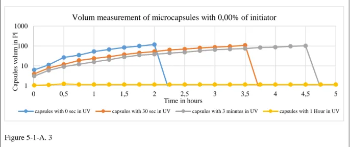
5-1-A.1 Initiator concentration 0.0% ... 135
5-1-A.2 Initiator concentration 0.01% ... 140
5-1-A.3 Initiator concentration 1 % ... 141
5-1-A.4 Initiator concentration 10.0% ... 143
5-2 Size distribution of Capsules ... 145
5-2-A Bright Field Images by Optical Microscopy ... 145
5-2-A.1 Aqueous Phase / Aliphatic Urethane acrylate shell / Aqueous Phase ... 145
8
5-2-B Fluorescence Images Using Dissolved Dyes ... 148
5-2-B.1 Aqueous Phase / Aliphatic Urethane Acrylate Shell / Aqueous Phase System... 148
5-2-B.2 Oil / Epoxy Urethane Acrylate Polymer shell / Aqueous Phase ... 148
5-2-C Sizes Distribution of capsules through Laser Light Scattering ... 150
5-2-C.1 Aqueous Phase / Aliphatic Urethane acrylate shell / Aqueous Phase ... 150
5-2-C.2 Oil / Epoxy Urethane Acrylate polymer Shell / Aqueous Phase ... 151
5-2-D Transmission electron microscopy ... 152
5-2-D.1 Aqueous Phase / Aliphatic Urethane acrylate shell / Aqueous Phase ... 152
5-2-D.2 Oil / Epoxy Urethane acrylate shell / Aqueous Phase ... 153
5-2-D.3 Aqueous Phase / Epoxy Urethane Acrylate Shell / Oil Phase ... 153
5-3 Encapsulation efficiency ... 155
5-3-A Aqueous Phase / Aliphatic Urethane Acrylate polymer shell / Aqueous Phase ... 155
5-3-B Oil phase / Epoxy Urethane acrylate polymer shell / Aqueous phase ... 155
5-4 Methods for triggering the rupture of capsules ... 156
5-4-1 Rupture by osmotic stress ... 156
5-4-2 Rupture by mechanical pressure ... 157
5-4-2. A Capsules contain aqueous core phase, Rubbery polymer shell CN991 aliphatic urethane di acrylate and external phase of water between two glass slides ... 157
5-4-2. B Capsules contain aqueous core phase, Glassy polymer shell CN2035 aliphatic urethane di acrylate and external phase of water between two glass slides ... 158
5-4-3 Rupture by ultrasound ... 159
5-4-4 Rupture by thermal expansion of the core ... 160
9
Chapter 1
10
Aims of the work
The main objective of this thesis is to present a new process for the fabrication of microcapsules, which is based on emulsification of non-miscible fluids, without the use of any surfactant. The only requirements are favorable interfacial energies and a viscosity ratio between the inner phase (phase 1) and the liquid polymer that is used to make the shell (shell, phase 2) that is close to 1, and between this liquid polymer (shell, phase 2) and the outer phase (phase 3) that is also close to 1.
We made two types of microcapsules. We designed capsules with a core made either of an aqueous solution of sodium alginate or of poly alpha olefin 40 oil. The shell is made of a free radical cross linkable aliphatic or epoxy urethane acrylate liquid polymer. These capsules are dispersed in an aqueous solution. We used these capsules for the following goals:
1) To determine the physical properties of the fluids used to prepare the microcapsules: density, viscosity and interfacial tensions.
2) To trace an emulsification diagram for the first emulsion and for the double emulsions according to the viscosity ratios and to the shear rates and to find the optimum fragmentation conditions.
3) To visualize the fragmentation of the double emulsion and to make movies which capture the steps of the fragmentation of the double emulsions for both types of microcapsules.
4) To measure the effects of initiator concentration and UV exposure on the polymerization of the shell polymer.
5) To evaluate the encapsulation efficiency for both types of microcapsules.
6) To compare different methods for triggering the rupture of the capsules and the release of encapsulated material.
11
Organization of the manuscript
This thesis is organized as follows: Chapter 1
Introduction: definition of emulsions and microencapsulation.
Chapter 2
Literature review about emulsions and the microencapsulation process.
Chapter 3
Focuses on emulsion preparation. This chapter starts with a characterization of the physical properties of the fluids that are used to prepare the microcapsules. We determine experimentally the fragmentation diagram for single and the double emulsions by varying the viscosity ratio and the shear rate to find the conditions of optimum fragmentation.
Chapter 4
Next we present visualization experiments: images and movies of double Emulsion fragmentation which show the steps of double emulsions fragmentation for the two types of microcapsules.
Chapter 5
Then we study the effects of initiator concentration and UV exposure duration on the polymerization. We characterize the microcapsules by measuring their size distribution via ImageJ for the images obtained through bright field optical microscopy, Fluorescence images of dyes dissolved in the acrylate shell, and Laser beam scattering using a Master Sizer and also through Transmission electron microscopy for both types of capsules. We determined the encapsulation efficiency for these capsules and we present different methods for triggering the rupture of the capsules and the release of their content.
12
Introduction
1-1-Introduction of Microencapsulation
Microencapsulation is the process of enclosing small solid particles, liquid droplets or gas bubbles with a thin film of coating or shell material. The release of their content can be triggered under specific environmental conditions. In microencapsulation, the material inside the microcapsules is referred to as the core, whereas the coating of this core is sometimes called a shell or wall material. The term microcapsule describes particles with diameters between 1 and 1000 μm. Depending on the morphology of the microcapsules, they can be classified into two basic categories as mono-core type and multiple-nuclear (matrix) type, as shown in Figure 1.1.
Figure 1. 1
Two structures characteristic of commercial microcapsules: (a) mono-core type (b) multi nuclear (matrix) type.
Microencapsulation technologies have been extensively used in the pharmaceutical and food industries. The main motivations are (1) controlled and/or site-specific release of encapsulated drugs (2) protection of the encapsulated materials against oxidation and external environmental conditions like light or moisture), (3) masking of odour, taste and colour of encapsulated materials, (4) Improving the shelf-life of encapsulated materials, (5) protection of encapsulated materials from undesirable phenomena, and (6) ease of use handling as powder-like encapsulated materials.
13
1-2-Emulsion classification
Colloid dispersions are systems that consist of small particles with sizes in the range 1-1000 nm [19]. Simple colloidal dispersions are two-phase systems consisting of a dispersed phase and a continuous phase. Table 1.1 shows the different classifications of simple colloidal dispersions [19]. Emulsions are liquid-liquid dispersions comprised of two non-miscible liquids. They are thermodynamically unstable [19]. In emulsions, one of the two liquids forms the continuous phase in which the other is dispersed as spherical droplets. There are two main types of emulsions that can be made: oil-in-water (o/w) or water-in-oil (w/o).
It is difficult to determine the type of emulsion with the naked eye. However, there are five simple tests that can be used: dilution, dye-solubility, filter paper (CoCl2), fluorescence and conductivity. The
dilution technique is based on the solubility of the continuous phase. O/W emulsions can be diluted with water and w/o emulsions can be diluted with oil. The dye-solubility test uses either a water-soluble or oil-water-soluble dye and then the emulsion is observed with the microscope. If a water-water-soluble dye is used, then an o/w emulsion will have a dyed continuous phase and a w/o will have a dyed dispersed phase. The filter paper tests involve impregnating filter paper with CoCl2. After the paper is
dried it should have a blue tint, and when it is dipped in an o/w emulsion the filter paper will change from blue to pink. The fluorescence test operates on the idea that under UV light some oils are fluorescent. Using this test o/w emulsion show spotty patterns, while w/o emulsions are fluorescent. The conductivity test requires a light bulb attached with wires to two electrodes. When the electrodes are dipped in the emulsion a o/w emulsion will cause the bulb to glow due to the good electrical conductivity of water, while a w/o emulsion will not glow due to the low conductivity of oils [20]. Colloidal dispersions are heterogeneous in nature and always consist of at least two phases: the dispersed phase and the dispersion medium. Dispersed Phase: It is the substance consists of particles or droplets of colloidal size (1 to 100 nm). Dispersion Medium: It is the medium in which the colloids particles are dispersed.
For example, in a colloidal dispersion of sulphur in water, sulphur particles constitute the ‘dispersed phase’ and water is the ‘dispersion medium. Each of the two phases namely, dispersed phase and dispersion medium can be solid, liquid or gas. Thus, different types of colloidal solutions are possible depending upon the physical state of the two phases. Different types of colloidal solutions and their examples are shown in Table 1.1. You should note that gases cannot form a colloidal solution between themselves, because they form homogenous mixtures.
14 Types of Colloidal Solutions
Table 1. 1
Table Types of Colloidal Solutions
Out of the various types of colloids listed above, the most common are sols (solid in liquid type), gels (liquid in solid type) and emulsions (liquid in liquid type). If the dispersion medium is water, then the ‘sol’ is called a hydrosol; and if the dispersion medium is alcohol then the ‘sol’ is called an alcosol.
15
1-3-Formulation
1-3-1-How Emulsions Are Made
To make a metastable emulsion, in addition to oil and water an emulsifier must be present. Due to the immiscibility of oil and water the emulsion is naturally unstable. However, if an emulsifier is added the emulsion can become kinetically stabilized. Emulsifiers improve stability by preventing droplets calescence. Emulsifiers are structured to have a hydrophilic head that is solvated by the water phase and a hydrophobic or lipophilic tail that is solvated by the oil phase.
Figure 1. 2
Structure of o/w and w/o emulsions
Pictured at the top of Figure 1.2. Emulsifiers act as a protective layer between the droplet phase and the continuous phase that prevents the droplet from coalescence with other droplets [19]. In emulsion stabilised by surfactants, the type of emulsion (W/O or O/W) is determined by Bancroft’s rule: the continuous phase is the one in which the emulsifier is preferentially soluble. For instance, with hydrophilic surfactant such as C12E6, the emulsion may be oil in water even when the oil volume
fraction is 95%, conversely it is possible to produce a water in oil emulsion with lipophilic surfactant even when the water volume fraction is 95%. (Aronson and Petko, Lissant) [21].
However, in the present work, we have no surfactant and therefore Bancroft’s rule does not apply. We shall see that the emulsion types are then determined mainly the relative volumes of the aqueous phase and of the oily phase. If the two phases have very different volumes, the phase that has the lowest volume is typically the dispersed phase, while the phase with the larger volume is the continuous phase. However, if the phases are roughly equal in volume, then other factors can influence which phase is the continuous and which phase is the dispersed phase [13].
The usual process for making an emulsion involves a Rayleigh instability to break the drops into smaller droplets and the Marangoni effect to prevent the coalescence of these droplets.
In a first stage, mechanical or hydrodynamic shear forces are applied to the emulsion, this causes the droplets to become elongated. Rayleigh has shown that for a given volume of disperse phase, a cylinder has higher surface area than a sphere, consequently a varicose instability will grow when the droplets are sufficiently elongated and it will fragment the original drop into a large number of droplets.
In emulsion made with surfactants, a Marangoni effect stabilizes the new droplets and prevents their coalescence: the surface pressure of the surfactant creates a surface flow toward the new surfaces and this surface flow produces a bulk flow of continuous phase that keeps the droplets away from each other.
However, in the present work, we did not use any surfactants. The mechanism that stabilizes the new droplets is not known, it can be a combination of surface forces and hydrodynamic forces.
16
Figure 1. 3
Emulsion formation through breakdown in (b) 1 is the continuous phase and 2 is the dispersed phase [9]
The dispersion process is also influenced by the shear in the system, viscosity of the phases, interfacial energy, the pressure of solid particles, and dissolved substances [9]. Droplet breakup can be determined by the critical Weber number. The critical Weber number for turbulent flow is also dependent on the density and viscosity of the dispersed phase, as well as, the droplet diameter and interfacial tension. The Weber dimension is defined by equation 4, where is τdef the deformation
stress, r is the radius of the droplet, and σ
Weber number [9]
is the interfacial tension. When the following two conditions are met droplet break up takes place [Isaa92, pg.53]. Frist, when the Weber number is greater than the critical Weber number. The second condition is that the deformation time must be longer than the critical deformation time. The critical deformation time is shown in equation 5, where Ƞd is the viscosity of the dispersed phase and is ∆P
the Laplace pressure difference [9].
Critical deformation time [9]
Emulsions formulation and droplet size are heavily dependent on the method used, the emulsifier concentration, dispersed phase concentration, energy input, and temperature. The influence of these factors will be discussed in more detail in the following section.
1-3-2- Shearing of Coarse Emulsions
It is possible to generate monodisperse emulsions by applying a shear (tangential) force to viscoelastic emulsions with large, polydisperse droplets [6]. A crude polydisperse emulsion is first prepared by progressively incorporating oil into the continuous phase containing a surfactant. In a second step, a high shear rate is applied to the crude emulsion which becomes monodisperse after no more than a few seconds (Figure 2.3). The shear has the effect to reduce both the average droplet diameter and the distribution width [17].
17
Figure 1. 4
Images of monodisperse emulsion formation by shearing coarse emulsions. (a) The droplets of the precursor emulsion elongate into long cylinders under an applied shear stress, and (b) break up into aligned droplets of similar size. From [17].
The shear stress induces a Rayleigh instability in the droplets by stretching them into long cylinders. Under the driving force of surface tension, the cylinders break up into droplets to minimize their surface area. The final drop size is primarily determined by the rate of growth of the varicose
instability, and is slightly affected by the ratio of the dispersed and continuous phase viscosities. This latter parameter influences the distribution width and appears to be relevant to control the final
monodispersity. If the viscosity ratio p between the dispersed and continuous phases lies between 0.01 and 2, the shear force applied to the coarse polydisperse emulsion leads to a monodisperse emulsion with a mean diameter directly governed by the stress [17].
The viscosity ratio is defined as
It is necessary that the precursor emulsion (either O/W or W/O) is viscoelastic and the shear rate is well controlled. By tuning these variables, it is possible to produce emulsions with mean droplet diameters between 0.3 and 10µm with polydispersity as low as 1.06, although typical values are closer to 1.16 [5].Additional polydispersity may be introduced if the precursor emulsion contains droplets smaller than the mean droplet diameter of the final monodisperse emulsion [7].
1-4- Droplet dynamics
The viscoelastic properties of emulsions are intimately linked to the ability of the suspended droplets to pack and deform [3]. The shape of a droplet is governed by a balance between competing forces: the shear stress applied during a rheological experiment and the interfacial tension [10]. The shear stresses tend to stretch and elongate the droplet in the direction of the flow, while the interfacial tension and viscosity of the droplet oppose the elongation [1].
The influence of these effects is given by the capillary number and viscosity ratio first introduced in chapter 3
18 And
quantified droplet deformation by introducing the deformation parameter
where L and B are the lengths of the major and minor axes of the droplet with volume (4/3) πLB2, respectively. The deformation parameter is zero for a spherical droplet
and tends to 1 as the droplet becomes infinitely slender.
In terms of the capillary number and viscosity ratio, the deformation parameter is:
If p < 1, low shear rates (typically below 1 s-1) cause the droplet to elongate and assume an elliptical
shape with its long axis orientated to the direction of shear as the shear rate increases, the droplet is further elongated and its long axis rotates into the plane of shear. At higher shear rates, the droplet may deform further into long, thin threads until a critical shear rate is reached when the droplet will break.
When p > 1 the degree of deformation is modest. At most the droplet will form a prolate ellipsoid with its long axis orientated in the direction of shear and no breakup is observed [10].
The deformable nature of droplets is responsible for the non-Newtonian and viscoelastic effects seen in the majority of emulsion systems, even when both phases are Newtonian liquids.
19 Summary for the first chapter in french language
Résumé du premier chapitre :
Définition des émulsions et de la microencapsulation et types de colloïdaux solutions.
Pour produire une émulsion métastable, un émulsifiant doit être présent en plus de l'huile et
de l'eau. En raison de l'immiscibilité de l'huile et de l'eau, l'émulsion est naturellement
instable. Cependant, si un émulsifiant est ajouté, l'émulsion peut être stabilisée cinétiquement.
Cependant, dans le présent travail, nous n’avons utilisé aucun émulsifiant. Le mécanisme qui
stabilise les nouvelles gouttelettes n'est pas connu. Il peut s'agir d'une combinaison de forces
superficielles et de forces hydrodynamiques.
Il est possible de générer des émulsions monodisperses en appliquant une force de
cisaillement (tangentielle) aux émulsions viscoélastiques à grosses gouttelettes
polydispersées. La contrainte de cisaillement induit une instabilité de Rayleigh dans les
gouttelettes en les étirant dans de longs cylindres. Sous la force motrice de la tension
superficielle, les cylindres se décomposent en gouttelettes afin de minimiser leur surface.
L'influence de ces effets est donnée par le nombre de capillaires et le rapport de viscosité
introduits au chapitre 3.
20
Chapter 2
21
2-1- Droplet rupture under shear flows
A key stage in the creation of an emulsion is the deformation of larger drops and their subsequent break up in shear flows. The interfacial force holding a droplet together must therefore be overcome in order to deform a droplet and this can occur if a large enough viscous shear force is applied to the drop. Taylor in 1934 did the first pioneering work to understand these mechanisms using an experimental setup consisting of a “four roller mill”
[2]
. The apparatus consisted of four independently controllable rotating cylinders submerged in a continuous phase. A droplet was introduced into the center of the assembly, and by varying the cylinders’ rotation, droplet rupture could be observed under a multitude of different shear flows. The possible flow conditions of the device ranged from elongational flow with no vorticity, to pure shear (Couette flow) consisting of equal parts vorticity and elongation. Taylor’s findings can be crudely summarized as follows, albeit with different terminology:The ratio between the interfacial tension and the counteracting shear forces can be expressed by using the capillary (Ca) number. Small values of Ca represent dominance of interfacial forces over the applied shear and therefore drops are only slightly deformed. Increasing Ca leads to higher deformations and once a critical value is reached the droplet can no longer exist in an equilibrium state and ruptures into two or more droplets. The capillary numbers for pure shear flow and elongational shear flow are calculated as:
Where the variables are: shear rate (γ̇), deformation rate (ε̇), dynamic viscosity of continuous phase (μc), droplet radius (r), and interfacial tension (σ).
Taylor’s predictions for critical capillary numbers, however, were limited as only one viscosity ratio was used in his experiments. In order for a droplet to be ruptured under equilibrium conditions (i.e. neglecting time), it has been found that the critical capillary number is affected by both the type of the shear field and the viscosity ratio (𝑝) of the emulsion.
Where the viscosity ratio (𝑝) is the dispersed phase viscosity (ƞd) divided by the continuous phase viscosity (ƞc).
22
Figure 2. 1
Grace curves - critical capillary number for various viscosity ratios under simple (pure) shear flow and 2-D elongation flow
[4].
In 1982 Grace radically improved the theory of droplet rupture by doing many experiments using the same four roller mill apparatus but this time using many different viscosities for the fluids
[15]
. His results can be seen in Figure 5 and to this day are widely used in emulsifying process design to predict required shear flows for emulsions of desired sizes. It is important to note that droplet rupture is promoted when viscosities of both phases are similar.However, these predictions were valid for emulsions stabilized by surfactant only.
Since the work by Grace, there have been many more studies of drop rupture under similar conditions, with a focus on drop shape, effects of shear cessation during rupture, and how many drops result during and after break-up.
Comprehensive works such as those by Bentley, Stone, Leal, and Rallison [12] - [18] go to great detail in describing the dynamics of droplet rupture and can be briefly generalised as follows:
P < 1. Droplets submitted to capillary numbers just short of the critical value are stretched into stable shapes. The lower the viscosity ratio, the more elongated these steady shapes become. When a critical value is reached they rupture into two or more drops, the more elongated the stable shape, the more drops will result from the rupture. As well as the main drops resulting from the rupture, satellite (much smaller drops) drops are often formed in between the main drops. The lower the viscosity ratio, the higher the likelihood and number of satellite drops are formed.
P > 1. Above a viscosity ratio of 3.5, drop rupture cannot occur in pure shear flows (under such conditions droplets rotate instead of changing shape).
23
2-2- Sub and Super critical capillary rupture
When creating an emulsion, predicting the final droplet size is often the most important factor in the process design. The works described in the section above are crucial in understanding how much shear is required to rupture emulsion drops of known size and properties but are impractical in predicting final droplet size for most emulsifying processes. Critical capillary numbers are calculated theoretically or determined experimentally, by assuming a very slow increase of shear until rupture occurs whereby at all lower shear values the droplet maintains a stable equilibrium shape. This description of gradual shear increase is at odds with the majority of emulsification processes where often drops are subject to a sudden increase in shear far above critical values [4].
Under supercritical capillary number conditions, drops do not have time to form equilibrium shapes and instead are stretched into long thin liquid threads. The less the drop resembles a sphere and the thinner the liquid cylinder becomes, the less force is required to further deform the drop and so the drop keeps stretching
[11]
. Once a drop deforms into a long and slender continually stretching state, capillary waves begin to appear on the surface. At some point the amplitude of this varicose instability becomes too large and the droplet breaks into many (potentially thousands) drops due to Rayleigh-Plateau instability[15]
,[14]
.Understanding and predicting when a stretching liquid thread will rupture into many drops is a very complicated task and not well understood, which makes final droplet size predictions challenging. It is known that viscosity ratio plays a very important part in this process, increasing viscosity ratio results in increasing the stretch before rupture as the higher the viscosity, the more viscous damping occurs on the forming capillary waves. It has been shown that the most efficient viscosity ratio for forming small drops under shear is not equal to one, as the Grace graph suggests, but to use higher viscosity ratios to maximize droplet stretching (and minimize satellite drops) before rupture
[4]
.Another important phenomenon worth discussing is the fact that drops can also be ruptured under sub-critical capillary number conditions. As mentioned above, droplets can be stretched into very long liquid threads at super-critical conditions which continue to stretch until rupture occurs, however, if the shear flow is suddenly stopped during this stretching, instead of returning to its original drop shape, the liquid thread often ruptures into many drops (more prominent at low viscosity ratios). When considering a very low viscosity ratio system, stable equilibrium drop shapes at sub-critical conditions can be extremely slender and long, and it has been shown that if the shear flow is stopped suddenly (rather than gradually), this long slender shape will rupture into many drops
[15]
,[14]
,[18]
. Another phenomenon associated with sub-critical rupture is “tip-streaming”, this only occurs in surfactant containing continuous phases and at low viscosity ratios. The droplet will obtain a stable slender shape, but instead of entirely rupturing, very small droplets will be formed and released from the pointed ends of the slender drop. This is due to the forced movement of surfactant molecules at the surface of the drop from the center to the ends, thus creating a distribution of interfacial tensions along the slender drop with much lower interfacial tensions at the points[14]
.24
2-3- Methods used to create monodisperse emulsions
2-3-1-Controlled shearing of emulsions
It has been shown by Mason and Bibette
[6]
–[17]
that monodisperse emulsions can be created by applying uniform shear stress to a polydisperse coarse emulsion. The reasoning behind this is that if every droplet in an emulsion is subjected to a large enough shear stress that is equal for every droplet, then the droplets will all rupture and reduce in size to a value below the critical capillary number. In order to subject an emulsion to a uniform shear stress a Couette flow is utilized (Figure 2.2). Couette flow is observed when a liquid is placed between two parallel plates where one is stationary and the other is moving. Due to the non-slip condition of the liquid at the plate boundaries, a viscous shear driven flow is induced where the shear stress at every point in the liquid is equal.
Figure 2. 2
Simple Couette flow
This flow regime can be created using various geometries but the most common is two concentric cylinders where on rotates and the other is stationary (Figure 2.3).
25
2-3-2- Couette instrument
Figure 2. 3
Scheme of a commercialized Couette cell where a coarse emulsion is forced through an area of uniform shear stress to create monodisperse emulsions
It was discovered, however, that monodisperse emulsions are only produced if the initial coarse emulsion is shear thinning
[5]
, whereas shearing Newtonian emulsions yields polydisperse results. The proposed reason for this is the mechanism of droplet rupture. When a polydisperse shear-thinning emulsion is sheared, the diameters of all the liquid threads formed from drop stretching at rupture are very similar (therefore resulting in similar sized drops). However, when a polydisperse Newtonian emulsion is sheared, the diameter of the liquid threads produced at rupture seems to be a function of the initial droplet size and therefore yields polydisperse results[7]
,[8]
.This special case of monodisperse rupture that occurs if the emulsion is shear-thinning may at first seem rather specific in application, as the majority of industrial emulsions do not contain shear thinning materials as their continuous phases. However, when an emulsion’s phase ratio is increased to levels above ≈ 50%, the increased droplet interactions due to the close packing dramatically changes the rheology of the emulsions increasing its viscosity and exhibiting shear-thinning effects [16]. It is for this reason that this method of creating monodisperse emulsions has great potential in being used for a very wide range of materials.
26
2-4- Emulsion stability
Once an emulsion is formed there are mechanisms by which an emulsion can be destroyed; one being coalescence, another being Ostwald ripening. Coalescence is the mechanism by which when two droplets come together, the thin film of continuous phase separating the two is ruptured and the droplets merge into one bigger droplet. The rate of coalescence can be reduced by using surfactants to coat the droplets and by reducing the size of the droplets.
Ostwald ripening is the mechanism where dispersed phase in smaller droplets dissolves in the continuous phase and precipitates on to larger droplets causing smaller droplets to shrink and larger droplets to grow
[22]
.Figure 2. 4
27
2-4-1 Coalescence
The coalescence phenomenon of drops in liquid / liquid systems is reviewed with particular focus on its technical relevance and application. Due to the complexity of coalescence, a comprehensive survey of the coalescence process and the numerous influencing factors is given. Subsequently, available experimental techniques with different levels of detail are summarized and compared.
These techniques can be divided in simple settling tests for qualitative coalescence behavior investigations and gravity settler design, single-drop coalescence studies at flat interfaces as well as between droplets, and detailed film drainage analysis.
To model the coalescence rate in liquid/liquid systems on a technical scale, the generic population balance framework is introduced.
Additionally, different coalescence modeling approaches are reviewed with ascending level of detail from empirical correlations to comprehensive film drainage models and detailed computational fluid and particle dynamics [23].
Figure 2. 5
28 Summary for the second chapter in french language
Résumé du deuxième chapitre :
Nous présentons la rupture des gouttelettes sous les écoulements de cisaillement et les
courbes de Grace - nombre de capillaires critiques pour divers rapports de viscosité sous un
écoulement de cisaillement simple (pur) et un écoulement d'élongation 2D.
Nous présentons de méthodes utilisées pour créer des émulsions monodisperses par
cisaillement contrôlé d'émulsions à l'aide de l'instrument Couette.
29
Chapter 3
30
3-1- Physical Properties of the Fluids
3-1-A- Density
We have measured the density of all the fluids in this study. These values are required in the calculation of the interfacial tension, the density different also control the creaming velocity of the droplets and capsules.
1- Density values for the system made of Aqueous core / Aliphatic Urethane
Acrylate Shell / Aqueous External phase
The aqueous phase was either water or an aqueous solution of sodium alginate of concentration 7%, 10% and 15%, the shell was a cross-linkable aliphatic urethane acrylate liquid polymer.
No: Material name Density in g/cm3 at 25°C
1 water 0.994
2 Aqueous solution of 7 % sodium alginate 1.029 3 Aqueous solution of 10 % sodium alginate 1.043 4 Aqueous solution of 15 % sodium alginate 1.051 5 Aliphatic urethane acrylate CN991 liquid polymer 1.239
Table 3-1-A. 1
Density values of fluids used in the aqueous phase / acrylate shell / aqueous phase system
The results show that there are no large density differences. This makes it easier to control the sedimentation or creaming of the droplets and capsules.
2- Density values for the system made of Oil PAO40 core/ Epoxy Urethane Acrylate
Shell / Glycerol external phase
The oil phase is poly alpha olivine40, the shell is Epoxy Urethane Acrylate liquid polymer and the external phase is Glycerol.
No: Material name Density in g/cm3 at 25°C
1 Poly alpha olivine 40 0.841
2 Glycerol 1.2536
3 Epoxy urethane acrylate liquid polymer 1.236 4 Epoxy urethane acrylate polymer with 10% of HDDA 1.1447
Table 3-1-A. 2
31
The results show that there are significant differences between the density values. This suggests that the droplets of poly alpha olefin can cream in the liquid epoxy urethane acrylate polymer and the capsules can cream in glycerol.
According to the sedimentation equation of the droplets of the oil poly alpha olefin with size 15 µm.
Sedimentation velocity of a particle is given by Stokes' law:
V =2( dp − df) 𝑔 𝑟
2
9Ƞf
where V is the sedimentation rate terminal, fall or settling velocity, d is the density (p and f respectively indicate particle and fluid), g is the acceleration due to gravity, r is the radius of the particle and Ƞf is the dynamic viscosity of the fluid.
Aqueous core phase capsules
Creaming of droplets of aqueous solution of 10% sodium alginate in aliphatic urethane acrylate liquid polymer
No: Droplets Size in µm 60 40 20 10 1 Creaming speed in mm/h -1.632793388 -0.72568595 -0.181421488 -0.045355372 2 Comment fast creaming slow creaming slow creaming slow creaming
Table 3-1-A. 3
From the results it is negative values because the droplets have lower density than the outer phase, so it will cream by the time.
Creaming speed of droplets of solution of sodium alginate 10% have size 60µm is -1.632 mm/h and the one that have size of 10µm is -0.0453 mm/h. from that the speed of creaming decreased with decrease the size of the droplets.
Sedimentation capsules of aqueous solution of 10% sodium alginate shell of aliphatic urethane acrylate polymer in external phase aqueous solution of 10% sodium alginate
No: Capsules Size in µm 60 40 20 10 1 Sedimentation speed in mm/h 0.465802129 0.207023169 0.051755792 0.012938948 2 Comment fast creaming fast creaming slow creaming slow creaming
Table 3-1-A. 4
From the results it is positive values because the capsules have higher density than the outer phase the aqueous solution of 10% sodium alginate, so it will sediment by the time.
sedimentation speed of capsules that have aqueous solution of sodium alginate 10% and shell of aliphatic urethane acrylate have size 60µm is 0.4658 mm/h and the one that have size of 10µm is 0.0129mm/h. from that the speed of sedimentation decreased with decrease the size of the capsules.
32 Oil core phase capsules
Creaming of droplets of PAO40 in Epoxy urethane acrylate liquid polymer
No: Droplets Size in µm 20 10 5 3 1 Creaming speed in mm/h -0.281110744 -0.070277686 -0.017569421 -0.006324992 2 Comment Fast creaming Slow creaming Slow creaming Slow creaming
Table 3-1-A. 5
The results it is negative values because the oil droplets of PAO40 have lower density than the outer phase epoxy urethane acrylate polymer, so it will cream by the time.
Creaming speed of oil droplets of PAO40 in epoxy urethane acrylate as external phase have size 20µm is –0.2811 mm/h and the one that have size of 3µm is -0.0063mm/h. from that the speed of creaming decreased with decrease the size of the droplets.
Creaming of droplets of PAO40 in Glycerol
No: Droplets Size in µm 20 10 5 3 1 Creaming speed in mm/h -0.352372985 -0.088093246 -0.022023312 -0.007928392 2 Comment Fast creaming Slow creaming Slow creaming Slow creaming
Table 3-1-A. 6
The results it is negative values because the oil droplets of PAO40 have lower density than the outer phase Glycerol, so it will cream by the time.
Creaming speed of oil droplets of PAO40 in Glycerol as external phase have size 20µm is –0.3523 mm/h and the one that have size of 3µm is -0.0079 mm/h. from that the speed of creaming decreased with decrease the size of the droplets.
Creaming capsules of PAO40 shell of epoxy urethane acrylate polymer in external phase Glycerol
No: Capsules Size in µm 20 10 5 3 1 Creaming speed in mm/h -0.272177913 -0.068044478 -0.01701112 -0.006124003 2 Comment Fast creaming Slow creaming Slow creaming Slow creaming
Table 3-1-A. 7
From the results it is negative values because the capsules have lower density than the outer phase, so it will cream by the time.
Creaming speed of capsules that have PAO40 oil as core and shell of epoxy urethane acrylate in Glycerol as external phase that have size 20µm is –0.2721 mm/h and the one that have size of 3µm is -0.00612 mm/h. from that the speed of creaming decreased with decrease the size of the capsules.
33
3-1-B- Rheology
The aim of measuring the fluids viscosity was to find the concentration that yields the optimum viscosity ratio for the fragmentation of droplets. The other benefit is to find out whether the polymer solution is a dilute Newtonian fluid or a semi-dilute non-Newtonian fluid.
3-1-B.1 Viscosity of Aqueous phase / Aliphatic Urethane Acrylate Shell / Aqueous
phase System as function of shear rate
The aqueous phase was prepared from water with different concentrations of sodium alginate 0%, 7%, 10% and 15%, and the acrylate shell was made of the aliphatic urethane acrylate liquid polymer. The viscosity was measured at shear rates ranging from 1 to 2000 sec -1
No: Description Viscosity pas at 1sec -1 Viscosity pa.s at 10sec -1 Viscosity pa.s at 100sec -1 Viscosity pa.s at 500sec -1 Viscosity pa.s at 1000sec -1 Viscosity pa.s at 2000sec -1 1 Aliphatic urethane acrylate CN991 liquid polymer 10.3602 10.0579 9.76346 -- -- -- 2 water 0.037658 0.00287538 0.00150547 0.00158087 0.00203399 0.00269181 3 Aqueous solution of sodium alginate 5% 0.579143 0.549588 --- --- --- --- 4 Aqueous solution of sodium alginate 7% 2.6850 2.11424 1.30088 0.78988 0.615121 0.094742 5 Aqueous solution of sodium alginate 10% 14.9934 8.28345 3.65076 1.83509 0.352791 0.020604 6 Aqueous solution of sodium alginate 15% 291.513 55.0585 15.1648 0.765473 0.120133 0.029286 Table 3-1-B. 1
Viscosity of the fluids in the aqueous phase / acrylate shell / aqueous phase system plotted as a function of shear rate
The aliphatic urethane acrylate polymer is a Newtonian fluid since it has almost constant viscosity at all shear rates.
On the other hand, the aqueous solution of sodium alginate at concentrations higher than 5% is strongly shear-thinning. This indicates that the polymer solution is semi-dilute, that is the macromolecules are overlapped.
Another important consequence of this non-Newtonian behaver of concentrated sodium alginate solutions is that, they transmit a much smaller stress than Newtonian fluids at the same shear rate. This is important for the emulsification process.
34
Figure 3-1-B. 1
Graph of the viscosity of fluids plotted against shear rate for aqueous phase / acrylate shell / aqueous phase system
From the graph we see that at low shear rate the aliphatic urethane acrylate polymer has almost the same viscosity as the 10% aqueous solution of sodium alginate.
Since the aliphatic urethane acrylate liquid polymer is Newtonian but the solution of sodium alginate is shear-thinning the viscosity ratio will not have the same values at different shear rates. This is an important difference compared to the case where all the fluids are Newtonian.
Figure 3-1-B. 2
The variation of solution viscosity with alginate concentration shows, a concentration of 10% of sodium alginate, the alginate macromolecules are strongly overlapped
0,01 0,1 1 10 100 1000 1 10 100 1000 10000 visco sity p a.s shear rate s ¯¹
viscosity vs shear rate
alginate 7% alginate 10% alginate 15% Liquid acrylate 0,1 1 10 100 1000 30 300 So lu tio n v isco sity P a.s Polymer conentration kg.m־³
viscosity of alginate solution vs alginate concentration
1s¯¹ 10 s¯¹ 100 s¯¹ 500 s¯¹ Exponent 4
35
3-1-B.2 Viscosity of Oil phase / Epoxy Urethane Acrylate Shell / Aqueous
System VS Shear rate
The internal phase oil is poly alpha olivine40, the acrylate shell is Epoxy Urethane Acrylate liquid polymer and the external aqueous phase is Glycerol.
No : Description Viscosity pa. s at 1sec -1 Viscosity pa. s at 10sec -1 Viscosity pa. s at 100sec -1 Viscosity pa. s at 500sec -1 Viscosity pa. s at 1000sec -1 Viscosity pa. s at 2000sec -1 2 75% CN109 with 25% HDDA 0.845093 0.847270 --- --- --- --- 3 100% Glycerol 0.969308 0.918148 0.922537 0.914022 0.862442 0.765855 1 PAO 40 0.922470 0.900229 0.879400 0.875925 0.864336 0.780864 Table 3-1-B. 2
Viscosity of poly alpha olefin oil (core), polymer shell Epoxy urethane acrylate polymer and Glycerol vs shear rate.
Figure 3-1-B. 3
Graph of the viscosity values of fluids plotted vs shear rate for oil / Epoxy urethane acrylate shell / aqueous phase system.
Since all these fluids Glycerol, PAO40 Oil, and Epoxy urethane acrylate polymer have almost constant viscosity values regardless of shear rate, we conclude that are Newtonian fluids.
0,1 1
1 10 100 1000 10000
Shear rates PAO40 Shear rates Epoxy Shear rates Glycerol
36
3-1-C Interfacial Tension
The aim of these experiments was to find out if the effect of wetting can stabilise the topology of the droplets and the capsules, we measured interfacial tensions through the pendant droplet (PD) method. This optical method uses the shape of a drop of a liquid in another non-miscible liquid in a cuvette.
Figure 3-1-C. 1
37
3-1-C.1 Interfacial Tension of Aqueous phase / Aliphatic Urethane
Acrylate Shell / Aqueous phase System
The aqueous phase was prepared from water with different concentration of sodium alginate 0%, 3%, 7% and 10% and the acrylate shell from the Aliphatic Urethane Acrylate liquid polymer.
No: Pendent drop fluid Continues phase Interfacial tension mN/m 1 Aliphatic urethane acrylate CN991 Water with 0% Sodium alginate 13,7 2 Aliphatic urethane acrylate CN991 Water with 3% Sodium alginate 13,1 3 Aliphatic urethane acrylate CN991 Water with 7% Sodium alginate 12,9 4 Aliphatic urethane acrylate CN991 Water with 10% Sodium alginate 13,4
Table 3-1-C. 1
Since fluids 1 and 3 are chemically identical, the relevant interfacial tensions are between fluids 1 and 2 and also between 2 and 3.
Aqueous Phase / Acrylate Shell / Aqueous phase Model
Figure 3-1-C. 2
Capsule structure of aqueous phase / acrylate shell / aqueous phase with the labeling of the three phases
To simplify the equation, we used the following symbols:
Interfacial tension between phase 1 and 2 = A Interfacial tension between phase 2 and 3 = B Interfacial tension between phase 1 and 3 = C
38
In a double emulsion the general equation for stable wetting is C > A + B
But in our case the C = 0 mN/m, there for we do not have the stability provided by wetting. 0 mN/m < 13.4 mN/m + 13.4 mN/m
0 mN/m < 26.8
There is no stability originating from the interfacial tension between the fluids. This would make us believe that the possibility to produce these capsules is low.
39
3-1-C.2 Interfacial Tension of Oil Phase / Acrylate shell / Aqueous Phase
System
The oil phase is poly alpha olivine 40, the acrylate shell is Epoxy Urethane Acrylate liquid polymer and the aqueous phase is Glycerol.
No: Description Interfacial tension mN/m Temperature °C
1 Glycerol in oil 22.41 25.0
2 Epoxy urethane acrylate in oil 5.24 25.0 3 Glycerol in epoxy acrylate 11.81 25.0
Table 3-1-C. 2
Interfacial tension between the fluids of oil / acrylate shell / aqueous phase system
Oil / acrylate shell / Aqueous Phase Model
Figure 3-1-C. 3
Capsule structure with labeling the three phase
To simplify the equation, we used the following symbols:
Interfacial tension between phase 1 and 2 = A Interfacial tension between phase 2 and 3 = B Interfacial tension between phase 1 and 3 = C
In a double emulsion the general equation for stable wetting is C > A + B
40
22,41 mN/m > 5,24 MN/m + 6,57 mN/m 22,41 mN/m > 11,81
There is stability originating from the interfacial tension between the fluids. This would make us believe that the possibility to produce these capsules is very high.
41
3-2 Fragmentation Diagram
3-2-A Shear Rate Applied by the Overhead Mixer
The aim of this section is to evaluate the shear rate where the emulsification take place. The shear rate is highest in the gap between the Anchor stirrer and the internal wall of the beaker, and this is the region where the droplets will be broken by hydrodynamic forces.
We used a R 1330 Anchor stirrer with a diameter Ø: 4.5 cm, Shaft Ø: 8 mm, Shaft length: 350 mm and a VWR213-1171 Borosilicate glass beaker with an internal diameter Ø = 5.0 cm and the volume 150ml. Therefor the gap was 0.25 cm.
Figure 3-2-A. 1
Emulsification equipment: overhead mixer, anchor stirrer and glass beaker
Approximate shear rate in the beaker
The shear rate in the gap is calculated from the ratio of the linear velocity of the blade tip to the gap with:
Shear rate in Sec−1=Linear velosity in m/s Gap in m The linear velocity V is calculated from the angular velocity W:
V = r × W
Where V is the linear velocity in m/s, r is the radius in m, and W is the angular velocity in rad/s V = r × RPM × 0.10472
Hence for rotational speed of 200 rpm:
V = 0.045 × 200 × 0.10472 = 0.9424 m/s Therefore, the shear rate is: 0.9424 m/s
0.0025 m = 376 Sec −1
42
No: Rotational speed in rpm
Radius of
mixer in m Gap in cm Gap in µm Gap in m linear Velocity m/s shear rate sec-1
1 200 0.045 0.25 2500 0.0025 0.94248 376.992 2 500 0.045 0.25 2500 0.0025 2.3562 942.48 3 1000 0.045 0.25 2500 0.0025 4.7124 1884.96 4 2000 0.045 0.25 2500 0.0025 9.4248 3769.92 Table 3-2-A. 1
Approximated shear rate applied by overhead mixer
We will see that the choice of the shear rate is extremely important: firstly, if the shear rate is too low, one may obtain multicore capsules with excessively large polydisperse diameters. secondly if the shear rate is to high it will break the capsules and we may obtain polymer spheres instead of capsules particularly if the interfacial tension is not in the right sequence.
43
3-2-B Fragmentation Diagram for the First Emulsion
3-2-B.1 First Emulsion: Aqueous Phase in Aliphatic Urethane Acrylate
Liquid Polymer
- Materials and Equipment:
Deionized water with zero concentration of salt, Sodium Alginate: this is an ionizable polysaccharide extracted from algae. It has a molar mass in the range 20000 to 42000 g/mol
Aliphatic urethane diacrylate CN991 this is a liquid polymer with difunctional. It can be cross linked by exposure to UV light and particularly to free radicals.
Initiator for UV polymerization (2-hydroxy 2-methylpropiophenone)
Scale, Plastic beaker, Overhead mixer, UV oven, Glass slides and covers slip, Small plastic pipette, Optical microscope.
- Preparation of aqueous solutions and liquid polymers:
1- Aliphatic acrylate shell liquid polymer
Place 19.5g of aliphatic urethane diacrylate polymer CN991 in a 50 ml beaker, add to it 0.5g of hydroxy 2-methylpropiophenone and mix them using the overhead mixer for 2 minutes at 2000rpm.
2- Sodium alginate solution:
Place the appropriate amount of sodium alginate (1% to 15%) in a 100 ml beaker and add to it the appropriate amount of deionized water to avoid losing the powder from the top surface of the beaker then mix them using the overhead mixer for 5 minutes at 1000 rpm and transfer it to a closed small bottle, used it the next day.
- Emulsification
Place 4 g of aliphatic urethane acrylate liquid polymer in a 50ml plastic beaker and add to it 4 g of the aqueous solution of 1% sodium alginate.
Attach it on the overhead mixer and use a rotational velocity 200 rpm for a duration of 1 minute Take a small droplet from the emulsion, using a small plastic pipette and place it on a glass slide, then add a cover slip and put it in the UV oven for 1 minute in order to maintain the same structure during the emulsification then examine it on the optical microscope using the objective lens 100X.
Repeat the experiment with fresh solution of acrylate liquid polymer and water with using angular velocity 500, 1000 and 2000 rpm for duration 1 minute.
Repeat the experiment with using the second aqueous solution of 3%, 5%, 7%, 10% and 15% sodium alginate with starting with the different rotational velocity 200, 500, 1000 and 2000 rpm.
44
Note:
All the images show emulsions after polymerization of the acrylate liquid polymer by UV radiation, because the emulsion is not stable in contact with glass surfaces. Indeed, the acrylate liquid polymer wets the glass slide and the cover slip, causing droplet coalescence and destruction of the emulsions.
Imaging the results of emulsification through optical microscopy
The flowing bright field images show the state of the first emulsion after emulsification of aqueous solution with different concentrations of sodium alginate in aliphatic urethane acrylate liquid polymer CN991. The objective lens was 100x and the scale bar was 20 micrometres.