OATAO is an open access repository that collects the work of Toulouse
researchers and makes it freely available over the web where possible
Any correspondence concerning this service should be sent
to the repository administrator:
[email protected]
To cite this version: Blin, Nassime and Taîx, Michel and Fillatreau, Philippe
and Fourquet, Jean-Yves Tuning Interaction in Motion Planning with Contact.
(2016) In: 2016 25th IEEE International Symposium on Robot and Human
Interactive Communication (RO-MAN), 26 August 2016 - 31 August 2016
(New-York, United States).
Official URL:
https://ieeexplore.ieee.org/document/7745231
This is a Publisher's version published in:
Tuning Interaction in Motion Planning with Contact
Nassime Blin
1, Michel Ta¨ıx
2, Philippe Fillatreau
3and Jean-Yves Fourquet
3Abstract— This work deals with planning processes for the assistance to manipulation in order to simulate industrial tasks such as assembly, maintenance or disassembly in Virtual Reality. This paper presents a novel interactive path planning algorithm with contact based on an BiRRT approach.
First, we propose a real-time interactive planner where both a computer and a human operator simultaneously search the workspace therefore largely speeding up the process. An authority sharing parameter can control the autonomy of the computer.
Then we present a novel contact-space algorithm able to sample on the surface of obstacles. This method helps finding paths in cluttered environments or solving specific contact tasks such as insertion or sliding operations. We finish by presenting the results of our interactive path planner with contact through three examples showing significant improvement over usual methods in both free and contact space.
I. INTRODUCTION
Our goal is to perform path planning for an industrial part to be manipulated (e.g. for an assembly task). This manipulated part will be called object in the rest of this paper. Using widely known motion planning algorithms we can find a solution to such a problem.
Probabilistic planners such as RRT can be very slow to solve problems in difficult spaces such as cluttered or narrow passages. In the context of immersive simulations in Virtual Reality, we can use the help of a human operator to solve the planning problem faster.
Humans often find a path very fast or see that a passage is impossible almost instantaneously. On the opposite, they sometimes fail to see correctly looking a long time for a path in the wrong passage. Without help, navigation in a six dimensional space (position and orientation) is difficult. This is why we believe that combining both the computational power of an automatic planner and the capacity of a human operator can be rewarding for planning the motion of an object.
Traditional path planning algorithms have been developed in order to detect obstacles. Here, we aim at simulating in-dustrial tasks such as assembly, involving sliding or insertion operations [1], [2], [3]. For such operations, motion planning algorithms with contact need to be developed as assembly itself means getting objects to touch each other. We believe
1LAAS-Gepetto, Universit´e de Toulouse, CNRS, Toulouse, France and
Laboratoire G´enie de Production (LGP), Universit´e de Toulouse, INP-ENIT, Tarbes, France
2LAAS-Gepetto, Universit´e. de Toulouse, CNRS, UPS, Toulouse, France 3Laboratoire G´enie de Production (LGP), Universit´e de Toulouse,
INP-ENIT, Tarbes, France
This work was supported by R´egion Midi Pyr´een´ees and Universit´e F´ed´erale de Toulouse Midi Pyr´een´ees
that in these cases, contact planning would require less nodes and time to find a solution path.
This paper is organized as follows : in section I a survey of motion planners related to our work is presented. Section II introduces our novel interactive algorithm for motion planning with contact. Section III presents implementation and results. Last, section IV presents our conclusions and future work.
A. Path Planning
Among all types of motion planners, we will discuss here sampling based algorithms only. These algorithms rely on the fact that they have probabilistic completeness. The two most used methods are the Probabilistic Roadmap Method (PRM) [4] and the Rapidly-exploring Random Tree algorithm (RRT) [5]. They have been extensively studied [6] and an excellent survey is available [7]. There exist real-time algorithms in lower dimension such as [8] but they are not interactive because the tree expansion is not controlled by an operator. We focused our work on RRT because it is a faster solution than PRM, growing faster in constrained environments. B. Interactive Planning
In this section, we present a survey of interactive motion planning algorithms involving both an algorithm and a hu-man operator.
In [9] the authors present a method for cooperation be-tween a human and an automatic motion planner. A haptic device can guide and improve the interaction between them [10]. In other studies, the user interaction can be made using a haptically controlled object to modify or define critical object configurations [11].
Ladev`eze introduced an interactive planner [12]. A linear interpolation between the current configuration and the goal configuration generates an attraction force guiding a user through a haptic device.
Flavign´e [13] introduced the Interactive RRT (IRRT). Its goal is to move an object in free space. This solution lets an operator control the sampling process using a haptic arm.
More recently, Cailhol [14] implemented an original multi-layered interactive solution. In two steps, he finds a topologic path in the environment and then finds a precise path using geometric information to control an object. Both of these phases are controlled according to semantic information.
All these algorithms are interactive but they lack one feature that is contact planning.
C. Contact Planning
Classically, the goal of motion planning is to move an object in the free space Cf ree of a workspace while trying
to avoid obstacles. Oppositely, our goal is to plan motion at the surface of obstacles.
Redon [15] published a solution to locally plan on contact. When an in-contact configuration is found, the next generated node is projected on a set of valid variations satisfying all global non collision constraints. The main drawback of this method is that it is not global. Its goal is not to plan in contact but rather to get out of it.
Rodriguez [16] uses obstacle based information to gener-ate configurations parallel to obstacles. This helps expanding PRM graphs in cluttered environments in a much better way than a standard PRM. Though this solution plans parallel to obstacles, it still cannot plan in contact.
Yan [17] proposed a very efficient contact planning solu-tion using a retracsolu-tion technique. An operator with a device first draws a path allowed to have colliding parts. This path is then locally retracted to the surface in a post treatment to generate contact paths.
D. Contribution
To the best of our knowledge, there exist no interactive algorithm capable of searching the whole workspace and able to plan directly on surfaces. We coupled interactivity with contact planning which none of the methods of part I-B implemented. Therefore we have implemented an I-BiRRT interactive in contact algorithm. We chose BiRRT because this algorithm is capable of expanding quickly in narrow passages and is known to be much more efficient than a standalone RRT.
Our contribution is twofold: an in-contact solution without any post treatment coupled with an interactive algorithm greatly speeding up motion planning processes.
Based on the principle of the previous interactive al-gorithms part I-B, we implemented our own interactive solution.
It possesses to distinct loops: the computer loop and the human loop. While the computer loop is a standard BiRRT, trying to extend the tree at each iteration, the human loop consists of an interactive device allowing to move an object in the workspace with six degrees of freedom.
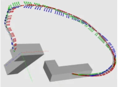
An operator is then capable of manually defining qdevice,
the geometric center of the object’s root body, see figure 1.
Fig. 1: Moving object and roadmap visualization Our algorithm then chooses at each iteration who is getting authority: computer or operator. A random number between 0 and 1 a is shot at each iteration. If this value is greater than
α, a predefined interactivity parameter, then the authority will be given to the computer and a random sample will be shot. On the opposite, we will choose the configuration given by the operator.
Please see [18] for more details about our interactive algorithm.
II. CONTACT PLANNING
We will present in this section our novel in contact motion planner capable of sampling at the surface of obstacles. The overall behavior is first explained. Then we introduce our interactive motion planner with contact which is our main contribution. We finish by giving an example of contact sampling.
A. Nearest Obstacle
We have models of both the environment and the object geometry. A user moves the object in the workspace using our interactive algorithm [18]. Whenever he approaches an obstacle sufficiently, the planner switches in contact mode at the surface of this obstacle. Moving the object away from the obstacle ends contact mode.
Using a collision detection library, we can measure the obstacle-object distance for every obstacle. The closest ob-stacle is then defined as the contact obob-stacle.
B. Stay in Contact
When starting contact mode, the planner samples on a local tangent plane to the nearest obstacle.
For each of these samples, the actual orientation of the object is chosen by the operator and kept constant during contact allowing only translations. New configurations are randomly chosen along the tangent plane. The object is then able to slide on the obstacles to enhance sampling in specific environments. This is one possible way of sampling at the surface of obstacles and it is called ContactSampling() in the algorithm described below. See [18] for more details about our contact sampler algorithm.
When the object switches to contact mode, a predefined number of contact samples N are added to the tree. We chose this behavior because we want to sample a lot of contact configurations to search more interesting space. Also, as the space may be cluttered, the probability to sample a node in collision is high leading to more rejected in-collision nodes. We are then tempted to sample a high amount of nodes on the surface letting the user quickly slide on surfaces.
The algorithm quits contact mode after sampling the predefined number of nodes; then the position of the operator is checked. If he hasn’t moved or if he stayed close to an obstacle, the algorithm enters back to contact mode. C. Interactive Real-Time Motion Planning with Contact
The real interest of our work and our main contribution is when both interactive and contact sampling is used simul-taneously. We can benefit both from an automated planner searching the whole space and from the operator seeking to guide or slide the object. This algorithm is real-time because
it reacts at operator speed. This means that whenever the operator moves, the algorithms reads a new value. If he does not move, the last input (the current configuration qcurrent)
is chosen. Of course, if there is no solution, the fact that the algorithm is interactive will not help getting this information more than any other sampling based algorithm.
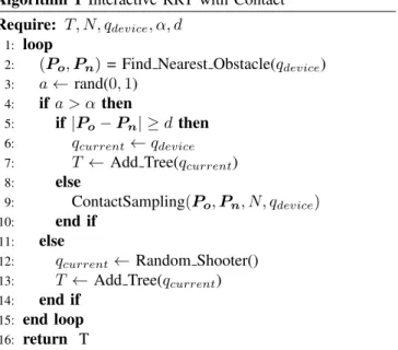
Algorithm 1 Interactive RRT with Contact Require: T, N, qdevice, α, d
1: loop
2: (Po, Pn) = Find Nearest Obstacle(qdevice) 3: a ← rand(0, 1)
4: if a > α then
5: if |Po− Pn| ≥ d then 6: qcurrent← qdevice 7: T ← Add Tree(qcurrent) 8: else
9: ContactSampling(Po, Pn, N, qdevice) 10: end if
11: else
12: qcurrent← Random Shooter() 13: T ← Add Tree(qcurrent) 14: end if
15: end loop
16: return T
For each sample, a random number a defines who holds authority. If a ≤ α, authority is given to the computer and a random configuration is shot. If a > α, authority is given to the operator. In this case, a distance test defines if contact mode should be enabled. Let d be a fixed threshold, if the distance between the object and the obstacle is higher than d, the new configuration is the one given by the interactive device ; if the distance is lower or equal to d it means that the operator is close enough to an obstacle therefore N contact samples are generated on its surface.
Line 2, the function Find Nearest Obstacle() returns the pair of nearest points : Po the nearest obstacle point to Pn
the nearest object point.
Line 3, a random number between 0 and 1 is shot to give authority to an operator (line 4) or a computer (line 11).
Line 5, the distance test defines if contact sampling should be enabled by checking the Po to Pn distance.
The planner switches to contact mode, line 9 by calling ContactSampling() function.
D. Example
Figure 2 gives an example of our interactive motion planner planning on a surface. We have a white L shaped object that has to slide on a plane. Both nodes and edges are displayed.
For this example only, the α parameter describing the au-thority sharing between the random shooter and the operator shooter is set to 1. This means that the only samples kept in the roadmap will be non colliding user defined configurations and contact configurations when in contact mode. This helps observing the behavior of our ContactSampling() function
Fig. 2: Contact example
on its own without the help of the BiRRT. When entering contact mode, the number N of configurations to be shot before switching back to non-contact mode is fixed to 10 for the rest of the paper.
Our test describes two steps of motion planning with different orientations. Starting in position (1), we move the object to the contact and stay a while in this position to sample a lot of aligned nodes (2). In step (3), the user gets out of the contact, rotates the object (4) and gets back to contact. A new set of configurations with a new orientation are generated (5).
We have implemented a novel motion planner capable of generating configurations at the surface of obstacles with the help of an operator. Our choice was to let the operator define the orientation because this can be important in some industrial cases such as insertion but there may be other strategies. We illustrate in the following section the usefulness of our contact algorithm with two examples.
III. IMPLEMENTATION AND RESULTS The following section describes the performances of our algorithms and the influence of the input parameters: contact samples N , authority sharing α, distance to contact d and enabling or not contact mode. All examples are displayed showing only edges of roadmaps for clarity purposes.
This section is organized as follows: part A gives impor-tant implementation details. Part B shows the usefulness of our interactive planner with an illustrating example. Part C presents a cluttered environment in which the influence of the parameters are tested in parts D, E, F, G. Last, in part H, we test our interactive contact algorithm in an even more cluttered environment where a standalone RRT planner fails to find a solution.
A. Implementation details
All experiments are developped and performed using Hpp [19] software developed primarily by the Gepetto team at LAAS-CNRS, the collision detection library used is Fcl [20], the geometric models are all described using URDF (Unified Robot Description Format). The interactive device is a 6D mouse from Immersion company, model 3DConnexion R
Intel XeonR CPU E3-1240 v3 @ 3.40GHz processor withR
16 GB RAM and runs under Ubuntu 14.04.
A particular attention was given to implement our interac-tive algorithm on two different threads. The goal is to let the standard motion planning process alone on its thread and therefore on its processor. All treatments regarding the operator are treated separately on a different thread. As no parallelization of motion planning is implemented we can easily compare our solution with a standard, single processor motion planning implementation.
Treatments regarding the operator are done in the operator thread. They are: reading the 6D mouse data and integrating positions to move the object, cycling through obstacles to find the closest and preparing for contact.
Treatments regarding the computer thread are: BiRRT and ContactSampling(). The overhead slowing this thread is dur-ing contact sampldur-ing mode because each new configuration is transformed to stick the obstacle.
Visualization of the scene is a separate process. B. Cluttered Environment
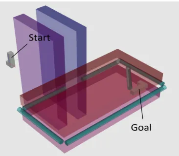
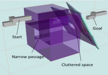
Figure 3 presents environment 1. It is cluttered and hard to solve using simple RRT method. This environment will be used to analyze the influence of the different parameters. It consists of two blue planes forming a cluttered space where the object can rotate only around two on three axis. Two red planes form an even more cluttered space where the object can freely rotate around only one axis on three. Only very small rotations around the two other axis are allowed before getting in collision.
In this experiment, the object is a non-convex L-shape. All passages to get inside the red area are blocked with turquoise bars except in a narrow passage shown figures 4 and 5. The distance between the two first walls is 1.2 meter while the distance between the two next walls is 0.75 meter. The length of the object is 1.6 meter, its height 0.8 meter and its width 0.4 meter. This means that the object can pass through the narrow passage allowing only very small variations around roll and pitch axis. Inside the two red planes, rotation around yaw axis are possible freely.
The goal configuration is located at a corner of the red area behind an oblique bar therefore the object will have to slide in order to reach the goal.
C. Interactivity parameter
We attempt to solve a planning problem in environment 1 with various values of α but without any contact using our interactive algorithm. This means our samples are shot in free space.
The first experiment shown figure 6 involved a simple RRT. It took 2h45 minutes to the algorithm before finding a solution. Were added 27 600 nodes and 55 198 edges to the roadmap. In industrial cases, this time length is not realistic and unacceptable.
All others experiments are held with the help of an experienced user 6D mouse with our interactive algorithm. Figure 7 shows an example with the cooperation factor α set
Fig. 3: Environment 1 : Cluttered Environment
Fig. 4: Narrow passage, side Fig. 5: Narrow passage, up
Fig. 6: Simple RRT Fig. 7: Interactive
to 0.5. Results are shown in table I. As expected, the help of an operator radically changed the speed of the process. Rapidly, when samples lay in an interesting space, random samples also tend to be generated in this space, we can see that the amount of sampled nodes is very small in comparison to the RRT method.
Compared to a standard RRT, our interactive planner outperforms it radically. But authority sharing has a strong influence having a maximal time efficiency with α = 0.95, giving 95% of the time to the computer. The reason is that it is very hard for a user to move correctly in this constrained 6D space. Therefore he needs a lot of help from the computer. Higher values of α do not give enough time to
Fig. 8: Contact α = 0.8 Fig. 9: Contact α = 0.2 Fig. 10: Contact α = 0.05
Scenario α Time Nodes Edges RRT 1 2h45m 27 600 55 198 Interactive 0.99 83s 2 454 4 906 Interactive 0.98 63s 2 059 4 116 Interactive 0.95 25s 891 1 780 Interactive 0.9 30s 1 284 1 074 Interactive 0.6 36s 1 386 2 770 Interactive 0.4 40s 1 372 2 742 Interactive 0.3 108s 2 135 4 268 Interactive 0.2 146s 2 476 4 950 Interactive 0.1 154s 1 878 3 754
TABLE I: Influence of α without contact
the operator to benefit properly from his commands therefore slowing the process.
D. Contact mode parameter
Using our interactive contact method, we are able to improve the efficiency planning processes. Whenever the operator approaches the object to an obstacle, samples are generated along a plane tangent to it and. The tree can grow fast on surfaces. To get inside the red area near the goal configuration, the object should slide along one plane but this requires freezing some degrees of freedom. While this can be a challenge for a random shooter, our in-contact shooter solves the problem much quicker when we want to stay in contact with the obstacle.
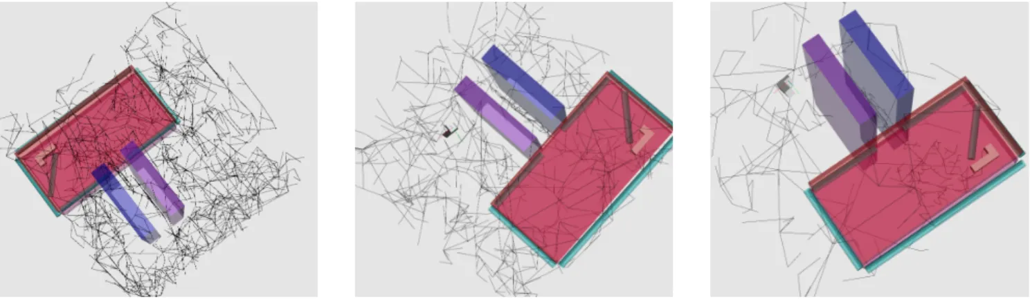
The performance of the contact algorithm is tested with a series of experiments each with a different α value. Figures 8, 9 and 10 show three results with different values of α. Table II shows the results of these experiments.
With a control sharing factor α getting smaller, the time needed to solve the problem reduces until a minimal point is reached with α = 0.08 meaning that the operator has authority during 92% of the processing time. During this time though, all configurations added to the tree are not completely operator defined. because when the user moves the object close to contact, the contact mode automatically expands nodes on the surface. We have three operating modes:
α Time Nodes Edges 1 2h45m 27 600 55 198 0.8 40s 1 729 3 454 0.5 31s 1 314 2 626 0.2 21s 715 1 428 0.1 22s 679 1 356 0.08 14s 538 1 074 0.05 24s 547 1 092 0.04 21s 602 1 202 0.02 31s 658 1 314 0.01 25s 768 1 534 0 47s 894 1 786
TABLE II: Influence of α with contact
• computer exploring randomly
• operator exploring far from obstacles
• operator enabling contact sampling
The parameter α must be very small because otherwise too many nodes and edges are added by the computer in useless space. Values of α smaller than 0.08 loose the benefit from random sampling and the obtained results get less competitive. Either way, our in contact algorithm is always faster than a standard BiRRT, requiring less nodes and edges than the interactive planner without any contact sampling. E. Contact samples parameter
Each time entering contact mode, a number N of samples are generated at the surface chosen by the operator. A series of experiments are held whose results are shown table III. The α parameter is set to 0.2. The results show very little influence of N in the overall process.
F. Distance parameter
Enabling contact requires the operator to approach the ob-ject close to an obstacle. In all our experiments, the threshold parameter d was set to d = 0.15 meter. The influence of this parameter was tested in the same environment with α = 0.2 and N = 5, results in table IV. No influence was observed showing that the value of d is of little or no importance in this environment.
Contact samples N Time (s) Nodes Edges 1 62 1 371 2 740 2 37 1 064 2 126 5 18 711 1 420 10 27 902 1 802 50 36 1 019 2 036 100 42 1 155 2 308 200 43 1 004 2 006 500 52 1 196 2 390
TABLE III: Influence of contact samples N
Distance d (m) Time (s) Nodes Edges 0.02 38 1 075 2 148 0.05 53 1 170 2 338 0.1 36 1 114 2 226 0.2 42 1 130 2 258 0.5 29 1 051 2 100 0.8 34 1 078 2 154 1 35 1 117 2 232
TABLE IV: Influence of distance d
G. When standalone RRT fails
A new extremely constrained space is environment 2, see figure 11. It was tested with our algorithms. We also changed the shape of the object making the problem more difficult. The environment consists in a long tube inside which the object can barely move except for crossing this very narrow passage. It is followed by two thin planes with a small opening. The first plane is rotated around one axis, the second rotated around two axis. This makes a very cluttered place and a big challenge for an operator as the object needs to be rotated correctly and very accurately.
Fig. 11: Environment 2: Very cluttered Environment
The problem was first tested with a standard BiRRT experiment (α = 1). The result after one night of simulation is shown in figure 12. Still no solution being found, we decided to stop the experiment. We also tested α = 0 but it
Fig. 12: Environment 2, α = 1
Fig. 13: Environment 2, α = 0.5
is impossible to cross the cluttered space without the help of a computer.
Our interactive algorithm was then tested without contact. This means no contact samples were generated but there is an authority sharing between the computer and the operator. An experience was held with α = 0.5. A result was finally found by an experimented user after 29 minutes and 22 seconds, adding 9025 nodes and 18 048 edges. This is because it is very complicated to enter inside the narrow passage without help and also very difficult to cross the cluttered space without using the tangent planes as a hint for tree expansion.
α Time (s) Nodes Edges 0.98 197 3 508 7 014 0.95 218 3 741 7 480 0.9 65 2 021 4 040 0.8 68 2 026 4 051 0.7 61 1 818 3 634 0.6 65 1 718 3 434 0.5 138 2 396 4 790 0.4 112 2 051 4 100 0.3 158 2 072 4 142 0.2 132 1 810 3 618 0.1 157 1 423 2 844 0.05 624 2 585 5 168
TABLE V: Environment 2, influence of α,
Last, we tried to solve this experiment with both inter-activity and contact using algorithm 1. Table V shows the results. It is very clear that extreme values of α considerably increase the number of nodes and the speed of our method.
The computer needs the human telling him to sample inside the very constrained tube whose probability to sample inside tends to zero. On the other hand, the operator imperiously needs to be able to cross the rotated planes in a decent length of time. Optimal values are inside the [0.6 - 0.9] range and figure 13 shows the result for α = 0.5. We can see that only a single path was found for the object to cross the very narrow passage.
IV. CONCLUSION & FUTURE WORK
Our interactive contact algorithm makes a step forward in assembly path planning. It is a twofold contribution in-troducing an interactive algorithm sharing authority between a computer and a human operator and a contact sampling method capable of sampling at the surface of obstacle. Our method helps solving cluttered situations where objects need to slide on each other by keeping contact. Some cluttered environments or insertion cases could benefit from this novel algorithm. We have shown the influence of authority sharing on the results of path planning. It was then improved by positioning its parameters to optimal values.
An important point is that it is very difficult to measure interactivity because a human is in the loop as in every method involving a human. Results are strongly dependent on his training level or his concentration. What we can show, however, is that no matter the environment, interactive planning is always better and even more efficient when adding contact sampling for our scenarios.
Generally speaking we can conclude of these experiments that the number of contact samples N should not be too high and that the α parameter is to be chosen depending of the degree of human knowledge needed to solve the problem. A value around 0.5 is best suited when both an operator and a computer are much needed.
The main drawbacks of our method is first that contact sampling cannot follow multiple contact but stays only on one plane at a time and second that the parameters need to be hard coded.
Future work would be to let the algorithm change the parameters automatically depending of the situation and the operator’s moves. This would require setting α and N with a heuristic based on the operator’s actions. The distance parameter that enables switching to contact mode is manually set for now. This parameter indirectly defines how often contact samples are shot. Though it is manually set, we can think of a solution where the operator can change this parameter online as he is the one having the industrial knowledge of the assembly to be done.
We also envisage improving our contact algorithm by implementing a solution capable of following iteratively many different planes and enabling automatic change of orientation. This would let us have more efficient contact sampling.
We would also like to integrate the user in a Virtual Reality platform with a haptic arm to get force feedback to simplify the work of an operator in complex 3D environments. Such
a platform exist in the LGP lab and we are currently working on this improvement.
The algorithm should be tested with a user study. But it needs improvements especially replacing the 6D mouse by a haptic arm. At this moment we will test the algorithm with inexperienced users.
Last, all our work is RRT based because diffusion of a BiRRT in cluttered environments is very efficient and our problems are cluttered. But our goal is to have a library of different planners available in our Virtual Reality platform.
REFERENCES
[1] R. Iacob, D. Popescu, and P. Mitrouchev, “Assembly/disassembly anal-ysis and modeling techniques: A review,” Strojniˇski vestnik-Journal of Mechanical Engineering, vol. 58, no. 11, pp. 653–664, 2012. [2] M. Bordegoni, U. Cugini, P. Belluco, and M. Aliverti, “Evaluation
of a haptic-based interaction system for virtual manual assembly,” in Virtual and Mixed Reality. Springer, 2009, pp. 303–312.
[3] L. Tching, G. Dumont, and J. Perret, “Interactive simulation of cad models assemblies using virtual constraint guidance,” International Journal on Interactive Design and Manufacturing (IJIDeM), pp. 95– 102, 2010.
[4] L. E. Kavraki, P. ˇSvestka, J.-C. Latombe, and M. H. Overmars, “Proba-bilistic roadmaps for path planning in high-dimensional configuration spaces,” Robotics and Automation, IEEE Transactions on, vol. 12, no. 4, pp. 566–580, 1996.
[5] J. J. Kuffner and S. M. LaValle, “Rrt-connect: An efficient approach to single-query path planning,” in Robotics and Automation, Proceedings. ICRA’00. IEEE, 2000.
[6] S. M. LaValle, Planning algorithms. Cambridge Univ. press, 2006. [7] D. Hsu, J.-C. Latombe, and H. Kurniawati, “On the probabilistic
foundations of probabilistic roadmap planning,” The International Journal of Robotics Research, vol. 25, no. 7, pp. 627–643, 2006. [8] K. Naderi, J. Rajam¨aki, and P. H¨am¨al¨ainen, “Rt-rrt: a real-time path
planning algorithm based on rrt,” in Proceedings of the 8th ACM SIGGRAPH Conf. on Motion in Games. ACM, 2015, pp. 113–118. [9] O. B. Bayazit, G. Song, and N. M. Amato, “Enhancing randomized motion planners: Exploring with haptic hints,” Autonomous Robots, vol. 10, no. 2, pp. 163–174, 2001.
[10] J. Rosell, C. V´azquez, A. P´erez, and P. I˜niguez, “Motion planning for haptic guidance,” Journal of Intelligent and Robotic Systems, vol. 53, no. 3, pp. 223–245, 2008.
[11] X. He and Y. Chen, “Haptic-aided robot path planning based on vir-tual tele-operation,” Robotics and computer-integrated manufacturing, vol. 25, no. 4, pp. 792–803, 2009.
[12] N. Ladeveze, J. Y. Fourquet, B. Puel, and M. Taix, “Haptic assembly and disassembly task assistance using interactive path planning,” in Virtual Reality Conf. IEEE, 2009, pp. 19–25.
[13] D. Flavign´e, M. Ta¨ıx, and E. Ferr´e, “Interactive motion planning for assembly tasks,” in The 18th IEEE International Symposium on Robot and Human Interactive Communication. RO-MAN 2009. IEEE, 2009. [14] S. Cailhol, P. Fillatreau, J.-Y. Fourquet, and Y. Zhao, “A hierarchic approach for path planning in virtual reality,” International Journal on Interactive Design and Manufacturing (IJIDeM), vol. 9, no. 4, pp. 291–302, 2015.
[15] S. Redon and M. C. Lin, “Practical local planning in the contact space,” in Robotics and Automation, 2005. ICRA 2005. Proc. of the 2005 IEEE Int. Conf. on. IEEE, 2005, pp. 4200–4205.
[16] S. Rodriguez, X. Tang, J.-M. Lien, and N. M. Amato, “An obstacle-based rapidly-exploring random tree,” in Proceedings 2006 IEEE International Conference on Robotics and Automation. IEEE, 2006. [17] Y. Yan, E. Poirson, and F. Bennis, “Integrating user to minimize as-sembly path planning time in plm,” in Product Lifecycle Management for Society. Springer, 2013, pp. 471–480.
[18] N. Blin, M. Ta¨ıx, P. Fillatreau, and J.-Y. Fourquet, “Interactive Motion Planning with Contact,” Mar. 2016. [Online]. Available: https://hal.archives-ouvertes.fr/hal-01297010
[19] F. Lamiraux and J. Mirabel, “Hpp: a new software framework for manipulation planning,” 2015.
[20] J. Pan, S. Chitta, and D. Manocha, “Fcl: A general purpose library for collision and proximity queries,” in 2012 IEEE International Conference on Robotics and Automation (ICRA), 2012.