O
pen
A
rchive
T
OULOUSE
A
rchive
O
uverte (
OATAO
)
OATAO is an open access repository that collects the work of Toulouse researchers and
makes it freely available over the web where possible.
This is an author-deposited version published in :
http://oatao.univ-toulouse.fr/
Eprints ID : 18409
To link to this article : DOI:
10.1016/j.electacta.2017.08.023
URL :
http://dx.doi.org/10.1016/j.electacta.2017.08.023
To cite this version :
Iranzo, Audrey and Chauvet, Fabien and
Tzedakis, Théodore Synthesis of submicrometric dendritic iron
particles in an Electrochemical and Vibrating Hele-Shaw cell: study
of the growth of ramified branches. (2017) Electrochimica Acta, vol.
250. pp. 348-358. ISSN 0013-4686
Any correspondence concerning this service should be sent to the repository
administrator:
[email protected]
Synthesis
of
submicrometric
dendritic
iron
particles
in
an
Electrochemical
and
Vibrating
Hele-Shaw
cell:
study
of
the
growth
of
ramified
branches
A.
Iranzo,
F.
Chauvet
*
,
T.
Tzedakis
*
LaboratoiredeGénieChimique,UniversitédeToulouse,CNRS-INPT-UPS,Toulouse,France
Keywords: ironelectrodeposition sonoelectrochemistry ramifiedgrowth nucleation microstreaming ABSTRACT
Thepurposeofthisstudyistoexploreanewsynthesiswayfortheproductionofironnanoparticles exploitingthenanometricstructureoflongramifiedironbranchesformedbyelectrodepositionina Hele-Shawcell.Afterthegrowth,thesebranchesarefragmentedbytheactionofavibratingelement (piezoelectricdisk)integratedintothecell.Theemphasisisputonthegrowthoftheramifiediron brancheswhichisperformedbygalvanostaticelectrodepositioninastagnantelectrolyte(FeCl2)inside
the Hele-Shaw cell (50mm deep). The competition betweenthe co-formation of H2 bubbles (H+
reduction)andthegrowthoframifiedironbranches(FeII reduction)isanalyzedbyvaryingboththe applied current density j and the FeCl2 concentration. Two regimes, depending mainly on j, are
highlighted:belowathresholdcurrentdensityof8mA/cm2onlyH
2bubblesareformed,whileabovethis
threshold,ironbranchesgrowaccompaniedbytheformationofH2 bubbleswhichnucleateandgrowat
thetopofthebranchesduringtheirformation.TheH2 bubblesinfluencethebranchesgrowthespecially
atlowj(<24mA/cm2)whenthegrowthvelocityofthebranchesislowcomparedtothegrowthrateof
thebubbles.Athigherj(>24mA/cm2),thebranchesfollowacolumnargrowthwithaconstantfront
velocity,wellpredictedbythetheory.ScanningElectronMicroscopy(SEM)oftheironbranchesshowsa dendriticstructureconstituted ofnanometric crystallites,whosesizedependsonthelocal growth velocity:increasingthegrowthvelocityfrom3.6mm/sto40mm/sleadstoadecreaseinthecrystallites size,from!1mmto!10nm.Usingtheacousticvibrations(4kHz)ofthepiezoelectricdisk,thesefragile branches are successfully fragmentedinto submicrometricfragments of dendrites exhibiting high specificsurfacesS/V(equivalenttotheS/Vofnanoparticlesof30nmdiameter).Advantages/Drawbacks comparedtoothersynthesiswaysaswellastheoptimizationoftheproposedsynthesisarediscussed.
1.Introduction
Metallicironnanoparticlesattractsignificantinterestbothfor theirmagneticandcatalyticpropertiesinvariousfields(medical, energy,andenvironment).Inthemedicalfield,evenifironoxide nanoparticleshavebeeninvestigatedfortheirmagnetic proper-ties,forMagneticResonanceImaging(MRI)[1]orcancertreatment
[2], they appear to be less efficient when compared to iron nanoparticleswhichexhibitenhancedmagneticproperties[3].In addition, ironnanoparticlesare increasinglyinvestigated inthe treatment of contaminated watersand soils [4–6]due totheir reductiveproperties. Indeed,due tothe lowstandard electrode
potential of the Fe2+/Fe0 system (E"=#0.44V/SHE), their high
specific surface and their porous iron oxide/hydroxide outside layer,theseironnanoparticlesshowahighreactivityandallowthe removal of pollutants [5] such as ions of heavy metals or chlorinatedorganiccompounds[7].
Conceptually,nanoparticles canbe synthesizedthrough two globalapproaches,top-downandbottom-up.Thefirstoneconsists of using a large-sized material (micrometric particles for examples) which is chemically or physically cut off until the nanometricsizeisreached.Thebottom-upapproachconsistsof the reverse process; small building blocks (like atoms) are assembled to form nanoparticles. Based on these two global approaches, various physical or chemical syntheses have been exploredtoproduceironnanoparticles(ball-milling[8],thermal reduction of iron salt [9,10], iron salt wet-chemical reduction
[11,12]).
* Correspondingauthor
E-mailaddresses:[email protected](F. Chauvet),
Among the wet-chemical syntheses, theproduction of iron nanoparticlesbyreductionofanironsaltbyaborohydridesalt (colloidal synthesis) is a method commonly employed at the laboratory scale [7]. Nevertheless, this synthesis requires specificconditions,firstbecauseoftheriskofgaseoushydrogen production(causedbyborohydrideoxidation)andsecondlydue tothe toxicity, corrosiveness,andflammability of the borohy-dride reductant [9,13]. Additionally, a step of purification is required to separate the produced nanoparticles from the remaining reacting species and byproducts (dialysis, ion exchange resin, centrifugal or filtration processes). This is required for several reasons: enhancement of the colloidal stability, to avoid the presence of salt crystals during dry characterization of the particles and to avoid contamination/ pollution effects by residues of the synthesis in the final application.
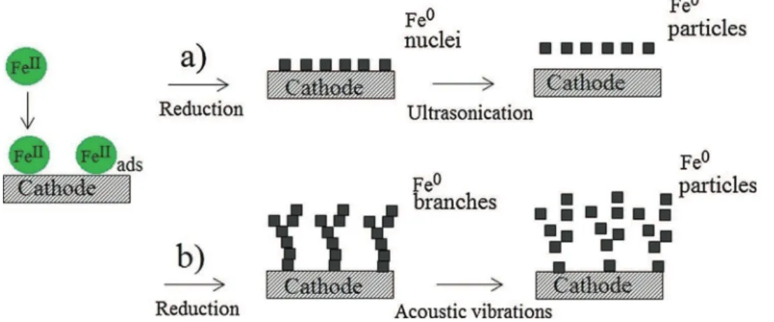
Another technique to produce metallic nanoparticles, here called“sonoelectrochemical synthesis”, combines electrochem-icaland ultrasonicationprocesses. Itconsists inthe electrode-position of iron nanoparticles (nuclei) on a cathode surface whichis subjectedtopowerultrasound(20kHz).The propaga-tionof theultrasonic wavesinducescavitation bubbleswhich, during their violent collapses, create strong enough fluid motion to detach the iron nanoparticles from the electrode surface (Fig. 1a)). Both processes, electrodeposition and ultra-sound,canbeappliedeithersimultaneously[14]orsequentially
[15]. This technique appears to be a promising alternative, avoiding the use of a reductive chemical agent, but: i) the purification step is, here again, required (removal of the supporting electrolyte and remaining metallic precursor) and ii)theultrasoundprocesssuffersfromalowenergeticyield(a large part of the mechanical energy is consumed by the cavitation and streaming generated far from the electrode surface,and so useless for the depositdispersion).
Onthebasisofthislasttechnique,weproposetoexploreinthe presentpaperanewsynthesisrouteaimingtobecosteffective, safeandimplyingalimitednumberofsteps.Asinthecaseofthe sonoelectrochemicalsynthesis, it consistsin producing electro-chemicallythemetallicironparticlesbut,insteadoflimitingthe irongrowthtoobtainnucleilyingontheelectrodesurface,the electrodepositionisdrivenforlongertimesgivingriseto“long” ramified ironbrancheswhich are thenfragmented viaacoustic vibrations,Fig.1b).
Tothatend,an“ElectrochemicalandVibratingHele-Shawcell” hasbeendesigned.ItconsistsofaHele-Shawcell(athingapcell,
50
mm
deep)integratingalow-frequencyacousticdevice (piezo-electric disk, PZT, resonance frequency=4kHz) to induce the vibrations(Fig.2).Theuseofsuchaconfinedgeometryallowsthecontrolofthe iron growth and the generation of ramified deposits. When a currentisappliedtothecell,themetalliccationsMz+arereduced
intometalM0inducingthedecreaseoftheMz+concentrationat
thecathodeinterface(nofluidcirculationintothecell).Whenthe interfacialMz+concentrationreacheszero,themetalhastogrow
undertheformofaporousdeposit(ramifiedbranches)througha successionof nucleation/growthevents (orthewaterreduction takesplace)forthecurrenttokeepflowingthroughthecell[16]. Dependingontheoperatingparameters(applied currentorcell voltage and precursor concentration), the resulting ramified depositsexhibitoneofthethreemainmorphologies(arrangement of the branches): fractal, columnar and dendritic [17,18]. The branchesareknowntobeconstitutedofsmallcrystalliteswhich couldbenanometric(asshownin thecaseof theformationof ramifiedcopper branches[19]).Thus,theidea,proposedinthis work,istoexploitthesmallgranularstructureofthebranches,for the case of an iron deposit, to produce a suspension of iron nanoparticlesviathefragmentationofbranchesinducedbythe PZTvibrations.Thesizeofthecrystallitesthatconstitutetheiron branchesbeingdependentontheappliedcurrentdensity[19],this synthesis route offers an external control of the produced nanoparticles,atleastintermofsize,viatheoperatingparameters (appliedcurrentandironprecursorconcentration).Additionally,in
Fig.1.Schematicrepresentationof:a)theclassicalsonoelectrosynthesiswhichistheremovalbyultrasoundofironnanoparticleselectrodepositedonanelectrodesubstrate, b)thenewsynthesisproposedinthisstudywhichconsistsofthefragmentationunderacousticvibrationsoframifiedironelectrodeposits.
Fig.2. SchematicrepresentationoftheElectrochemicalandvibratingHele-Shaw cellusedinthisstudy.
contrastwiththesonoelectrochemicalsynthesis,theintegrationof thePZTtotheHele-Shawcellallowslocalizingandconcentrating themechanicalactiononthemetalliccrystallitesassemblies.Last but notthe least,in this microfluidic-like device, thebranches couldberinsedbeforetheirfragmentation,whichshouldavoidthe finalpurificationstep.
Asindicatedinapreviouswork[20]andalsoin[21],onaniron electrode,thereductionofFeII(FeCl
2,(NH4)2Fe(SO4)2andFeSO4for
pH<!4)intoFe0isaccompaniedbythereductionoffreeprotons
H+.Therefore,hydrogenbubblesformationisexpectedduringthe
electrodepositionexperimentsintheHele-Shawcell(asshownin S. Bodea et al. [22]). This issue is specifically studied in the following.
The integration of the low-frequency acousticdevice in the Hele-Shaw cell is inspired by its use in microfluidic chips to enhancemixing[23–25].Intheseworks,ithasbeenestablished that the presence of bubbles, trapped into specially designed microchannels,isneeded toallowanefficientmixing[23].The vibrationof thePZTinduces theoscillationof thebubblesthat generatesmicrostreaming(astationaryandasymmetricfluidflow aroundthebubbles[26]).Weproposeheretotakeadvantageofthe microstreaminggeneratedbytheco-producedH2bubblesforthe
fragmentationofthebranches.
ThisstudyfocusesontheeffectofboththeFeCl2concentration
andtheappliedcurrentdensityoni)thegrowthoframifiediron branchesin theHele-Shawcelland ii) theinfluenceof the
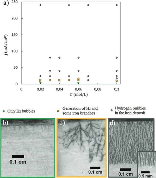
co-Fig.3.Syntheticresultsofvariouselectrolysescarriedoutatvariouscurrentdensitiesandforvariousconcentrationsoftheironprecursor(FeCl2)withoutsupporting
electrolyte.ForeachFeCl2concentration,differentcurrentdensitiesareapplied,andthephenomenaoccurringintheHele-Shawcellareshownina);greencircles:onlyH2
bubbles,yellowsquares:mainlyH2bubbleswithsomeironbranches,greydiamonds:H2bubblesandironbrancheswhichfillthespaceuniformly.Foreachcase,animageofa
typicaldeposit,obtainedunderthecorrespondingconditions,isshowninb)0.02M,4mA/cm2,c)0.06M,12mA/cm2andd)0.1M,80mA/cm2.(Forinterpretationofthe
producedH2bubbles.SEMandTransmissionElectronMicroscopy
(TEM) are used to observe respectively the structure of the branchesaswellastheparticlesresultingfromtheironbranches fragmentation(thefragmentationmechanismwillbedetailedin anotherpaper).Thepurityoftheobtainedaqueoussuspensionof ironparticles,intermofelectrolytesaltcontent(i.e.massfraction ofthemetalliciron),isdeterminedandtheresultiscomparedto theoneobtainedwiththecolloidalandthesonoelectrochemical syntheses.
2.Experimental 2.1.Chemicals
Iron(II)saltsolutionsarepreparedusingnormapursolidFeCl2
(Sigma-Aldrich)inultrapurewater(18.2MV.cm);nosupporting electrolyteisused.The naturalpHoftheFeCl2 solutionsvaries
from3.9to3.3dependingontheFeCl2concentrationsused(from
0.02to0.1Mrespectively).ThepresenceofdissolvedO2mustbe
avoidedtopreventitsco-reductionduringtheelectrodeposition and to limit the Fe0 corrosion. All the solutions are deaerated
(Argon,1bar),during15min(!30mL)beforebeingcollectedbya gastight syringe(Hamilton 1mL,1001LT) and injected intothe Hele-Shawcell.
2.2.Experimentalset-upandmethods
The Hele-Shaw cell is constituted of two iron plates (the electrodes)of a thickness of50
mm
(purity$99.5%),which are 9mmapartand sandwichedbetweenaglassplateandthePZT (ABT-441-RC,Radiospare).Thelengthoftheelectroactivezoneis 2.5cm,Fig.2.Thefaceoftheglassplateexposedtothechannelisentirely coveredbytransparentlaboratoryparafilmsheetactingasagasket toavoidleakageswhilethesurfaceof thePZTis coveredbyan adhesive tape ensuring its protection against corrosion. The contoursoftheHele-Shawcellareclosedbyapplyinganadhesive paste.Twoclamps,pressingontheglassplates,areusedtoholdthe assembly.Thecellisfilledwiththeferrousionsolutionusingthe gastightsyringeviatwomicrotubes(PTFE)connectedtothecellby fluidicconnectionsmadebydrillingholesintheglassplateandby gluing Nanoport connectors (Idex-hs) on them. Special care is takentoavoidtheintroductionofatmosphericoxygeninsidethe channel. The cell is maintained horizontally to avoid natural convectionwhichcouldinfluencethebranchesgrowthandsotheir structure[27,28].Thecellcaneasilybedismantledtobecleaned,or torecovertheirondepositsforSEMobservations.Theelectrodes aremanuallypolishedusingapapergrid(P1200)tooperatewitha reproduciblestateofthesurfaceoftheelectrodes.Theelectrolyses areperformedwithapotentiostat(AutolabPGSTAT100N). Experi-mentsarecarriedoutatroomtemperature(18<T("C)<22).
A typical experiment consists in filling the cell with the electrolyte, then a constant current is applied between the electrodesandthegrowthoftheironbranches,onthecathode, isvisualizedbyacamera.Theoxidationoftheironmadeanode preventstheproductionofbothO2(bubblesneverobserved)and
FeIII.Aftertheirformation,themetallicbranchesarerinsedbya
flow of deaerated ultrapure water using a syringe pump. A sufficientlylowflowrate,!100
mL/min,
isappliedtoavoidboth damagingthe iron branches and the removal of the hydrogen bubbles.Besides,nochangeinthebubblessizeisobserved,dueto boththelowsolubility(!0.8mM)ofH2inwaterandalsoduetothelowsurfaceareaoftheliquidgasinterfacesofthecrushedbubbles in this confined geometry (the smallest apparent diameter of bubblesbeingequalto100
mm).
ThePZTisthenactivatedduring !15s to fragment the branches. The fragmented particles arecollected by pushing them throughthe cell applyinga flow of deaeratedultrapurewater.
2.3.Observationsoftheobtainedironelectrodeposits
2.3.1.Opticalobservationofthegrowthoftheramifiedironbranches The growth of the ramified iron branches is observed by reflectionusingafiberopticilluminatorandacameraPCOpixelfly connectedwitha105mmmacrolens(fieldofview%5mm&5 mm).Apictureofthedepositistakenevery5secondstomonitor theevolutionofitsgrowth.
2.3.2.SEMobservationoftheramifiedironbranchesandpreparation ofthesamples
Toobservethestructureoftheobtaineddeposit,SEMpictures of the ramified iron branchesare taken. The iron depositsare fragile,andtherecoveryoftheramifiedstructurerequiresspecial caution.Aftertherinsingphase,thecellisopenedwhichinduces strong modifications of the branches pattern, but without damaging the microstructure. The deposit is recovered on an adhesivecarbontapeanddriedunderatmosphericconditions.The structureoftheironbranches(beforefragmentation)isobserved bySEMwithaJEOLJSM7100FTTLSoraJEOLJSM7800F Prime-EDS.
2.3.3.TEMobservationoftheparticlessuspensionandpreparationof thesamples
Adropofthesuspension,containingthefragmentedparticles, islefttodryonaTEMgridbeforeanalysiswithJEOLJSM 2100F-EDS.
3.Resultsanddiscussion
3.1.Growthoframifiedironbranchesaccompaniedwiththeformation ofH2bubblesintheHele-Shawcell
Todeterminetheconditionsallowingthegrowthof theiron branches, in the Hele-Shaw cell used, several galvanostatic electrolyses are performed using a stagnant FeCl2 solution, by
varyingtheconcentrationc,from0.02Mto0.1M(thenaturalpH varyingfrom3.9to3.3)andtheappliedcurrentdensityfrom4to 240mA/cm2 (relative to the initial geometrical surface of the
electrode). The obtained results can be classified into three different groups (see Fig. 3), depending mainlyon thecurrent densityjandremarkablyindependentlyoftheconcentration(in theexaminedrange):
– j<!8mA/cm2:H
2bubblesareproduced,andnoironbranches
areobserved(greencirclesinFig.3a)andFig.3b)) – !8<j (mA/cm2)
<!16: large H2 bubbles are produced, and
some partially broken ramified iron branches are observed (yellowsquaresinFig.3a)andFig.3c))
– j>!16mA/cm2:smallH
2bubblesnucleateandgrowatthetop
oftheironbranches,andtheyarecontinuouslyleftbehindthe movingfront(graydiamondsinFig.3a)andFig.3d)).
These results, in agreement with those of Heresanu [29], highlight that thereis a thresholdcurrent density (%8mA/cm2
here,mainlydevotedtotheH+reduction)toovercomeinorderto produceironbranches.
Foranappliedcurrentdensityj<8mA/cm2,theinitialpotential
isnotsufficientlycathodictostartthereductionofFeII.Duetothe
decreaseintheinterfacialconcentrationofH+,thepotentialofthe
cathodedecreasesuntilitreachesthepotentialenablingtoinduce thereductionoftheFeIIions.Anadditionaltimeisthenrequiredto
thetimenecessarytofullydepletetheFeIIatthecathodesurface [30].Theexperimentalresultssuggestthatthislastconditionis neverobtainedforj<8mA/cm2.
Foranappliedcurrentdensityj>8mA/cm2,theinitialpotential
issufficientlycathodictoinducethesimultaneousreductionofFeII
and H+.Duetoboththehighvalueof thecurrentand thelow
concentrationofH+(comparedtoFeIIconcentration),thefraction
ofthecurrentusedfortheH+reductionislowcomparedtotheone
usedfortheFeIIreduction.Thisshortensthedepletiontimeforthe
FeIIandmakesthegrowthofironbranchespossible,asobservedin
the experiments when appliedcurrent densities >8mA/cm2. A
modelbasedonthecouplingbetweenthetransientsemi-infinite diffusionprofilesofH+andFeIIwithButler-Volmerequationswill
beprovidedinanotherpaper.
However,thetransitionbetweenthesetwolimitingcasesisnot easy to model since thegrowth of H2 bubbles at thecathode
surfacecanchangetheelectrolysisconditionslocally:
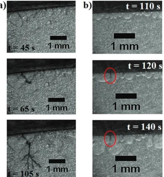
– H2 bubbles cover the electroactive surface of the cathode
implyingtheincreaseofthecurrentdensityimposedtothefree surface,andthen,couldfavorthestartofabranchgrowth. – H2bubblescanalsototallyisolatesomeoftheironbranches
fromthesolutionandconsequentlyblocktheirgrowth.
BothcasesarerespectivelyhighlightedinFig.4a)andb). Even if H2 bubbles are produced whatever the operating
conditions,thedepositgrowthappearstobelessaffectedbytheir presence at high current density (for j>16mA/cm2). This is
because,fortheseconditions,thegrowthvelocityofthebranches ishigherthanthebubblesgrowthrate,leadingtotheformationof smaller bubbles, less disruptive than those produced at lower currentdensity.
3.2.MorphologiesoftheironelectrodepositsintheHele-Shawcell Themorphologiesoftheobtainedironelectrodeposits,atthe macroscopicscale(arrangementofthebranches),arereportedin
Fig.5asafunctionoftheappliedcurrentdensityandtheprecursor concentration.TheobjectivehereistoexaminetheeffectoftheH2
bubbles,electro-generatedsimultaneouslywiththeiron deposi-tion,onthemorphologytransitionsandtocomparewiththemain depositspatterns,andtheassociatedtransitions,usuallyobserved inabsenceofbubbles(fractal-columnar-dendritic)[17,18].
TwomainmorphologiesaredistinguishedinFig.5:thefractal andthecolumnar;nodendriticmorphologiesareobservedatthis macroscopicscale(fieldofview%5mm&5mm).
EvenifitisnotvisibleinFig.5(especiallyatthehighercurrent densities),theformationofbubbles,duringthegrowthoftheiron
Fig.4.OpticalimagestakenduringgalvanostaticelectrolysesintheHele-Shawcellfora)0.02MFeCl2,j=12mA/cm2andb)0.1MFeCl2,j=16mA/cm2.Withthesevaluesof
appliedcurrentdensity,theH2bubblesprogressivelyblocktheelectrodesurface,thatcouldfavorthestartofthegrowthofabrancha)butalsoitsstopb)(seethebranchin
branches,hasbeenconfirmedbymagnifiedvisualizationsforall thedeposits.
Thecolumnarmorphology,whichconsistsofalargenumberof branchesregularlyspaced and growing atthesame velocity, is obtainedmainlyforthecurrentdensitieshigherthan24mA/cm2,
whatever the precursor concentration. Increasing the current density causes the distance between the branches todecrease whichleadstoapparentlydenserdeposits.
Lower current densities, typically a value of 12mA/cm2,
produce deposits with fractal-like morphology, which exhibit openstructureswithfewerbranches,andtheirarrangementisalso lessregularthantheoneobtainedforcolumnardeposits.
Suchatransition,fromthefractaltothecolumnar morphol-ogieswhenthepolarizationmagnitudeisincreased,hasoftenbeen reported for the electrochemical growth of ramified metals withoutH2 bubblesco-formation(zinc [18,31]copper [30–33]),
however the mechanism of this transition is not yet fully understood.
One convincing explanation is the relatively low electrical conductivityoftheporousbrancheswhichregulatestheheightsof thebranchesandthus stabilizesthegrowthfront, especiallyat highappliedcurrentdensities [34].Notethat electroconvective phenomena havealso beenproposed toexplain this transition
[33].
Thedendriticmorphologycorresponds toanorderedcrystal growth(offewmaintrunkswithsecondarybranchestiltedwitha well-definedangle);itisobtainedwhenthegrowth ofmetallic crystalsisfavoredcomparativelytonucleationevents,generallyat thehighestappliedcurrents(thedepositmorphologygoesfrom fractaltocolumnarandthentodendriticwhentheappliedcurrent
increases) [18]. In the present study (Fig. 5) no dendrites are observed at the macroscopic scale, the columnar morphology predominates even at high applied currents. However, as it is shown in the next section (Fig. 7), themorphology is actually dendriticata smallerlengthscale.Itmeansthatthereis stilla competition between nucleation and growth events when the appliedcurrentishigh;thedendritesgrowthisregularlyandearly stoppedbynucleationevents.Thiscouldbeduetotheco-produced H2 bubbles around the iron branches which act as “insulating
shields”thatlimitthelateralgrowthofsecondarybranchesofthe dendritesandensureaconstantseparationdistancebetweenthe branches.
To sum up, the co-formation of H2 bubbles doesnot affect
significantly the transition between the main patterns usually observedforothersystemsinabsenceofH2bubbles.Thebubbles
can only be suspected of affecting the transition between the columnarandthedendritic morphologiesbyalateral shielding effectwhichlimitsthedendritesgrowthathighappliedcurrents. 3.3.Faradaicyieldoftheironelectrodeposition
Asindicatedinthesection3.1,thedepositgrowthappearstobe lessaffectedbytheco-productionofH2bubblesathighcurrent
density, and so for columnar deposits (section 3.2). For this particular case, the faradaic yield of theiron electrodeposition processisestimatedfromthemeasurementofthegrowthfront velocityandthetheorydevelopedin[16].
When metallic branches grow without the formation of H2
bubbles(caseofcopperorzinc),duringgalvanostaticelectrolyses, thecorrespondingcolumnardepositsareboundedbyaflatfront
Fig.5.OpticalimagesofthedifferentdepositmorphologiesobtainedusingtheHele-Shawcellforthegalvanostaticelectrolyses:8'j'240mA/cm2and0.02'FeCl
whichadvancesataconstantandpredictablevelocityvg[16].The
concentration profile of theelectroactive species, ahead of the growthfront,isthenstationaryanditisadvectedwiththefront. Withoutsupportingelectrolyte,themasstransferproblemcanbe reducedtoagenericdiffusion-advectionproblem([35])thathas been used in [16] to obtain the following modeling of the concentrationprofilecðx;tÞaheadofthefront:
cðx;tÞ c1 ¼1#exp xfðtÞ#x Ld ! " ; ð8Þ
withc1thebulkconcentration,x
fðtÞ thegrowthfrontlocation,x
thecoordinateperpendiculartothefrontanddirectedtowardsthe growth direction and Ld¼D=vg the diffusion length, D¼ zþuþDþ
#z#u#D#
zþuþ#z#u# being the diffusion coefficientof theunsupported
electrolyte (where z+, z#and u+, u# are the valences and the
mobilities of thecationicand anionic speciesof theelectrolyte respectively)[35].
Combining Equation (8) withtheboundary conditionatthe frontforthecurrentdensity(assumingthatthemetal electrode-position is quantitative) zþjF¼1#tDþ @c @xjxf (where @c @xjxf¼c 1 Ld, tþ¼ zþuþ
zþuþ#z#u# is thetransference numberand Fis theFaraday’s
constant) [35], the growth velocity of the columnar deposits (withoutH2bubblesformation)isgivenby[16]:
vg¼
jð1# tþÞ
zþFc1 ð9Þ
In Fig.6,forseveral columnarirondepositsproducedinthe presentstudy,themeasuredgrowthfrontvelocityvexpisplottedas
afunctionoftheratio2Fcj1,assumingafaradaicyieldof100%(jis
thecurrentapplied).Aspredicted,vexpdependslinearlyon2Fcj1and
the proportionality factor is equal to 0.56. Thus the t+ value
determinedviathisexperimentalapproach,assumingafaradaic yieldof100%,is0.44.Bycomparingthisexperimentalt+valueto
thetheoreticalone(tþ¼ zþuþ
zþuþ#z#u#Þ,theactualfaradaicyieldofthe
ironelectrodepositioncanbeestimated.
Accordingto[36],forchlorideionsconcentrationlowerthan 1mol/kg, Fe2+ ions are not complexed with the chloride ions.
Thereforehere,itisassumedthatFeCl2isfullydissociatedintoFe2+
andCl#withouttheformationofcomplexes.TheH+concentration
beingalwayswelllowerthanFe2+orCl#concentrations,themain
cations and anions to consider for the determination of the theoreticalt+valuearetheFe2+andtheCl#ions.Atheoreticalt+
valueof0.41isdetermined(assuminganinfinitedilutionofthe species, u.=D./RT, R=8.314J/(mol/K),T=293K, D+=7.19
&10#10
m2/s[37]andD#=2.03&10#9m2/s[38])whichisslightlylower
thanthet+valuedeterminedwiththeexperimentaldata(Fig.6):
0.44.Thisdifferencebetweenexperimentaldataandtheorycanbe interpretedasaconsequenceoftheH+co-reduction.Indeed,the
wholecurrentdensityisnotusedtotheironelectrodepositionand thus,intheexperimentscarriedout,thedepositfrontadvancesa littlemoreslowlythanexpectedbythetheory,assumingafaradaic yield of 100%. Therefore, the actual faradaic yield for the electrodepositionofthecolumnardepositsisestimatedat95%.
These results show that, during the electrodeposition of columnardeposits,analmostnegligiblepart(5%)oftheapplied currentdensityjisallottedtotheH+reduction.Nevertheless,even
iflittleH2gasisgenerated,thebubblesarewellvisiblesincethey
arehighlycrushedintheverythinHele-Shawcellused. 3.4.Small-scalestructureoftheramifiedironbranches
Withtheobjectiveofusingthemicrostructureoftheramified deposits,toproduceasuspensionofironnanoparticles,thesmall scalestructureoftheironbranches,obtainedintheHele-Shawcell, isobservedbySEM.
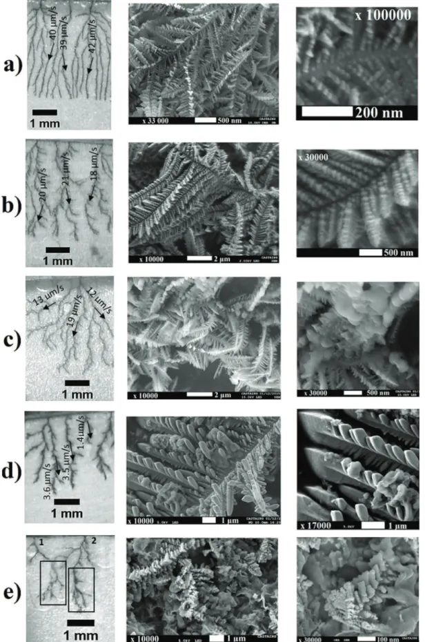
Among the various deposits obtained in this study, five deposits,showingmorphologiesgoingfromcolumnartofractal (8'j'24mA/cm2),havebeenobservedbySEMandthepictures
arepresentedinFig.7:thedepositsshowninFig.7a),b)andc)are obtainedusinga0.02MFeCl2solutionatcurrentdensitiesof24,12
and8mA/cm2respectively;thedepositsshowninFig.7d)ande)
areobtainedusinga0.1MFeCl2solutionatcurrentdensitiesof12
and8mA/cm2 respectively.Tocompare thelargeandthesmall
scalestructuressimultaneously,threedifferentmagnificationsare providedinFig.7.
Forthedepositsobtainedwithaconcentrationof0.02Mandat currentdensitiesrangingfrom24to8mA/cm2(Fig.7a),b)andc)) thesmallscalestructure(picturesinthemiddle)reveals dendritic-likebranches(maintrunkswithsecondarybrancheshighlighting preferred growth orientation) which consist, however, at the nanometricscale(zoomontheright),ofsmallcrystallites.Thesize ofthesecrystallitesvariesfromonedeposittoanother.Thedeposit showninFig.7a)(24mA/cm2,0.02M)appearstoconsistofseveral
rowsofregularcrystallites,withasizeofabout20nm,whilefor thedepositshowninFig.7b)(12mA/cm2,0.02M),thecrystallites
sizeliesintherangeof50–100nm.
Fleurycorrelatesthisfinegranularstructuretotheoscillatory characterofthenucleationkineticsandclaimsthatthecrystallites size is dictated by the growth velocity, and so by the current density(fortheramifiedgrowthofcopper[19]):thehigherthe growthvelocity,thesmallerthecrystallitesare.
Regardingcomparativelytheapparentgrowthvelocityandthe crystallites size v24mA=cm2
; 0:02M
ð Þ % 40
mm/s
!10 ' dcrystallitesðnmÞ' 30; v 12mA=cm2;0:02M
ð Þ % 20
mm/s
!50 ' dcrystallitesðnmÞ '100)itcanbeconcludedthattheseobservations,for theiron case, are consistentwith theaffirmation of Fleury ([19]).
In addition, our results highlight that the influence of the growthvelocityonthecrystallitessizehasadirectimpactonthe regularityof thedeposit structure.Thefractal deposit obtained with8mA/cm2(0.02M),Fig.7c), showsa smallscale structure
(pictureinthemiddle)lessregularthanthedepositsobtainedwith highercurrentdensities,24and12mA/cm2(0.02M),Fig.7a)and
b).Thisdepositexhibits,atthenanometricscale(pictureonthe right)bigcrystallites ofvarioussizesrangingbetween200and
Fig.6.Averagegrowthvelocityofcolumnardepositsasafunctionoftheratio j
2Fc1.
Squares: experimental data; line: best linear fit, vexp¼0:56& 2Fcj1
# $
þ4:3&10#6; concentrations range from 0.02 to 0.1M
Fig.7.SEMpicturesofironelectrodepositsobtainedintheHele-Shawcellatvariouscurrentdensitiesandusingvariousprecursorconcentrations.a),b),c)0.02MFeCl2using
24,12and8mA/cm2respectively;d),e):0.1MFeCl
2using12and8mA/cm2respectively.Millimetric(leftcolumn),micrometric(middlecolumn)andnanometric(right
500nm.Thisbroadrangeofcrystallitessize,inthesamedeposit,is explained by the fractal morphology. Indeed, contrary to the columnardeposit,forafractaldeposit,thegrowthvelocityisnot thesameforallthebranches,thegrowthofsomebranchescan slow down and stop in favor of the growth of others. The estimationofthegrowthvelocityofsomebranchesleadstovalues varying from 12
mm/s
to 19mm/s
(Fig. 7c) on the left) which explainsthedispersionofcrystallitessizesobserved.The deposits shown in Fig.7d) and e) are obtainedusinga higher concentration of0.1M,at two current densities,12 and 8mA/cm2respectively.Atthelargescale(picturesontheleft),the
depositobtainedat12mA/cm2(Fig.7d)),showsthickerbranches thantheotherdeposits.Atthesmallscale,thestructureisordered and thesizeofthecrystallites,composingthebranches,ranges between 500nmand 1
mm
(picturesin themiddle and onthe right).Thisisconsistentwiththelowgrowthvelocityestimatedfor mostofthebranchesofthisdeposit%3.6mm/s;
thislastvalueis aboutfourtimesslowerthanthevelocityvaluemeasuredinthe previouscases.Finally,thedepositobtainedat8mA/cm2(Fig.7e))shows,atthe
largescale,fractalmorphology,butitcanbenoticedthatlargeH2
bubbleshavebeenformedduringitsgrowth.RegardingtheSEM pictures(Pictureinthemiddle),itcanbeobservedthatthedeposit shows areallycomplexsmall-scale structure.Awide varietyof structures isobserved(thin branches,roughstructures,smooth iron blocks...), probably because the generation of H2 bubbles
disturbesstronglythedepositgrowth.Forexample,thegrowthof thebranchlabeled“1”inFig.7e),hasbeenstoppedbythepresence ofanH2bubble.Consideringthebranchlabeled“2”inFig.7e),the
observationsmadeduringtheelectrolysis,showthatthegrowthof therightbranchisstoppedforthebenefitoftheleftbranch.Then, the leftbranchgrowthis stoppedbythepresenceof a bubble, whichreactivatesthegrowthoftherightbranch.Thus,thegrowth ofonebranchisachievedinseveralstepswithdifferentgrowth velocities.
Tosumup,theSEMobservationshaveconfirmedtheFleury’s work[19]fortheironcase:theironbranchesconsistofcrystallites whose size decreases withincreasing theirgrowth velocity. In
addition,the regularity of thecrystallites size, observed atthe nanometricscale,isrelatedtothelarge-scalemorphologyofthe deposits. Fractal deposits consist of polydispersed crystallites whilecolumnardepositsshowcrystallitesofalmostuniformsize. ThedepositshomogeneityisevenmoreaffectedwhenH2bubbles
hinderthedepositgrowth.
Inconclusion,intheprospectofthefragmentationoftheiron branches to produce regular iron nanoparticles, the operating conditionsallowingthegrowth ofcolumnardepositsshouldbe favored.
3.5.Characterizationoftheproducedparticlesafterfragmentation Aftertheformationofacolumnardeposit(80mA/cm2,0.1Mof
FeCl2)anditsrinsing,thePZTisactivated(squareelectricalsignal:
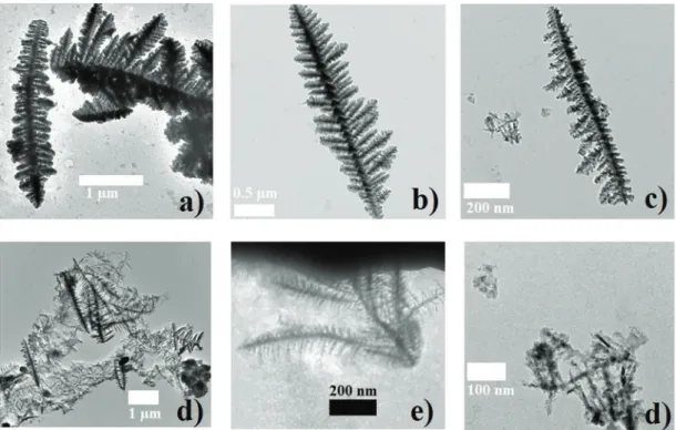
peak topeak voltage=250V, frequency=4kHz, duration=15s). The characterization by TEM of the collected particles (Fig. 8) revealsthattheyareinfactfragmenteddendritesofvarioussizes, from few micrometers (Fig. 8a), b) and c)) to hundreds of nanometers(Fig.8e)andf)).Thesefragmentsofdendrites,shown inFig.8a),b)andc),wereprobablyinitiallysecondarybranchesof maintrunkswhichhavebeencutoffattheirroot.InFig.8a)andb), the micrometric fragments seem to be unaffected by the fragmentationprocess,while in Fig.8c)the fragment seemsto havebeenpeeledoffonitsrightside.Thissuggeststhatsmaller fragments(!200nm)arebrokenbythemechanicalstressinduced bybubblesoscillations.Apileofdendritesalongwithagroupof smallerentitiescanbeseeninFig.8d).Theyconsistofneedle-like fragmentswhichappeartobethesmallbranchesofthesecondary branches.
It can be concluded, that coupling the electrochemical formation of ramified iron branches with their fragmentation, usingtheelaborated “ElectrochemicalandVibrating Hele-Shaw cell”,enablestoobtainasuspensionofdendriticparticlesofsizes varying from hundreds of nanometers to few micrometers. However,themain interestof usingnanoparticlesis theirhigh specific surface, and even if the obtainedfragments are about 1
mm,
theirdendriticshapegivesthemahighsurfacetovolumeFig.8.TEMpicturesoffragmentsofirondendritesobtainedafterthefragmentationofthecolumnardeposit(j=80mA/cm2,0.1MFeCl
ratio.Thankstoanimageprocessing,aperimetertosurfaceratioof 1.3&108m#1 has been determined, which corresponds to a
nanoparticle of about 30nm in diameter. Therefore, these fragments should show a high catalytic activity that will be studiedshortly.
3.6.Purityoftheproducedsuspension
Theparticlesofinterestbeinginitiallythebuildingelementsof theironbranches,theyare,atfirst,immobilizedinsidethe Hele-Shawcell(inthebranches).Thisoffersthepossibilitytorinsethe particles(beforethedepositfragmentation) bya simpleflowof deaerated water in order to decrease theconcentration of the remainingelectrolyte(usedfortheirondepositproduction)inthe cell. Consequently, contrary to other syntheses, the produced suspension is purified in-situ and therefore no additional purificationstepshouldberequired.
However,since theelectrolytecannotbetotallyremoved,its residual concentration is measured, here for a particular case (columnardeposit,formedusingacurrentdensityof80mA/cm2
and 0.1MofFeCl2), andthe purityof theproducedsuspension
(definedhereasthemassfractionofmetallicironexcludingthe solventH2O),isalsoestimated.
Aftertheformationofthedeposit,1mLofdeaeratedultrapure water(!90timesthevolumeoftheHele-Shawcell)isinjectedinto the cell at a flow rate of !100
mL/min
(!10min). After the fragmentation,!700mL
oftheproducedsuspensioniscollectedby aflowofdeaeratedultrapurewater.Themassconcentrationofthe remainingFe2+andCl#inthis volumeis respectively!1.11&10 #2g/Land!1.42&10#2g/L(titrationofchlorideionsbyAgNO3).The
mass concentration of metallic iron is equal to 1.23&10#1g/L
(estimated by the passed charge during the electrolysis and assumingthatalltheparticlesarecollected).Therefore,thepurity oftheproducedsuspensionishighandequalto83%.Thisvalueof purity obtainedis nowcompared totheone reached withthe colloidalandthesonoelectrochemicalsyntheses.
Inthecolloidalsynthesisofironnanoparticles,thecommonly employed concentration of both the metal precursor and the reducingagentisintherange1–10#2M[12,39]thatleads,atthe
endofthesynthesis,tothesamerangeofbyproducts concentra-tion(NaCl,B(OH)3...).Consideringthetypicalsynthesisreaction [11,40]:
FeCl3+3NaBH4+9H2O!Fe0+3NaCl+3B(OH)3+10.5H2, (10)
and, assuming a stoichiometric initial composition and a total reaction, the purity of the produced suspension could be estimated:13%.
In the sonoelectrochemical synthesis, the useof supporting electrolyteinaconcentrationrange!0.5Mpreventsreachinghigh purityvalues.Infact,forthissynthesisway,thepuritydependson boththeexperimentalconfiguration(especiallytheratiobetween thesurfaceoftheelectrodeandthevolumeofthereactor)andthe productionduration.
Therefore,intheproposedsynthesis,eveniftheelectrolytewas nottotallyremovedduringtherinsing phase,thepurity ofthe produced suspension is well higher than in the colloidal and sonoelectrochemicalsyntheses. Evenhigherpurity and concen-trationofironparticlescanbeachievedbyoptimizingtheoutletof thedeviceusingsmallerandshortertubes.
4.Conclusions
Theobjectiveofthisworkistoexploreanewsynthesisroutefor the production of iron nanoparticles using a simple aqueous ferroussolution(FeCl2)inanelectrochemicalandvibrating
Hele-Shawcell.Theuseofthisconfinedcell(50
mm
deep),allowsthe growthoframifiedbrancheswithagranularmicrostructure.The growthofthebranchesis accompaniedbytheformationof H2bubbleswhich,duetotheiroscillationsduringthevibrationphase (activation of the PZT), allow fragmenting the branches. The influenceoftheoperatingconditions(appliedcurrentdensityand FeCl2concentration)ontheelectrodepositionisstudied.Thefocus
is on thegrowth of H2 bubbles and on theobtained branches
patternandmicrostructure.Columnardeposits(ensuringregular branches growth), withembedded H2 bubbles (only5% of the
applied current is used for their generation), are obtained for sufficientlyhighappliedcurrentdensities(>!24mA/cm2).SEM imagesofthebranchesrevealadendriticstructureconsistingof crystallitesofalmostuniformsize.Thissizedependsonthelocal branch growth velocity. Increasing this growth velocity from !20
mm/s
to !40mm/s
causes the average diameter of the crystallites to decrease from the range of 50–100nm to 10– 30nm.TEMimagesoftheparticles,obtainedafteractivationofthe PZT, have revealed that their sizes range from hundreds of nanometerstofewmicrometers.So,thisprocesshasnotallowed producingmonodispersednanoparticles.However,theproposed synthesiswayhasthefollowingadvantages:– theproducedsubmicrometricirondendriteshaveahighspecific surface(perimetertosurfaceratioof1.3&108m#1comparable
toananoparticleof30nmdiameter),theyareconsequentlywell suitedforcatalysisapplications
– thepurityoftheproducedsuspensioniswellhigher(!83%)than the one obtained with other wet-chemical synthesis ways (colloidalandsonoelectrochemical),thepurificationstepcould besuppressedifitisnotrequiredintheapplication
– theinitialsolutioncontainsonlyacheapferroussalt
Consequently, this synthesis way could be used for cost effective and rapid production of “readyto use” iron particles mainlyforcatalysispurposes.
This work is the first step for the development of a new synthesisway,thedeviceandthemethodcouldbeoptimizedon severalpoints.Concerningtheelectrodepositionphase,itiswell knownthatthemorphologyofthedepositedmetaldependsonthe counter-ion and on the presence of additives (surfactants, polymers,chlorides, nitrates,...)andthusthestructureof the particlescouldbetunedbythesolutioncomposition.Thiscould leadtotheproductionoftailoredparticlesaswellastoeasierto fragmentdeposits.Concerningthefragmentationphase,here,the oscillationsofthenaturallyco-producedH2bubbles,inducedby
thevibrationsofthePZT,areexploited.Microfluidic-likestrategies couldbeemployedtocontrolpreciselythelocationofoscillating bubbles inside the channel to improve the efficiency of the fragmentationphaseandthusreachevensmallerparticles.Finally, this synthesis could be extended to other metals, the only prerequisitebeingthatthemetalhastobeabletoformramified branches.
Acknowledgements
The authors are very grateful to M. L. de Solan-Bethmale (Laboratoire de Génie Chimique), S. Le Blond du Plouy and L. Weingarten(CentredemicrocaractérisationRaimondCastaing)for SEMandTEMobservations.
References
[1]Y.J.Wang,S.M.Hussain,G.P.Krestin,Superparamagneticironoxidecontrast agents:PhysicochemicalcharacteristicsandapplicationsinMRimaging,Eur. Radiol.11(2001)2319–2331.
[2]A.Jordan,R.Scholz,P.Wust,H.Fähling,R.Felix,Magneticfluidhyperthermia (MFH):CancertreatmentwithACmagneticfieldinducedexcitationof biocompatiblesuperparamagneticnanoparticles,J.Magn.Magn.Mater.201 (1999)413–419.
[3]C.G. Hadjipanayis, M.J. Bonder, S. Balakrishnan, X. Wang, H. Mao, G.C. Hadjipanayis,MetallicironnanoparticlesforMRIcontrastenhancementand localhyperthermia,Small.4(2008)1925–1929.
[4]R.A.Crane,T.B.Scott,Nanoscalezero-valentiron:Futureprospectsforan emergingwatertreatmenttechnology,J.Hazard.Mater.211–212(2012)112– 125.
[5]X.Li,D.W.Elliott,W.Zhang,Zero-Valentironnanoparticlesforabatementof environmentalpollutants:Materialsandengineeringaspects,Crit.Rev.Solid StateMater.Sci.31(2006)111–122.
[6]D.L.Huber,Synthesis,properties,andapplicationsofironnanoparticles,Small 1(2005)482–501.
[7]W.Yan,H.L.Lien,B.E.Koel,W.Zhang,Ironnanoparticlesforenvironmental clean-up:recentdevelopmentsandfutureoutlook,Environ.Sci.Process. Impacts15(2013)63.
[8]J.E.Muñoz,J.Cervantes,R.Esparza,G.Rosas,Ironnanoparticlesproducedby high-energyballmilling,J.NanoparticleRes.9(2007)945–950.
[9]L.B. Hoch,E.J. Mack,B.W. Hydutsky,J.M. Hershman,J.M. Skluzacek, T.E. Mallouk,Carbothermalsynthesisofcarbon-supportednanoscalezero-valent ironparticlesfortheremediationofhexavalentchromium,Environ.Sci. Technol.42(2008)2600–2605.
[10]M.Bystrzejewski,Synthesisofcarbon-encapsulatedironnanoparticlesvia solidstatereductionofironoxidenanoparticles,J.SolidStateChem. 184(2011) 1492–1498.
[11]C. Wang, W. Zhang,Synthesizing nanoscale ironparticles for rapid and completedechlorinationofTCEandPCBs,Environ.Sci.Technol.31(1997) 2154–2156.
[12]F.He,D.Zhao,Manipulatingthesizeanddispersibilityofzerovalentiron nanoparticlesbyuseofcarboxymethylcellulosestabilizers,Environ.Sci. Technol.41(2007)6216–6221.
[13]T. Wang, X. Jin, Z. Chen,M. Megharaj, R. Naidu,Greensynthesis of Fe nanoparticlesusingeucalyptusleafextractsfortreatmentofeutrophic wastewater,Sci.TotalEnviron.466-467(2014)210–213.
[14]A.Khachatryan,R.Sarkissyan, L.Hassratyan,V.Khachatryan,Influenceof ultrasoundonnanostructuralironformedbyelectrochemicalreduction, Ultrason.Sonochem.11(2004)405–408.
[15]V.Zin,B.G.Pollet,M.Dabalà,Sonoelectrochemical(20kHz)productionof platinumnanoparticlesfromaqueoussolutions,Electrochim.Acta54(2009) 7201–7206.
[16]C.Léger,J.Elezgaray,F.Argoul,Internalstructureofdenseelectrodeposits, Phys.Rev.E#Stat.PhysicsPlasmas,Fluids,Relat.Interdiscip.Top.61(2000) 5452–5463.
[17]Y. Sawada, A. Dougherty, J.P. Gollub, Dendritic and fractal patterns in electrolyticmetaldeposits,Phys.Rev.Lett.56(1986)1260–1263.
[18]D.Grier,E.Ben-Jacob,R.Clarke,L.M.Sander,Morphologyandmicrostructure inelectrochemicaldepositionofzinc,Phys.Rev.Lett.56(1986)1264–1267. [19]V. Fleury, Branched fractal patterns in non-equilibrium electrochemical
depositionfromoscillatorynucleationandgrowth,Nature390(1997)145– 148.
[20]A. Iranzo, F. Chauvet, T. Tzedakis, Influence of electrode material and roughnessonironelectrodepositsdispersionbyultrasonification, Electrochim.Acta184(2015)436–451.
[21] D.Grujicic,B.Pesic,Ironnucleationmechanismsonvitreouscarbonduring electrodepositionfromsulfateandchloridesolutions,Electrochim.Acta50 (2005)4405–4418.
[22]S.Bodea,L.Vignon,R.Ballou,P.Molho,L.L.Néel,G.Cedex,Electrochemical GrowthofIronArborescencesunderIn-PlaneMagneticField:Morphology SymmetryBreaking,Phys.Rev.Lett.83(1999)2612–2615.
[23]R.H.Liu,J.Yang,M.Z.Pindera,M.Athavale,P.Grodzinski,Bubble-induced acousticmicromixing,LabChip.2(2002)151–157.
[24]S.S.Wang,Z.J.Jiao,X.Y.Huang,C.Yang,N.T.Nguyen,Acousticallyinduced bubblesinamicrofluidicchannelformixingenhancement,Microfluid. Nanofluidics6(2009)847–852.
[25]D.Ahmed,X.Mao,J.Shi,B.K.Juluri,T.J.Huang,Amillisecondmicromixervia single-bubble-basedacousticstreaming,LabChip.9(2009)2738–2741. [26]W.L.Nyborg,Acousticstreaming,in:W.P.Mason(Ed.),Physicalacoustics,Vol.
2B,AcademicPress,NewYork,1965.
[27] K.Nishikawa,Y.Fukunaka,E.Chassaing,M.Rosso,Electrodepositionofmetals inmicrogravityconditions,ElectrochimActa1(2013)15–21.
[28]G.Marshall,E.Mocskos,G.González,S.Dengra,F.V.Molina,C.Iemmi,Stable, quasi-stableandunstablephysicochemicalhydrodynamicflowsinthin-layer cellelectrodeposition,Electrochim.Acta.51(2006)3058–3065.
[29]V.Heresanu,Electrodéposition souschamp magétiquedezincetde fer. Propriétésmagnétiquesdesarborescencesdefer,Ph.D.thesis,Université JosephFourier,Grenoble,2003,pp.1.
[30]C.Léger,L’électrodépositionencellulemincesousl'oeild'uninterférometre: uneétudeexpérimentaleetthéoriquedeprocessuslimitésparladiffusion,Ph. Dthesis,UniversitédeBordeauxI,1999.
[31] J.M. Huth, H.L. Swinney, W.D. McCormick, A. Kuhn, F. Argoul, Role of convectioninthin-layerelectrodeposition,Phys.Rev.E.51(1995)3444–3458. [32]I.B.Hibbert,J.R.Melrose,Copperelectrodepositsinpapersupport,Phys.Rev.A
38(1987)1036–1048.
[33]V.Fleury,J.H.Kaufman,D.B.Hibbert,Mechanismofamorphologytransiionin ramifiedelectrochemicalgrowth,Nature367(1994)435–438.
[34]J.K. Lin, D.G. Grier, Stability of densely branched growth in dissipative diffusion-controlledsystems,Phys.Rev.E54(1996)2690–2695.
[35]J.Newman,K.E.Thomas-Alyea,ElectrochemicalSystems,ThirdEdition,John Wiley&Sons,2004.
[36]R.H.Zhao,P.J.Pan,AspectrophotometricstudyofFe(II)-Chloridecomplexesin aqueoussolutionsfrom10to100"C,Can.J.Chem.Can.Chim.79(2001)131–
144.
[37] Y.Li,S.Gregory,Diffusionofionsinseawaterandindeepseasediments, Geochim.Cosmochim.Acta38(1973)(1974)703–714.
[38]E.Samson,J.Marchand,K.A.Snyder,Calculationofionicdiffusioncoefficients onthebasisofmigrationtestresults,Mater.Struct.Constr.36(2003)156–165. [39]Y.Liu,S.A.Majetich,D.S.Sholl,G.V.Lowry,TCEDechlorinationRatesPathways, andEfficiencyofNanoscaleIronParticleswithDifferentProperties,Environ. Sci.Technol.39(2005)1338–1345.
[40]G.Zhang,Y.Liao,I.Baker,Surfaceengineeringofcore/shelliron/ironoxide nanoparticlesfrommicroemulsionsforhyperthermia,Mater.Sci.Eng.C.30 (2010)92–97.