To link to this article:
DOI:10.1016/j.ndteint.2017.10.005
URL :
https://doi.org/10.1016/j.ndteint.2017.10.005
This is an author-deposited version published in:
http://oatao.univ-toulouse.fr/
Eprints ID:
19551
To cite this version:
Barus, Matthias and Welemane, Hélène and Nassiet, Valérie and Pastor,
Marie-Laetitia and Cantarel, Arthur and Collombet, Francis and Crouzeix,
Laurent and Grunevald, Yves-Henri NDT-based design of joint material
for the detection of bonding defects by infrared thermography. (2018)
NDT&E International, vol. 93. pp. 157-163. ISSN 0963-8695
O
pen
A
rchive
T
oulouse
A
rchive
O
uverte (
OATAO
)
OATAO is an open access repository that collects the work of Toulouse researchers and
makes it freely available over the web where possible.
Any correspondence concerning this service should be sent to the repository
administrator:
staff-oatao@listes-diff.inp-toulouse.fr
NDT-based design of joint material for the detection of bonding defects by
infrared thermography
M. Barus
a,b, H. Welemane
b,*, V. Nassiet
b, M.L. Pastor
c, A. Cantarel
c, F. Collombet
a,
L. Crouzeix
a, Y.H. Grunevald
daInstitut Cl!ement Ader (ICA), Univ. de Toulouse, CNRS, UT3, Toulouse, France bLaboratoire G!enie de Production (LGP), INP-ENIT, Univ. de Toulouse, Tarbes, France cInstitut Cl!ement Ader (ICA), Univ. de Toulouse, CNRS, UT3, IUT de Tarbes, France dComposites Expertise & Solutions (CES), Castanet Tolosan, France
A B S T R A C T
Non Destructive Testing (NDT) by active InfraRed Thermography (IRT) of bonded Carbon Fibers Reinforced Plastic (CFRP) laminates is a very challenging issue. Difficulties come from the weak contrast between the thermal properties of constitutive parts, the small thickness of the epoxy joint and also the depth of the bonded interface. The strategy considered in this work is to design a new joint material specially adapted to the NDT detection of bonding defects. Using a numerical model, it is suggested to reinforce the epoxy joint material with conductive boron nitride particles. Experimental investigation of defective assemblies confirms the interest of such approach through a clear improvement of the IRT defect detection capacity.
1. Introduction
If the interest of bonding repair for composites aeronautical elements has been clearly demonstrated, specially regarding mechanical and aerodynamical performances, its wider development is still hampered by some difficulties in assessing their reliability by means of non destructive techniques. For instance review papers of [1–3] compare different assessment techniques for bonded repair (ultrasound, shearography, IRT, etc.) with related advantages and limitations. If ultrasonic methods are for now the most commonly used in aviation industry, IRT associates field investigation and non-contact inspection that provide new attrac-tive solutions. In the case of CFRP laminates, the structural joint between parent and patch parts is generally of same nature as composite matrix (epoxy type). This weak contrast inside the assembly therefore limits the detection capacity of IRT techniques.
Different types of IRT methods exist in literature and can be distin-guished by the nature of the excitation used to thermally stimulate the sample, for instance vibro[3], electromagnetic[4], lock-in Ref.[5]or pulsed source[6]. Industrial constraints encourage the development of fully non-contact, easy handling and data processing NDT methods. In this way, authors have recently proposed a specific experimental
procedure to improve the capacity of active IRT to detect a bonded interface inside a carbon-epoxy repaired assembly[7]. In this work, a step heating approach is used for exciting the specimen and the ther-mographic data processing is simply based on the thermal contrast induced on the structure surface. Using this approach now allows to distinguish the specific joint response, at least up to 2.3 mm deep within the laminate. Yet, thermal gradients between different parts of the as-sembly remain very low. Moreover, in the case of thin bonding defects introduced during repair operation[8,9], heat can transfer across the narrow air gap which makes it even more difficult to detect such kind of heterogeneities.
In addition to such experimental IRT procedure, the strategy considered in this paper is to design the joint material in view of non destructive thermal requirements. Quite similar approach is adopted for X-ray micro-tomography acquisitions through the inclusion of marker particles inside materials to give better contrasts in volume images
[10,11]. In the present context, thermal gradients between bonded parts and their defects may be enhanced by modifying the thermal properties of the epoxy joint, specially its thermal conductivity. In this way, the material modification through the introduction of additives in a polymer matrix that was already suggested for several industrial applications
* Corresponding author.
E-mail addresses:matthias.barus@enit.fr(M. Barus),helene.welemane@enit.fr(H. Welemane),valerie.nassiet@enit.fr(V. Nassiet),marie.laetitia.pastor@iut-tarbes.fr(M.L. Pastor),
arthur.cantarel@iut-tarbes.fr(A. Cantarel),francis.collombet@iut-tlse3.fr(F. Collombet),laurent.crouzeix@iut-tlse3.fr(L. Crouzeix),yh.grunevald@composites-expertise-solutions.com
[12–14]seems a relevant solution. However, such approach has never been extended to the context of structural health investigation by IRT. The original contribution of this work is thus to define and elaborate an epoxy-based joint material including additives with specific infrared signature that could exacerbate the contrast between virgin and defective zones of internal interfaces.
After the presentation of materials and a short recall of the method-ology developed in Ref.[7](section1), the influence of the joint thermal behaviour onto the assembly thermal response is studied by means of the numerical model of the thermal problem. The new joint material (global behaviour, relevant additives, volume fraction) will then be designed in order to highlight bonding defects inside the assembly (section 2). Validation of the work willfinally be demonstrated through the experi-mental study of defective bonded assemblies by active IRT, for both epoxy matrix and loaded epoxy joint material (section3).
2. Materials and active IRT procedure
The studied material is a½0=90=0"6laminated composite composed of
HEXPLY®
M10R/38%/UD150/CHS made by HEXCEL®
with TORAYCA®
T300 carbon fibers (4.7 mm global thickness, transversely isotropic ply, 0∘ axis corresponds to Y axis). A step lap assembly accounting for repair configuration has been considered which allows to investigate the structural joint at different depths[3]. Two composite elementary cou-pons are bonded with an epoxy glue (resin LY5052, hardener HY5052 from HUNTSMAN®) called subsequently epoxy matrix (Fig. 1). Thermo-physical properties of materials are given inTable 1.
The active IRT procedure developed by authors[7]uses a specific experimental device specially designed to control tests conditions (Fig. 2). Precisely, all elements of the thermal bench are accurately positioned into rigid metallic profiles to define the geometry and position of the heated area. Thermal stimulation of coupons is conducted using a halogen lamp (maximum power of 1000W) associated with an optical set-up to deliver a quasi homogeneous heating inside the (elliptic) thermally stressed area. Furthermore, environmental effects (like the light reflexions) are minimized by painting the studied surfaces in mat black (005641 from JELT®
) and by measuring the surface temperature
variations in relative temperature ΔTðtÞ ¼ TðtÞ & T0ðt ¼ 0Þ. Regarding
boundary conditions, all coupons are sticked onto an insulating foam (Airex C70 by SICOMIN®) with an epoxy glue (resin SR1126 and hard-ener SD8205 from SICOMIN®) that insulates the sample back face. Thermal acquisition is finally performed using a FLIR®
Titanium retro-fitted camera (InSb sensors, thermal resolution of 25 mK, focal plane of 320' 256 pixels) associated with Altair software. Note that the detailed design of the test procedure and choice justification can be found in Ref.[7].
The representation of heat transfer inside the material can be modelled using the classical thermodynamics background [15]. Let consider V the volume of the studied assembly. T¼ Tðx; y; z; tÞ denotes the local temperature of point Mðx; y; zÞ of V at time t. Combination of thermodynamics principles with Fourier conduction law leads to the well-known expression of the local heat equation (without inter-nal sources): ρCp ∂T ∂t & ∇ !⋅!λ ∇!T" ¼ 0; ∀M 2 V (1) with ρ the material density, Cpthe specific heat and λ the thermal
con-ductivity tensor at point M. Heat flow on the elliptical impacted area Sl
(dimensions a¼ 65mm and b ¼ 72mm) is assumed to be homogeneous. Its intensity ϕ has been identified on reference materials[7]and evolves in form of a step of 10s (beginning at t¼ 2s, end at t ¼ 12s, seeFig. 3). In view of low temperature variations induced within the material, convective and radiative phenomena are neglected and the initial state is defined by the ambient temperature Tambwithin the laboratory. Spatial
and temporal boundary conditions for the problem can thus be summa-rized by: # n⋅!λ ∇!T" ¼ ϕ; ∀M 2 Sl; n⋅!λ ∇ ! T" ¼ 0; ∀M 2 S & Sl Tðx; y; z; t ¼ 0Þ ¼ T0¼ Tamb; ∀M2 V (2)
with S the outer surface of V, n the outward unit normal to S. In following parts, the transient thermal response of materials deduced from Eq.(1)
Fig. 1. Lateral view of the study assembly: schematic representation (a), real assembly (b).
Table 1
Thermo-physical properties used for simulations (λaand λt: axial and transverse
conduc-tivity). Note that (a) and (c) data are estimations while others have been determined in related references. Р ½ρ kg m&3" Cp [J kg&1K&1] λ [W m&1K&1] Composite ply (0*)[7] 1550 883 λ a¼ 3:05 λt¼ 0:51 Epoxy matrix[7] 1172 1317 0.226 Air[23] 1.177 1007 0.0261
(a) Insulating behaviour 1172 1317 0.045 Conductive behaviour 1172 1317 1.13 (b) Alumina[19,24] 3970 880 35
Boron nitride[14] 2280 1610 300 (c) 60% Al2O3loaded epoxy 2850 1055 1.2
60% BN loaded epoxy 1837 1493 16.9
and boundary conditions (2) is numerically solved by finite element method using Abaqus software. Detailed information regarding numeri-cal aspects can be found in Ref.[7], specially the demonstration of the good agreement between numerical and experimental thermal fields.
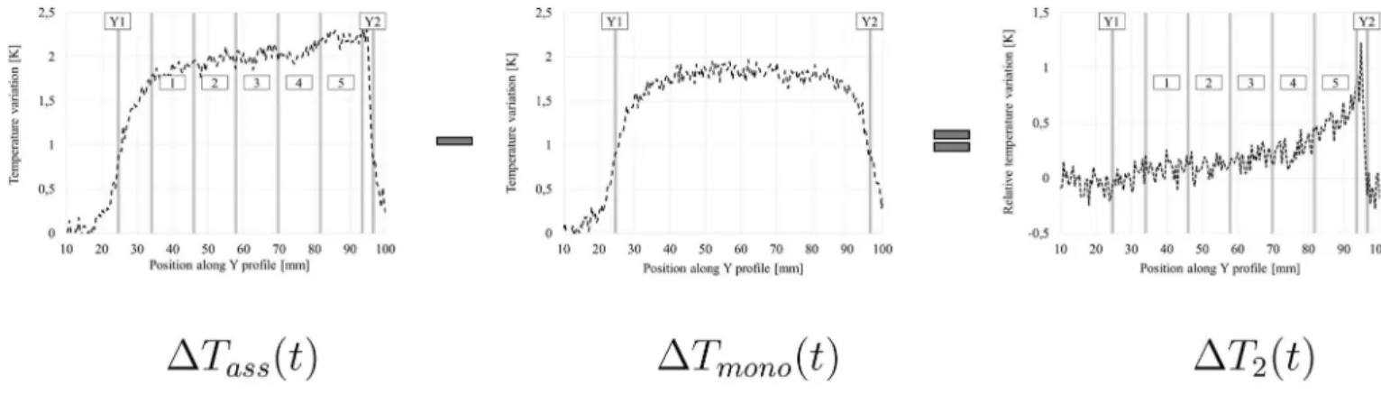
Note finally that some next results, both experimental and simulated, will be based upon a post-processing in order to highlight the thermal response of the adhesive joint and then help in differentiating its specific response. Precisely, the relative temperature ΔT2ðtÞ ¼ ΔTassðtÞ & ΔTmonoðtÞ
is obtained by subtracting from the thermal field variation ΔTassðtÞ of the
repaired assembly the thermal field variation ΔTmonoðtÞ obtained at the
same time t for an equivalent but monolithic (non repaired) sample (same material and same geometry,Fig. 4). Such procedure makes it possible to remove lens edge effects and allows to access to the thermal response of the three shallowest steps (2.3 mm depth within the laminate). Note also that the ΔT2evolution highlights in all cases the thermal peak induced by
the glue overflow (located between step nº5 and point Y2 on ΔT2plots).
3. Joint material design
The objective of this section is to define a new epoxy-based joint material whose additives would improve the detection of bonding defects by the active IRT procedure described before. Given the performance of the model developed before, this numerical tool was used to guide design choices.
3.1. Definition of the joint thermal behaviour
Though many parameters can affect the joint thermal response, the assumption that the thermal conductivity is a significant one can
however be taken[16]. Accordingly, one has considered in simulations an insulating (respectively conductive) behaviour compared to the epoxy matrix obtained by dividing (resp. multiplying) its thermal conductivity by a factor five. Density and specific heat are assumed to remain the same. Moreover, a bonding defect with a width of 20 mm has been numerically created at the second bonding interface (step 4 at a depth of 1.56 mm,Figs. 1 and 5) by replacing the joint properties by those of the air at 20*C (Table 1-a). Note also that results for adhesive bonded
as-semblies without defect (denoted virgin) are also provided as a reference. Let focus on the end of the heating phase (t¼ 12s) for which thermal gradients are the most important. Due to its natural insulating behaviour, the epoxy matrix acts as a thermal barrier and generates a local tem-perature elevation ΔTass higher than that obtained for the monolithic
composite ΔTmono, so ΔT2+ 0, specially where the joint is shallowest[7]
(red area on the left hand side ofFig. 6-a, corresponding to the step nº5 and close to the point Y2). Using a more insulating joint material in-creases such tendency. On the contrary, the conductivity of the joint in the more conductive scenario is greater than the transverse conductivity of the composite ply, leading to a better heat conduction along the X direction (along width of the steps) and along Z direction (in the thick-ness of the assembly). In that case, ΔTass, ΔTmono, leading to a negative
relative temperature (ΔT2, 0, on the right hand side ofFig. 6-a). Since
air captured inside the bonding defect exhibits an insulating thermal behaviour, the local temperature variations induced by this kind of defect are then covered by those of epoxy matrix (which has also an insulating behaviour compared to laminated coupons). Which such configuration, the defect is hidden and IRT may be unreliable to detect it. It is thus more relevant to use a more conductive behaviour for the joint as disturbances generated by the joint interface and bonding defect are of opposite
Fig. 3. Schematic representation of the thermal problem.
Fig. 4. Example of ΔT2ðtÞ post-processing: case of an insulating joint material.
Fig. 5. Constitutive parts of the FE model with bonding defect (points Y1 and Y2 corre-spond to the vertical limits of the heated area).
nature. Simulation ofFig. 6-b clearly illustrates such interest in the event of a defect.
3.2. Choice of conductive additives
Two types of conductive additives commonly used to modify the thermal properties of materials were considered and microstructurally examined by Scanning Electron Microscopy (SEM):
- Alumina ALM-41-01 from SUMITUMO®
(aluminum oxide, Al2O3,
[17–19]), whose particles are spherical with an average diameter of 2 μm (Fig. 7-a),
- Boron nitride CTP8 from SAINT-GOBAIN®
(BN,[13,14,20]), in form of platelets particles with an average size of 8 μm (Fig. 7-b). Properties of these materials are described inTable 1-b. In order to make the best choice among them, one proposes to simulate the thermal response obtained with a composite joint made of epoxy matrix and each of these additives. It is thus necessary to estimate its global thermo-physical properties according to the constituents ones. In considering a Representative Elementary Volume (REV) of the joint with a size upper than those of the particles, numerous schemes aim at predicting the effective behaviour of such composite material. In view of the spherical shape of alumina particles (see Ref.[14]), the law of Maxwell-Garnet appears to be suitable for the estimation of the effective thermal con-ductivity λeqfor the Al2O3loaded epoxy:
λeq¼ λm
2 41þ
3f λa&λm
λaþ2λm
1& f&λa&λm
λaþ2λm
' 3
5 (3)
while the logarithmic of Lichtenecker seems more relevant in case of platelet boron nitride additives:
ln λeq¼ ð1 & f Þln λmþ f ln λa (4)
In equations(3) and (4), λm (respectively λa) denotes the thermal
conductivity of the epoxy matrix (resp. of additives) for a volume fraction
f of additives, effective density and specific heat being deduced by the
classical mixture law. Note finally that simulations have been performed in both cases for a volume fraction f¼ 60% which corresponds to the theoretical maximum rate guaranteeing an homogeneous mixing of constituents [21]. Table 1-c gives related effective properties of the composite joint used for simulations.
The influence of both additive inclusions inside the epoxy matrix is shown onFig. 8. The relative temperature variations ΔT2along the Y
profile confirms that the use of those particles leads to relative temper-ature variations ΔT2, 0 in both cases. However, the responses of
alumina and boron nitride loaded epoxy are clearly distinct, with a higher amplitude obtained for BN. For instance, regarding the step nº5 in the case without defect, the relative temperature variations ΔT2obtained
for BN loaded epoxy joint is almost twice that provided with alumina additives. These results are directly linked to the high thermal conduc-tivity of boron nitride material and of the associated loaded joint. As
Fig. 6. Influence of the joint thermal behaviour: simulated surface temperature variation ΔT (a) (left hand side: insulating behaviour, right hand side: conductive behaviour), relative temperature variation ΔT2along the Y profile (b) at t ¼ 12s.
assumed before, the thermal conductivity thus essentially governs heat flow transmission in the present context. In the presence of a bond defect, the contrast with the virgin assembly is consequently much more important with boron nitride additives, which helps in addressing the detection problem. Accordingly, BN particles have been selected in what follows to elaborate the new joint material.
3.3. Elaboration and characterization of the BN loaded epoxy
The inclusion of boron nitride inside the epoxy matrix requires a special attention during the elaboration process otherwise numerous voids would lead to a foam-type structure (Fig. 9-a). The aim of such procedure is then to ensure the most complete outflow of air bubbles encapsulated between platelet particles and the most homogeneous blending of constituents. In addition, beyond a volume fraction f¼ 8% of boron nitride, the BN loaded epoxy blend exhibits a so important vis-cosity that it is required to use acetone to improve its solubility[14]. Acetone being volatile at 20*C, it is naturally removed during the air
outflow done under vacuum. Moreover, possible traces of acetone do not interfere with the improvement of thermal conductivity, they may even increases it[22]. Following these recommendations allows to optimize the elaboration phase (Fig. 9-b) with an homogeneous repartition of particles and almost no voids (see SEM observation onFig. 9-c). Yet, beyond an additives volume fraction of f¼ 18%, the blend viscosity prevents the air outflow after curing, even with acetone, such volume fraction will thus be considered hereafter.
The introduction of boron nitride particles into the epoxy matrix al-lows a significant enhancement of the conductivity. Indeed, thermal measurement using HOT-DISK®TPS2500S gives λ¼ 0:79Wm&1K&1for
the new joint material (which stands in agreement with the Lichtenecker model), that is an increase of 250% compared to epoxy matrix. It should be noted that the density and the specific heat are little affected by the use of BN additives (respective increase of 14% and 3% compare to epoxy matrix).
4. Infrared investigation of assemblies bonded with the loaded joint
The geometry of studied assemblies remains as before (Fig. 1) and the 0.3 mm thickness joint was calibrated with sheets of Teflon paper placed on the two deepest steps (nº1 and 2). The inferior and superior elemen-tary coupons of both assemblies come from a single layup and were machined at the same time by abrasive water jet. Once the BN loaded epoxy (or epoxy matrix) is applied on the three shallowest steps of the inferior coupon (nº3, 4 and 5), the superior coupon is put down on the assembly and the assembly is hold during the curing process (15 min at 80*C). Accordingly, one can assume a constant thickness of the joint
along the bond line. Moreover, as the duration and amplitude of the thermal load do not allow the heat flow to reach the two deepest steps, the thermal surface field is therefore not affected by the Teflon paper.
The active IRT procedure was applied on defective assemblies including two partially bonded areas accounting for bonding de-fects (Fig. 10):
- a small zone located at the border of the step nº5 (depth of 0.78 mm), denoted defect nº1,
- a wider one covering nearly all the central part of the step nº4 (depth of 1.54 mm), called defect nº2.
Fig. 8. Influence of additives inside the loaded epoxy matrix: simulated surface temperature variation ΔT (a) (left hand side: Al2O3loaded epoxy, right hand side: BN loaded epoxy),
relative temperature variation ΔT2along the Y profile (b) at t ¼ 12s.
In order to highlight the contribution of the new joint material, such preparation has been done for assemblies with both epoxy matrix and BN loaded epoxy.
Using the epoxy matrix does not allow to distinguish the defects response among the thermal results for assemblies, even on the relative temperature variation field ΔT2(Fig. 11-a). Infrared investigation is thus
very limited in that case. On the contrary,Fig. 11-b clearly illustrates the ability of the new joint material to capture the two bonding defects located at different depths. Thermal evolutions along profiles passing through each defect (yellow profile for defect nº1 and orange profile for defect nº2) confirm these conclusions. Moreover, one can identify with the loaded epoxy the spatial location of defect quite precisely. Indeed, the related maximum elevation of ΔT2on the specimen surface appears in
the corresponding zone of defective interfaces, respectively step nº5 for
defect nº1 obtained after 5s of heating (Fig. 11-c), and step nº4 for defect nº2 after 10s of heating (Fig. 11-d). These ΔT2elevations are induced by
defects whereas thermal peaks at around Y¼ 95 mm onFig. 11-c and d correspond to the glue overflow at the sample surface denoted onFig. 1
(precisely these latter values differ betweenFig. 11-c and d according to the heating time and the position of the Y profile in the heated area). In agreement with numerical simulations, the introduction of boron nitride additives seems thus a relevant design option to improve the detection capacity of infrared techniques.
5. Conclusions
The original approach proposed in this study, based on material design, brings a clear contribution to experimental mechanics and specially to the non destructive testing of bonded interfaces inside composite materials. Using a numerical model of the thermal problem has led to the definition of a new epoxy-based joint material including additives that enhances the IRT detection capacity. In the present study, experimental results on defective bonded assemblies show the significant interest of the introduction of boron nitride particles into the epoxy matrix to capture bonding defects. It should be noted that this certainly can be further improved by optimizing the elaboration process (leading to higher volume fraction or using more efficient types of additives) and the thermographic data processing to better highlight defect (using filtering procedures for instance). Moreover, the complete validation of such strategy for the analysis of engineering interfaces now requires the characterization of the influence of additives inclusion on the matrix mechanical behaviour and the definition of the detection limit size of the technique.
Fig. 10. Preparation of the tested assembly.
Fig. 11. Experimental relative temperature variation ΔT2for defective bonded assemblies according to the joint material: ΔT2fields for epoxy matrix (a) and BN loaded epoxy (b), ΔT2
Acknowledgements
The authors would like to show their gratitude to the French Midi-Pyr!en!ees Region who supported this research project.
References
[1] Adams RD. Non destructive testing. In: Da Silva LFM, €Ochsner A, Adams RD, editors. Handbook of adhesion technology. Berlin: Spring-Verlag; 2011. p. 1049–69. [2] Adams RD, Drinkwater BW. Nondestructive testing of adhesively-bonded joints.
NDT E Int 1997;30:93–8.
[3] Baker A, Gunnion JA, Wang J. On the certification of bonded repairs to primary composite aircraft components. J Adhes 2015;91:4–38.
[4] Gao B, Woo W, Tian G. Electromagnetic thermography nondestructive evaluation: physics-based modeling and pattern mining. Sci Rep 2016;6:25480.https:// doi.org/10.1038/srep25480.
[5] Palumbo D, Galietti U. Damage investigation in composite materials by means of new thermal data processing. Strain 2016;52:276–85.
[6] Lopez F, Ibarra-Castanedo C, De Paulo Nicolau V, Maldague X. Optimization of pulsed thermography inspection by partial least-squares regression. NDT E Int 2014;66:128–38.
[7] Barus M, Welemane H, Collombet F, Pastor ML, Cantarel A, Crouzeix L, et al. Bonded repair issues for composites: an investigation approach based on infrared thermography. NDT E Int 2017;85:27–33.
[8] Adams RD. The non destructive evaluation of bonded structures. Constr Build Mater 1990;4:3–8.
[9] Yan D, Drinkwater BW, Neild SA. Measurement of the ultrasonic nonlinearity of kissing bonds in adhesive joints. NDT E Int 2009;42:459–66.
[10] Germaneau A, Doumalin P, Dupr!e JC. Comparison between X-ray micro-computed tomography and optical scanning tomography for full 3D strain measurement by digital volume correlation. NDT E Int 2008;41:407–15.
[11] Nielsen SF, Poulsen HF, Beckmann F, Thorning C, Wert JA. Measurements of plastic displacement gradient components in three dimensions using marker particles and synchrotron X-ray absorption microtomography. Acta Mater 2003;51:2407–15.
[12]Ju!arez D, Ferrand S, Fenollar O, Fombuena V, Balart R. Improvement of thermal inertia of styrene-ethylene/butylene-styrene (SEBS) polymers by addition of microencapsulated phase change materials (PCMs). Eur Polym J 2011;47:153–61. [13]Zhou W, Qi S, An Q, Zhao H, Liu N. Thermal conductivity of boron nitride
reinforced polyethylene composites. Mater Res Bull 2007;42:1863–73. [14]Zhu B, Ma J, Wu J, Yung KC, Xie CS. Study on the properties of the epoxy-matrix
composites filled with thermally conductive AlN and BN ceramic particles. J Appl Polym Sci 2010;118:2754–64.
[15]Germain P, Nguyen QS, Suquet P. Continuum thermodynamics. J Appl Mech 1983; 50:1010–20.
[16]Li J, Xue P, Ding W, Han J, Sun G. Micro-encapsulated paraffin/high-density polyethylene/wood flour composite as form-stable phase change material for thermal energy storage. Sol Energ Mat Sol C 2009;93:1761–7.
[17]Das S, Putra N, Roetzel W. Temperature dependence of thermal conductivity enhancement for nanofluids. Am Soc Mech Eng 2003;125:567–74.
[18]Xie H, Wang J, Xi T, Liu Y, Ai F, Wu Q. Thermal conductivity enhancement of suspensions containing nanosized alumina particles. J Appl Phys 2002;91:4568–72. [19]Zhou W, Qi S, Tu C, Zhao H, Wang C, Kou J. Effect of the particle size of Al2O3on
the properties of filled heat-conductive silicone rubber. J Appl Polym Sci 2007;104: 1312–8.
[20]Gaska K, Rybak A, Kapusta C, Sekula R, Siwek A. A study of thermal conductivity of boron-nitride epoxy-matrix composite. In: Proceeding of EECM-15 conference. Venice; June, 2012.
[21]Lee GW, Park M, Kim J, Lee JI, Yoon HG. Enhanced thermal conductivity of polymer composites filled with hybrid filler. Compos Part A Appl S 2006;37: 727–34.
[22]Xu Y, Chung DDL. Increasing the thermal conductivity of boron nitride and aluminum nitride particle epoxy-matrix composites by particle surface treatments. Compos Interface 2000;7:243–56.
[23]Marchio D, Reboux P. Introduction aux transferts thermiques. Paris: Mines ParisTech Les Presses “Les cours de l’!ecole des mines”; 2008. 210pp.
[24] Ceramic materials and ceramic components. June, 2017.http://accuratus.com/ alumox.html.