HAL Id: tel-02967502
https://tel.archives-ouvertes.fr/tel-02967502
Submitted on 15 Oct 2020HAL is a multi-disciplinary open access archive for the deposit and dissemination of sci-entific research documents, whether they are pub-lished or not. The documents may come from teaching and research institutions in France or abroad, or from public or private research centers.
L’archive ouverte pluridisciplinaire HAL, est destinée au dépôt et à la diffusion de documents scientifiques de niveau recherche, publiés ou non, émanant des établissements d’enseignement et de recherche français ou étrangers, des laboratoires publics ou privés.
software Architecture uNderstanding and Evolution
Alexandre Le Borgne
To cite this version:
Alexandre Le Borgne. ARIANE : Automated Re-Documentation to Improve software Architecture uNderstanding and Evolution. Other [cs.OH]. IMT - MINES ALES - IMT - Mines Alès Ecole Mines - Télécom, 2020. English. �NNT : 2020EMAL0001�. �tel-02967502�
THÈSE POUR OBTENIR LE GRADE DE DOCTEUR
ÉCOLE NATIONALE SUPÉRIEURE DES MINES D’ALÈS (IMT MINES ALÈS)
En Informatique
I2S – Information, Structures, Systèmes
Portée par l’Université de Montpellier
Unité de recherche LGI2P
ARIANE: Automated Re-documentation to Improve
software Architecture uNderstanding and Evolution
Présentée par Alexandre LE BORGNE
Le 24 Janvier 2020
Sous la direction de David DELAHAYE
et Marianne HUCHARD
Devant le jury composé de
Nicolas ANQUETIL, MCF HDR, INRIA, Univ. Lille Nicole LEVY, PR, CNAM Paris
Nicolas BELLOIR, MCF, IRISA, Ecoles de St-Cyr Coëtquidan Mourad OUSSALAH, PR, LINA, Univ. Nantes
David DELAHAYE, PR, LIRMM, Univ. Montpellier Marianne HUCHARD, PR, LIRMM, Univ. Montpellier Christelle URTADO, MA IMT HDR, LGI2P, IMT Mines Alès Sylvain VAUTTIER, MA IMT HDR, LGI2P, IMT Mines Alès
Rapporteur Rapporteur, Présidente Examinateur Examinateur Co-directeur Co-directrice Co-encadrante Co-encadrant
iii
“En raison d’un appel à la grève émanant de la CGT, nous ne sommes pas en mesure de diffuser l’intégralité de nos programmes habituels. Nous vous prions de nous en excuser.”
v
Abstract
All along its life-cycle, a software may be subject to numerous changes that may affect its coherence with its original documentation. Moreover, despite the general agreement that up-to-date documentation is a great help to record design decisions all along the software life-cycle, software documentation is often outdated. Architecture models are one of the ma-jor documentation pieces. Ensuring coherence between them and other models of the soft-ware (including code) during softsoft-ware evolution (co-evolution) is a strong asset to softsoft-ware quality. Additionally, understanding a software architecture is highly valuable in terms of reuse, evolution and maintenance capabilities. For that reason, re-documenting software becomes essential for easing the understanding of software architectures. However archi-tectures are rarely available and many research works aim at automatically recovering soft-ware architectures from code. Yet, most of the existing re-documenting approaches do not perform a strict reverse-documenting process to re-document architectures "as they are im-plemented" and perform re-engineering by clustering code into new components. Thus, this thesis proposes a framework for re-documentating architectures as they have been de-signed and implemented to provide a support for analyzing architectural decisions. This re-documentation is performed from the analysis of both object-oriented code and project deployment descriptors. The re-documentation process targets the Dedal architecture lan-guage which is especially tailored for managing and driving software evolution. Another highly important aspect of software documentation relates to the way concepts are ver-sioned. Indeed, in many approaches and actual version control systems such as GitHub, files are versioned in an agnostic manner. This way of versioning keeps track of any file history. However, no information can be provided on the nature of the new version, and especially regarding software backward-compatibility with previous versions. This thesis thus proposes a formal way to version software architectures, based on the use of the Dedal architecture description language which provides a set of formal properties. It enables to automatically analyze versions in terms of substitutability, version propagation and pro-poses an automatic way for incrementing version tags so that their semantics corrrespond to actual evolution impact. By proposing such a formal approach, this thesis intends to pre-vent software drift and erosion. This thesis also proposes an empirical study, to validate our approach named ARIANE, based on both re-documenting and versioning processes on numerous versions on an enterprise project taken from GitHub.
vii
Remerciements
En premier lieu je tiens à remercier Jacky Montmain, directeur du Laboratoire de Génie In-formatique et d’ingénierie de Production (LGI2P) de l’IMT Mines Alès, de m’avoir accueilli au sein de l’équipe. Son écoute, sa patience et son dévouement pour les doctorants du LGI2P m’auront permis de réaliser cette thèse dans les meilleures dispositions.
Je tiens ensuite à remercier l’ensemble des membres du jury qui ont accepté d’évaluer mon travail et qui, malgré un report impromptu de la soutenance dans un climat social tendu, se sont mobilisés pour que je soutienne dans les meilleures conditions possibles. Je remer-cie particulièrement Madame Nicole Lévy d’avoir présidé le jury et rapporté ma thèse. Je remercie également Monsieur Nicolas Anquetil d’avoir lui aussi accepté de rapporter ma thèse. De même, je remercie Monsieur Mourad Oussalah d’avoir accepté d’examiner mon travail de thèse. Enfin je remercie Monsieur Nicolas Belloir qui, en sa qualité d’examinateur et ancien de mes enseignants, m’aura accompagné pendant mes études d’informatique et ce jusqu’à ma soutenance de thèse.
Je tiens à présent à remercier mon équipe encadrante qui m’a fait confiance et sans laquelle je ne serais pas arrivé au bout de ce travail. Leurs qualités tant professionnelles qu’humaines m’auront porté tout au long de cette thèse. Ainsi je remercie mes directeurs de thèse : Mari-anne Huchard qui a su apporter sa sagesse dans les réunions de travail, et toujours beaucoup de bienveillance envers ses doctorants ; David Delahaye qui, malgré ou grâce à son esprit formel, a toujours agrémenté nos échanges d’une bonne dose d’humour. Bien sûr je remercie particulièrement mes encadrants de proximité qui m’ont suivi de près au LGI2P : Christelle Urtado d’avoir toujours su me motiver pendant cette thèse et dont la justesse des conseils m’aura aidé à y voir plus clair aux moments les plus déterminants ; Sylvain Vauttier pour les éclairages souvent techniques et théoriques qu’il m’a apporté pendant cette thèse. Aussi, je tiens à remercier mes encadrants pour leur disponibilité et la facilité que nous avons eu à pouvoir échanger et ainsi avancer ensemble.
Je remercie aussi l’ensemble du personnel technique et administratif du LGI2P et plus par-ticulièrement Claude Badiou et Edith Teychené pour leur gentillesse et leur abnégation. Je remercie aussi l’ensemble des enseignants-chercheurs, doctorants, post-doctorants et in-génieurs avec qui j’ai toujours eu plaisir à échanger. De même je remercie l’ensemble des stagiaires, Paul Heidmann, Guillaume André et Valentin Colas qui m’auront aidé à mener mon projet à bien. Je tiens également à remercier mes collègues et amis : Behrang, Quentin, Pierre-Antoine, Thibault, Emilie, Clément, Pascale, Roland, Perrine, Lucie, Frank et tous ceux avec qui j’ai eu l’occasion de passer de bons moments, et qui ont été d’un grand sou-tien pendant ces trois ans.
Enfin je remercie ma famille, pour son amour et son soutien indéfectible qui m’auront porté jusque-là. Je remercie aussi plus particulièrement Cécile que j’ai le bonheur d’avoir à mes côtés depuis le début de ma thèse – cœur avec les doigts –.
ix
Contents
Abstract v
Remerciements vii
1 Introduction 1
1.1 General context of component-based software engineering . . . 1
1.2 Documenting and versioning component-based software architectures issues 2 1.3 Thesis proposal and contribution . . . 2
1.4 Outline of the thesis. . . 4
2 Context and motivations 5 2.1 Component-based software engineering . . . 5
2.1.1 Component-based software life-cycle . . . 6
2.1.2 Summary . . . 9
2.2 Component-based software architectures . . . 10
2.2.1 Basic concepts in software architecture . . . 10
2.2.2 Architecture modeling . . . 12
2.2.3 Architecture evolution . . . 13
2.2.4 Architecture analysis . . . 15
2.3 The Dedal architecture model . . . 16
2.3.1 The Dedal abstract architecture specification level . . . 18
2.3.2 The Dedal concrete architecture configuration level . . . 19
2.3.3 The Dedal instantiated architecture assembly level . . . 19
2.3.4 Dedal formal rules . . . 20
2.4 Motivations for re-documenting and versioning architectures . . . 21
2.5 Conclusion . . . 21
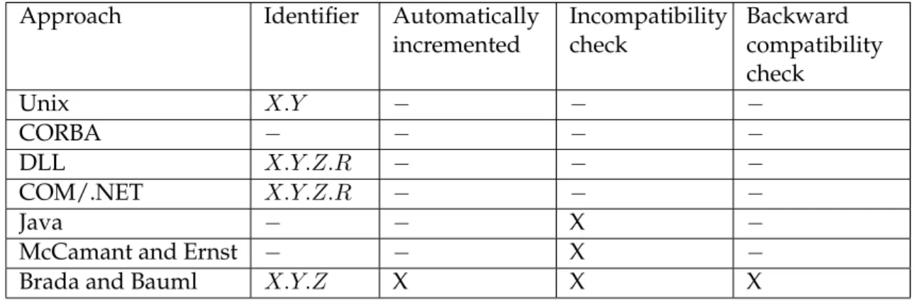
3 State of the art 23 3.1 Study on component-based software architecture versioning . . . 24
3.1.1 Versioning components . . . 25
3.1.2 Model evolution and versioning . . . 28
3.1.3 Versioning component-based software architectures . . . 32
3.1.4 Discussion . . . 33
3.2 Architecture evolution approaches . . . 35
3.2.2 Darwin . . . 36
3.2.3 Wright / Dynamic Wright . . . 36
3.2.4 ArchWare . . . 36
3.2.5 xADL. . . 37
3.2.6 Mae. . . 37
3.2.7 SOFA 2.0 . . . 37
3.2.8 Synthesis and comparison . . . 38
3.3 Retrieving architecture documentation and software maintainability . . . 40
3.3.1 Software re-documentation approaches . . . 40
3.3.2 Software architecture reconstruction approaches . . . 41
3.4 Conclusion . . . 44
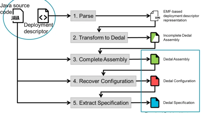
4 Re-documenting component-based software architectures 47 4.1 Process overview . . . 48
4.1.1 Inputs . . . 48
4.1.2 Process . . . 50
4.1.3 Output . . . 51
4.2 Re-documenting architectures . . . 52
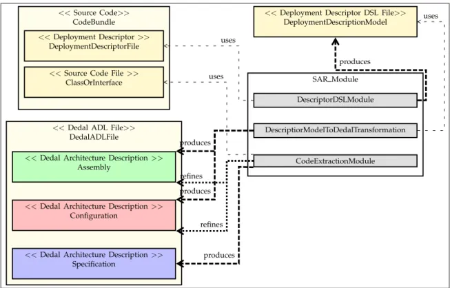
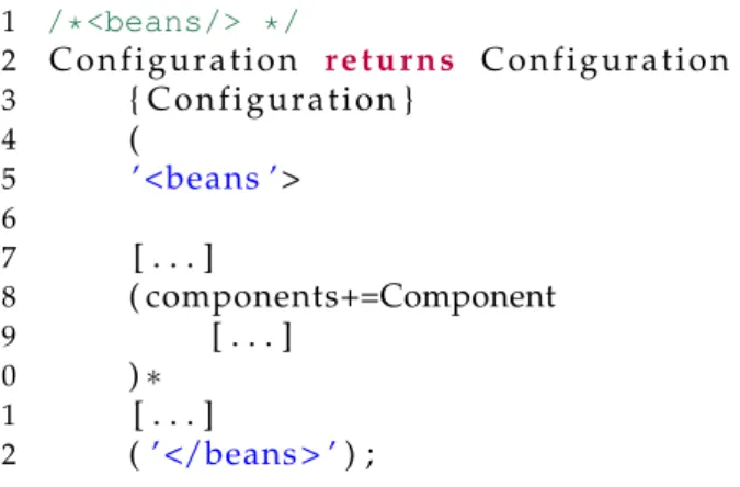
4.2.1 SpringDSL, a DSL for mapping Spring Concepts . . . 53
4.2.2 Model to model transformation: from descriptor model to partial Dedal architecture model . . . 56
4.2.3 Extracting information from the object-oriented code . . . 57
4.2.4 Re-documenting Assembly . . . 58
4.2.5 Re-documenting Configuration from Assembly . . . 63
4.2.6 Re-documenting Specification . . . 64
4.3 Generalization . . . 69
4.3.1 Discussion . . . 69
4.3.2 Algorithm . . . 70
4.4 Conclusion . . . 72
5 Versioning component-based software architectures 73 5.1 Semantics in versioning . . . 74
5.1.1 Definitions and notations . . . 74
5.1.2 Traditional versioning . . . 75
5.1.3 Problems of current version management systems . . . 76
5.1.4 Substitutability-based versioning. . . 77
5.2 Identification of architectural changes, version characterization . . . 81
5.2.1 Identifying and categorizing component-based architecture changes . 81 5.2.2 Version meta-model . . . 84
5.2.3 Three-leveled version meta-model . . . 85
5.3 Predicting version propagation . . . 86
5.3.1 Typology of architectural change impact . . . 86
xi
5.4 Example of three-leveled architecture versioning . . . 91
5.5 Conclusion . . . 94
6 Case study and implementation 97 6.1 Implementation of re-documentation and versioning approaches . . . 98
6.1.1 Overview of DedalStudio . . . 98
6.1.2 Implementation of the re-documentation module . . . 99
6.2 Implementation of architecture versioning. . . 104
6.3 Experimentation and evaluation . . . 106
6.3.1 Case study: Broadleaf Commerce. . . 107
6.3.2 Experimentation . . . 107
6.4 Conclusion . . . 113
7 Conclusion and Perspectives 115 7.1 Contributions . . . 115
7.1.1 Software re-documentation contributions . . . 116
7.1.2 Software architecture versioning contributions . . . 116
7.2 Limitations and perspectives . . . 117
7.2.1 Software re-documentation perspectives . . . 117
7.2.2 Software architecture versioning perspectives . . . 118
7.2.3 Experimental perspectives. . . 118
A XText-based Spring implementation 119 B SpringToDedal QVTo transformation 139 C Re-documentation algorithm 161 D Papers and tools 173 D.1 Released tools . . . 173
D.2 Published papers . . . 173
E Résumé en français 175
xiii
List of Figures
2.1 Waterfall development model . . . 7
2.2 The CBSD process . . . 8
2.3 Benett an Rajlich process model for evolution [BR00a] . . . 14
2.4 Reuse development process [Zha10] . . . 17
2.5 Component interfaces (adapted from [Som11]) . . . 17
2.6 Dedal architecture levels for a Home Automated Software [Mok+16a] . . . . 18
4.1 Process of Component-Based Software Architecture Reconstruction . . . 48
4.2 Home Automation Software (HAS): XML-based Spring configuration. . . 49
4.3 HAS: UML diagram . . . 49
4.4 SpringDSL representation of HAS Spring deployment descriptor . . . 50
4.5 HAS: Dedal incomplete Assembly after step 2 . . . 50
4.6 HAS: Dedal Reconstructed Architecture Levels . . . 51
4.7 Example of bean declaration with dependency injection . . . 51
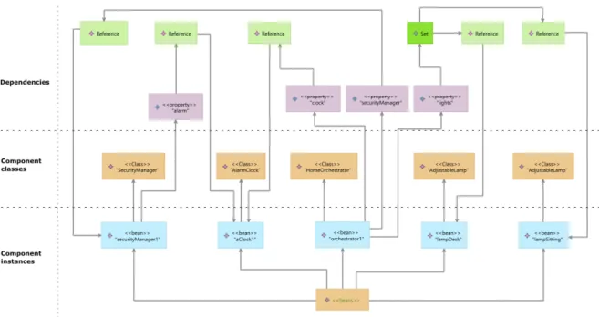
4.8 Three-level view of reconstructed Dedal architecture. . . 51
4.9 Structure of the re-documentation module. . . 52
4.10 Configuration Xtext-based implementation . . . 53
4.11 Component Xtext-based implementation . . . 54
4.12 Reference Xtext-based implementation . . . 54
4.13 Excerpt of the SpringDSL Metamodel . . . 55
4.14 Dedal Metamodel Sub-part for M2M transformation. . . 56
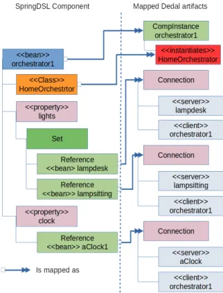
4.15 Mapping SpringDSL artifacts into Dedal artifacts. . . 57
4.16 A single provided interface is exposed . . . 58
4.17 All provided interface are exposed . . . 58
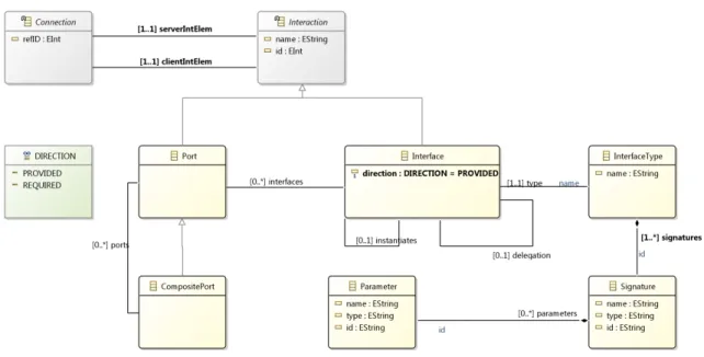
4.18 Dedal Interactions Meta-Model . . . 60
4.19 Mapping Dedal Interfaces from type hierarchy . . . 62
4.20 Example of Role Hierarchy based on the HAS Example . . . 65
4.21 Identifying realized Component Roles . . . 67
4.22 Connecting Component Roles . . . 68
4.23 HAS: Reconstructed Specification . . . 68
5.1 Traditional versioning . . . 75
5.2 Substitutability-aware versioning . . . 77
5.3 Multilevel component versioning . . . 78
5.5 Multilevel architecture versioning . . . 79
5.6 Finding transitively implemented Specifications using substitutability . . . . 80
5.7 Dedal three-leveled architecture versioning . . . 81
5.8 Metamodel for semantic versioning . . . 85
5.9 Dedal versionable artifacts . . . 85
5.10 Base-Case: Functionality Connection Within a Three-Level Component-Based Architecture . . . 87
5.11 Propagating version at three architecture levels . . . 91
5.12 HAS type hierarchy extract . . . 92
5.13 HAS components version graph . . . 92
5.14 HAS initial architecture. . . 93
5.15 HAS: component instance addition . . . 94
5.16 HAS: component role replacement . . . 95
5.17 HAS: version graph . . . 95
6.1 DedalStudio (and output of the component-based-hierarchy-builder module) . . 99
6.2 Re-documentation module structure . . . 100
6.3 Example of built hierarchy from Java project (output of HierarchyBuilder mod-ule) . . . 102
6.4 Example of SpringDSL file . . . 103
6.5 Dedal model comparison module . . . 104
6.6 Re-documented components and Java classes in function of architecture ver-sions . . . 108
6.7 Component instances and XML Spring files in fonction of architecture versions110 6.8 Version increment accuracy . . . 111
6.9 Version increment mistakes . . . 111
xv
List of Tables
3.1 Component versioning approaches . . . 34
3.2 Architecture versioning approaches . . . 35
3.3 Software evolution approaches: versioning integration . . . 39
3.4 Existing software architecture reconstruction approaches . . . 44
4.1 Java access level modifiers [Java] . . . 62
5.1 Substitutability-based architectural changes . . . 83
5.2 Replacing Components: Providing a Functionality . . . 88
5.3 Replacing Components: Requiring a Functionality . . . 90
1
Chapter 1
Introduction
This chapter gives a brief introduction of the context this thesis stands in, the problem which is addressed, the proposed contributions, and presents the outline of the manuscript.
1.1
General context of component-based software engineering
Because of the constantly increasing complexity of software systems, new needs have ap-peared from early ages of software engineering for advantageously producing and main-taining software reducing costs. This is why component-based software engineering has emerged in late 1990’s as a sub-discipline of software engineering, which promises to ad-dress those issues. Component-based software engineering advocates a specific software development approach centered on component reuse [Som11]. This discipline proposes a set of methods and models which aim at improving component-based software devel-opment (CBSD). CBSD approaches give a methodological support to enhance reusability by providing guidelines to assemble already developed decoupled software components. Those component are stored in repositories and referred as Off-The-Shelf components. It therefore avoids building entire systems from scratch, taking advantage of past develop-ments. It significantly decreases development costs and time-to-market preserving quality of software components [CL02].As an essential part of CBSD, software architectures give an abstraction of the software struc-ture and expose the way that it is supposed to evolve [Gar00]. Software architecture models therefore contain the list of the elements that are part of the system and the information about how those elements are connected one to another. As software architectures are ab-straction of software themselves, they capture the design decisions, which occur during the development process. This level of abstraction helps to reason in terms of architectural element evolution instead of source code evolution, which can be more difficult to under-stand [GDT06].
However, despite CBSD processes have been improved over years, some issues remain that concern software architecture maintenance and evolution [BCL12]. As part of those issues, we can highlight the evolution of component-based software architecture documentation,
which often becomes obsolete [DP09], and the versioning of software architectures, which is surprisingly not much discussed in literature.
1.2
Documenting and versioning component-based software
archi-tectures issues
Despite a lot of work [DP09] in the field of software engineering for improving the documen-tation of software systems, software evolution still leads to design decision loss. Software evolution without co-evolution of software models is but the ruin of architectures. Then, most of the time, design decisions are lost due to architectural drift or erosion [GMW97]. We argue that the information that has been lost during software evolution must there-fore be recovered prior to performing any crucial evolution task. A lot of work exists that addresses this issue by generally proposing approaches that re-engineer software architec-tures [DP09]. Very few of these approaches only intend to re-document component-based architectures "as they are implemented". Moreover, none of these approaches consider more than two abstraction levels whereas previous work on Dedal ADL has shown that three ab-straction levels are necessary to handle the global software life-cycle [Zha+12b]. However, such documentation is essential for performing software evolution.
Additionally, during its evolution, a software is subject to numerous changes that lead to numerous versions of the software. Then, in order to keep track of the software history, it is necessary to identify its successive versions. Despite abundant literature in the field of databases and software versioning, little work even intend to address this issues in the field of component-based software architectures. There are even fewer approaches that propose a way to version components and / or architectures by using verifiable semantics. However, such semantics are needed in order to well identify software versions since a wrong version identifier may misguide software architects.
1.3
Thesis proposal and contribution
As a contribution, this thesis proposes to answer the following research questions:
• RQ1. Is it possible to re-document multi-abstraction level component-based architec-tures from source code, and is it possible to retrieve abstract design decisions from this re-documentation?
• RQ2. How to introduce semantics in component and architecture versioning?
• RQ3. Are such re-documenting and / or versioning approaches suitable for large soft-ware systems?
• RQ4. Is it possible to identify drift and / or erosion situations by re-documenting and analyzing software versions?
1.3. Thesis proposal and contribution 3
In order to improve software evolution, documentation must remain consistent with the actual software implementation and deployment all along its life-cycle. Moreover, this doc-umentation must cover the software development main steps, which are the specification, the implementation, and the deployment. However, despite the well-known benefits of an up-to-date documentation, it is often not consistent with the actual state of the software be-cause of an undocumented evolution. Performing evolution tasks may therefore be difficult in this case. This is why this thesis proposes an approach to re-document software architec-tures from raw source code. This approach is based on Dedal [Zha+12b; Mok+16a], which provides three architecture levels for tracking main steps of software life-cycle. Moreover, it also provides a formalized basis for calculating automated evolution plan. This formalism especially ensures the three architecture level coherence. In other words, it ensures that the description of deployment is consistent with the description of implementation, and finally that the description of implementation is consistent with the description of the specification. Dedal therefore provides a good support for re-documenting software in order to retrieve suitable software evolution capabilities. This contribution answers research question RQ1. Another contribution of this thesis consists in using formal rules based on type theory [Aré+07; Aré+09] to characterize component and architecture differences in terms of back-ward compatibility. The characterization of changes is made from a change analysis impact study. This study is based on formal Dedal architectural rules and allows us to derive a set of rules to characterize substitutable and not substitutable changes. Change impact analysis also makes it possible to derive rules of version propagation among the three Dedal archi-tecture levels in order to preserve architectural consistency. This contribution also includes a proposal to automatically change version identifiers accordingly to the kind of version that is identified. This part of the thesis answers research question RQ2.
Finally, the last contribution of this thesis is the set of tools that have been developed in order to answer research questions RQ3 and RQ4. Those tools can be fully integrated into the eclipse ecosystem and DedalStudio, which is our CASE (Computer-Aided Software Engi-neering) tool that supports the Dedal ADL. The tools have been released online (see GitHub1 and LGI2P’s web site2) and consist of the following components:
• SpringDSL is our implementation of XML Spring [Joh+04] grammar into the EMF3 environment.
• HierarchyBuilder proposes to build the entire type hierarchy of a Java project including required libraries where traditional code parsers only consider source code.
• component-based-hierarchy-builder re-documents three leveled Dedal architectures from source code and Spring framework.
• ProjectComparator calculates and characterizes architectural differences between two versions of a Dedal architecture model.
1http://www.github.com/DedalArmy 2http://www.dev.lgi2p.mines-ales.fr/ariane/
• DiffAnalyzer analyzes found differences and checks for architectural deviation situa-tions.
In addition to the main tooling contributions, we released the previously developed Dedal-Studio modules as eclipse plugin online to ease its installation into the eclipse environment. Next section presents the outline of the thesis.
1.4
Outline of the thesis
The thesis is organized as follows:• Chapter 2introduces in detail the context of this thesis. It presents the component-based software development process and the component-component-based software architecture concept. It also introduces the Dedal architecture description language.
• Chapter3introduces the state of the art of this thesis. It consists of three parts. The first one is a survey of versioning approaches in literature in order to identify limits of these approaches especially in term of formalization and automation of version identifica-tion. The second one concerns formal architecture evolution approaches to highlight their limits in terms of component and architecture versioning. Finally, the last one is a survey that compares re-documentation and reconstruction approaches, and justifies our choice for re-documenting software as three-leveled component-based architec-ture with the Dedal ADL.
• Chapter4introduces the proposed approach and algorithm for re-documenting compo-nent-based architectures from source code. It defines the different steps that lead from an undocumented software to a three-level description of it.
• Chapter5introduces an approach for managing version identification in software his-tories. This identification is based on a formal architecture impact analysis and pro-poses rules for automatically characterizing component and architecture versions. • Chapter6 presents the implementation of our approach and introduces a study that
has been conducted on more than 200 versions of an enterprise open-source project to re-document it and check the soundness of its version identification in terms of architecture erosion / drift situation identification.
• Chapter 7finally summarizes the thesis contributions and discusses limitations and perspectives to this work.
5
Chapter 2
Context and motivations
Contents
1.1 General context of component-based software engineering . . . . 1
1.2 Documenting and versioning component-based software architectures issues . . . . 2
1.3 Thesis proposal and contribution . . . . 2
1.4 Outline of the thesis . . . . 4
As introduced in Chapter1, the contribution of this thesis takes place in the field of Compo-nent-Based Software Engineering (CBSE). More precisely, this thesis focuses on Component-Based Software Architectures re-documention and versioning. This chapter is designed to give a deeper understanding of the context this thesis stands in. As it takes places in the continuity of Zhang’s thesis [ZUS10] and Mokni’s thesis [Mok15], it is positioned in the same context and therefore follows the same outline as Zhang’s and Mokni’s thesis context.
2.1
Component-based software engineering
Component-Based Software Engineering appeared in late 1990’s as a subdiscipline of the wide Software Engineering field. CBSE provides developers with methods, models and guidelines oriented towards component-based systems [Pre97]. CBSE then emerged as a reuse-based approach to software development [Som11]. The goal of CBSE, is to provide keys for producing software from already developed components in opposition with de-velopments realized from scratch. The motivation of such approach is to meet software industry concerns about the reduction of costs, development time to meet customer needs, software maintainability and reliability [SGM02]. Thus, CBSE quickly took a great place in the field of Software Engineering. This success is due to some important factors. First of all, software becomes more and more complex and provides more functionality. The use of soft-ware components makes it possible to meet the need of producing more functionalities with the same investment in terms of costs and time [Pre97]. Next, until CBSE, traditional ap-proaches fail at supporting reuse. As stated by Sommerville [Som11], abstract unit descrip-tions such as components can be considered as standalone service providers while object classes are too much detailed and specific. Last but not least, software constantly evolves
and so do its requirements, which means that a support for easy change is needed. Council and Heineman [CH01] identified the three following major concerns of CBSE:
• to support reusable component entities,
• to support development of systems as component assemblies,
• and to ease maintainability and upgrading of such systems by being able to customize and replace their components.
However, despite the well founded benefit of such goals, achieving them in practice can be very challenging and then improving reuse processes is tedious [Pre97]. This difficulty is even emphasized in component-based software evolution practice, especially after software deployment. Thus, for further understanding, it is necessary to consider component-based software life-cycle.
2.1.1 Component-based software life-cycle
Before the concept of component-based software life cycle is introduced, it is important to understand most global software development approaches.
2.1.1.1 Traditional software development processes
The waterfall model is an historic development model that has been proposed by Royce in 1970 [Roy87]. Most of the iterative software development approaches are based on the same activities than the waterfall model [Som11]. Those activities are shown in Figure2.1and are as follows:
1. Requirement definition: During this phase, the goals of the system are established. At the end of this phase, a specification of the system that complies with the realiza-tion of the goals is proposed. The specificarealiza-tion defines funcrealiza-tional and non-funcrealiza-tional requirements.
2. System and software design: During this phase, the software is designed accordingly to the specification that has been produced at the previous phase. This design im-plies to identify and describe a conceptual and technical solution for the software to develop. Thus an architecture that describes the software is proposed.
3. Implementation and unit testing: This phases intends to produce an executable soft-ware that corresponds to the previously proposed design. Implementation can be composed of smaller units. The units are then verified and tested to meet their speci-fication.
4. Integration and system testing: During this phase, system units are integrated and the complete system is verified, validated, and finally released.
2.1. Component-based software engineering 7
5. Operation and maintenance: A system in operation needs continuous support and maintenance. This continuous support may imply to loop on previous waterfall phases for adding new functionalities, fixing bugs. . .
6. Retirement and disposal: This phase is often omitted in life-cycle models since it is implicit. It consists in the phasing out of the system that can either be replaced or completely terminated.
FIGURE2.1: Waterfall development model
According to Sommerville [Som11], the waterfall model clearly separates the different phases of the software development process and the main advantage of its model is that phases do not overlap and documentation is incrementally produced and enriched. Such a develop-ment model is more suitable for small projects which requiredevelop-ments are well understood. However, such model is not appropriate to adapt to changing customer requirements. Such an approach is not responsive since commitments must be made early in the development process while in such models, results are produced very late [Som11].
2.1.1.2 Agile software development methods
In order to improve responsiveness of development processes, agile methods emerged in the 1990’s. They support fast software development and are more adaptable to requirement change. They were primarily meant to support fast iterative development of business appli-cations with short release cycles [Som11]. A group of practitioners has established in 2001 a consensus named the manifesto of agile software. This consensus sets the values of agile methods1. The manifesto argues for the following four values:
• Individuals and interactions over processes and tools. • Working software over comprehensive documentation. • Customer collaboration over contract negotiation.
• Responding to change following a plan.
Agile methods are iterative methods that emphasize incremental development. They en-courage active collaboration with customers into the development process for feedback and to ease requirement changes even after software delivery [Som11]. However, the main draw-back of such methods resides in the fact that they depend too much on individual person-alities. Developers may not be willing to bear the pressure of such processes, which may be intense. On the other hand, customers may no be willing to spend the time that is necessary to make those development processes valuable [Som11]. In addition, in such development processes, prioritizing changes might be a difficult task when the process involves too many stakeholders [Som11]. Thus, agile methods are well adapted to small and medium-sized systems without the risks associated to large, complex and critical systems [Som11].
2.1.1.3 Component-based software development processes
The main purpose of Component-Based Software Development (CBSD) is to build entire systems from preexisting components. Thus, there are two consequences on software de-velopment processes [CCL05]. The first consequence is that software development by com-ponent reuse is separated from comcom-ponent development. In CBSD processes, comcom-ponents need to be already developed at the start of the process. Second, the development process must include a component identification phase [Som11].
FIGURE2.2: The CBSD process
CBSD activities are introduced in Figure2.2and are as follows:
1. Requirements: Requirements can be defined in the form of abstract component types that describe the functionalities of the system. In a component-based approach, the definition of requirements must take into account the ability to develop the system
2.1. Component-based software engineering 9
with existing components. If possible, the system is realized using preexisting soft-ware components, otherwise, new components have to be developed or requirements might change to meet the available component resources [CCL05].
2. System design: This phase is designed to define a complete architecture of the system with refined component types that are fulfilled by existing software components. As in the previous phase, components are reused according to their availability. Compo-nents might need to be developed.
3. Component identification: This phase replaces the implementation phase of the tra-ditional waterfall model. It consists in a combination of three activities:
(a) Component search: During this activity, component repositories are browsed to identify suitable candidates to fit the architecture defined during the design phase.
(b) Component selection: During this activity, a component composition is decided in order to offer the best coverage of system requirements [Som11]. This activity might be very complex since a perfect matching is often unrealistic.
(c) Component validation: Once components have been selected, they need to be tested and validated in order to ensure that their behavior meets the system re-quirements.
4. System integration: This phase consists in deploying selected components into as-semblies to constitute the executable system architecture.
5. System test / validation: This phase corresponds to the traditional test phase. It en-sures that system requirements are met.
6. Maintenance: In the context of CBSD, this phase consists in keeping the system up-to-date by checking the availability of new component versions so that they can (if they meet system requirements) be identified, tested and deployed to replace older component versions.
7. Retirement and disposal: This phase has the same role as in traditional software de-velopment processes.
2.1.2 Summary
CBSE proposes a reuse intensive approach to software development. CBSD has several benefits compared to traditional software development processes as for instance, clear sepa-ration of concerns, reduced complexity, reduced development time, and increased software quality. However, it also comes with drawbacks. First of all, it can be difficult to identify trusty software components that perfectly match requirements and sometimes it is not even possible, which thus makes the adaptation of system requirements necessary. Second, man-aging evolution of such systems can be tricky. During maintenance phase, if the changes
that are caused by new component version deployment are not carefully handled, they may impact the whole system and compromise it. This issue is addressed in Chapter5.
As an essential part of CBSE to handle components, the following section discusses the notion of component-based software architecture.
2.2
Component-based software architectures
This section gives an overview of basic concepts related to Component-Based Software Ar-chitectures (CBSA).
2.2.1 Basic concepts in software architecture
Software architectures are the outline of systems construction and evolution [TMD10]. They intend to provide an abstraction of the structure of software systems. They also expose the way systems are expected to evolve [Gar00]. Then, software architectures capture design decisions that are made during the system development. The structure of the system, its functional behavior, its interactions and its non-functional properties are design decisions. Perry and Wolf [PW92] identify three kinds of architectural elements which can be sum-marized into two major architectural concepts that are components and connectors. Those architectural elements are as follows:
• Processing elements are comparable to components that process data.
• Data elements are comparable to components that contain data to be processed. • Connecting elements stand between components and hold connections.
Next section goes deeper and gives a more detailed overview of what components and con-nectors are.
2.2.1.1 Components
In order to define the concept of component, several definitions exist in the literature. A first definition of component has been given by Szypersky [SGM02]:
"A software component is a unit of composition with contractually specified interfaces and explicit context dependencies only. A software component can be deployed indepen-dently and is subject to composition by third parties."
Thus according to Szypersky, a component is a "black box", which hides details about code and implementation and which data is accessed through its interfaces. Components are decoupled entities, they are developed for reuse, and they comply with the principles of encapsulation, abstraction, and modularity.
2.2. Component-based software architectures 11
“A software component is an architectural entity that (1) encapsulates a subset of the system’s functionality and/or data, (2) restricts access to that subset via an explicitly defined interface, and (3) has explicitly defined dependencies on its required execution context.”
According to Taylor et al., a component is a unit of composition, which encapsulates data and provides and / or requires (from other components) services. Thus, the notion of com-ponent is very wide and can represent a simple operation or an entire system according to the architecture.
Thus, mixing those two definitions, a component is made of a set of interfaces, an imple-mentation and a specification.
Interfaces typically are the communication channels of components. They manage the com-ponent interactions with other comcom-ponents [SGM02]. An interface can be either provided or required. A provided interface exposes a set of services, which are provided to other components of the environment. In other words, other components may require services through other component provided interfaces. Unlike provided interfaces, required inter-faces define services that are required by a component from other components for its exe-cution. Thus, using such interface mechanisms, components are decoupled entities, which hide their complexity behind the exposure of provided and required interfaces and then are highly reusable units.
On the contrary, component implementation refers to the internal definition of a compo-nent, which includes the source code. However, the implementation of a component is only considered at development time and is quickly hidden to be integrated to a CBSD process. Doing so, no particular knowledge about their inner structure is needed to build component-based architectures.
According to Crnkovic and Larsson [CL02], the specification of a component is the definition (type) of its interfaces. In early stages of CBSE, interface specification was only a syntactical definition of the sets of signatures that are either provided or required. Then, some Interface Description Languages (IDLs) were proposed to specify component interfaces. On this basis, the notion of contract was proposed by Meyer [Mey92]. The concept of contract extends the purely syntactical information contained in interface specifications by adding the notion of behavior. This early notion of behavior focused on the definition of pre- and post-conditions on the interface operations. It has later been enriched with the concepts of synchronization and service quality [Beu+99;BJP10].
2.2.1.2 Connectors
The second major architectural elements are connectors. Connectors intend to manage com-munications between software system building blocks. In the context of CBSE, those blocks are components. Thus, connectors are meant to bind components together so that a com-ponent can invoke a service from another comcom-ponent and vice versa. Thus, connectors
are mediators between components [TMD10] and connect components through their inter-faces. Computation concern (handled by components) and interaction concern (handled by connectors) are then well decoupled. This separation of concerns thus emphasizes reuse processes. According to Taylor et al. [TMD10], component interaction may become a very serious and challenging concern in the context of large and long time support systems. A connector may be of eight types, which have been identified by Mehta et al. [MMP00]: pro-cedure call, event, data access, linkage, stream, arbitrator, adapter and distributor.
In some approaches such as C2-SADEL [MRT99] and Wright [AG97], connectors are consid-ered as specific components with two communication points: the provided and the required connector ends. They can also be represented as simple links between two component in-terfaces [Mag+95].
2.2.2 Architecture modeling
Architecture modeling consists in describing one or more aspects of a system architecture. To do so, a particular notation is used in order to standardize the description. Taylor et al. [TMD10] define an architecture model as an artifact that captures parts or all of the design decisions of the software architecture.
2.2.2.1 Architectural modeling notations
There are several levels of formalism in architectural modeling notations, which stretch from informal to highly formal. Taylor et al. [TMD10] introduce three categories of architectural modeling notations according to their level of formalism:
• Informal models: Those models do not have a formally defined syntax. They are most often designed for non-technical stakeholders and usually presented as boxes-and-lines diagrams.
• Semi-formal models: Those models have a formally defined syntax. They can be used for both technical and non-technical stakeholders and are intended to find a balance between formalism and expressiveness. UML2 is typically a semi-formal modeling notation.
• Formal models: Those models have a formal syntax and also formally defined se-mantics. They are most often intended to be used by the system technical stakehold-ers. They are mostly used to address system criticality and their formalized semantics make automated analysis possible.
Next section focuses on the languages that are used to describe architectures.
2.2. Component-based software architectures 13
2.2.2.2 Architecture description languages
Architecture Description Languages (ADLs) are languages that are dedicated to architecture modeling. They provide all the necessary features for describing software architectures. The definition of ADL has been given by Medvidovic [MJ06]:
"An architecture description language is a language that provides features for modeling a software system’s conceptual architecture, distinguished from the system’s implemen-tation. An ADL must support the building blocks of an architectural description."
Thus, an ADL must provide the vocabulary to describe components and their interfaces, connectors, and configurations.
ADLs can also be used for performing architecture analysis to support architecture evolu-tion. Such an activity is directly related to the level of formalism of the ADL. Section3.2
introduces few of them.
2.2.3 Architecture evolution
During its whole life-cycle, a software is designed to evolve, so does its architecture. This evolution is considered as one of the most challenging tasks of CBSE. In order to under-stand motivations and issues of architecture evolution, it is important to introduce software evolution in general and the concept of architecture-centric evolution.
2.2.3.1 Software evolution
It is now well identified that the software maintenance phase concentrates most costs and difficulties. As a proof of this statement, Lientz et al. [LST78] have shown in the 1970’s that this phase costs about 60% of the global software production costs. The IEEE 1219 Standard for software maintenance [Iee] defines maintenance as follows:
"Software maintenance is the modification of a software product after delivery to correct faults, to improve performance or other attributes, or to adapt the product to a modified environment."
Moreover, the traditional CBSD process is too rigid and not suitable for dealing with evolu-tion. As a matter of fact, requirements are also subject to change during the entire software life-cycle. It is then not realistic to consider that requirements are all known and fixed before starting the software design. In addition, experience acquired at the later phases might need to be fed back to earlier phases [DM08]. This limitation was known a long time ago and a particular interest to software evolution raised when Lehman stated the ”Laws of software evolution” [Leh79]. He defined software evolution as follows:
"Software evolution is the collection of all programming activities intended to generate a new version of some software from an older operational version. If these activities can be performed at runtime without the need for system recompilation or restart, it becomes dynamic software evolution."
The real novelty of this definition is that it dealt with system evolution rather than only considering code evolution.
Bennett and Rajlich then proposed an evolutionary process model [BR00a] for coping with the waterfall model limitations. As introduced in Figure2.3, their model does not omit the problem of software aging. Once it has been initially developed, the software may suffer changes, which can lead to a degeneration of the software. When the software loses its evolvability, it enters in the servicing phase, which is intended to keep the software alive by applying small patches on it [DM08]. Finally, when it gets too hard and / or too expensive to keep the software running, it enters in the "phase out" phase and is then terminated in the close down phase.
FIGURE2.3: Benett an Rajlich process model for evolution [BR00a]
2.2.3.2 Architecture-centric evolution
Architectures present a great advantage for managing software evolution. As discussed before, architectures expose by nature the dimensions along which they are supposed to evolve [Gar00]. They make it possible to reason about evolution in an abstract manner that eases the understanding of change. They are also especially useful to estimate the cost that a change may have in terms of time and financial cost. By nature, components that are part of the architectures hide their complexity, then it is no more necessary to analyze source code that can be hard to understand and modify [GDT06]. Actually, architectures enable high level manipulations thanks to the nature of components, which can thus be added, deleted, or replaced, and their connection modified.
2.2. Component-based software architectures 15
because of changes that lead to inconsistencies. Those inconsistencies may thus alter soft-ware architectures in such a way that they lose their evolvability, which then leads (accord-ing to Figure 2.3) to the progressive end of the software. It is then essential to prevent such inconsistencies in software architectures. However, it is one of the greatest challenge of CBSE and it can get very tricky to deal with such issue especially for reusing compo-nents [GAO09]. This issue is addressed in Chapter 5in terms of architecture consistency recovering after versioning components (version propagation).
Next section introduces the notion of architectural inconsistency.
2.2.4 Architecture analysis
Architecture analysis intends to discover important system properties that are captured by its architecture models [TMD10]. Such an activity implies that analyzed models are for-mal as discussed in Section2.2.2.1. Architecture analysis is typically useful to detect prob-lems / inconsistencies in design decisions at early development stages.
According to Taylor et al. [TMD10], consistency is an internal architecture property that guarantees that elements in an architecture model do not collide. They identify five types of inconsistencies, which can appear in an architecture model:
• Name inconsistency: A name inconsistency occurs when several architectural ele-ments have the same name and when an element that is not supposed to be accessed is actually accessed. It can also happen if a non-existing element is accessed.
• Interface inconsistency: This inconsistency can occur in case of a name inconsistency when a component requires a service which name does not match with a component provided service or when interface types do not match.
• Behavioral inconsistency: A behavioral inconsistency occurs between components that have services that do not match.
• Interaction inconsistency: An interaction inconsistency occurs when the interaction protocol between two components is not respected. For instance, not respecting a sequence for accessing a service may represent an interaction inconsistency.
• Refinement inconsistency: A refinement inconsistency occurs when architectural de-sign decisions are changed, omitted or violated when an architectural description is refined.
In addition to those inconsistencies, we can cite two major architecture mismatches that have been introduced by Perry and Wolf [PW92]:
• Drift: Drift consists in the introduction of new design decisions at a low abstraction level, which are not described in higher abstraction levels. For instance, a new func-tionality is introduced in the implementation whereas it is not documented in higher abstraction levels. Drift can be considered as a refinement inconsistency.
• Erosion: Erosion is defined by de Silva and Balasubramaniam [DSB12] as follows: "Erosion is the phenomenon that occurs when the implemented architecture of a software diverges from its intended architecture."
In other words, erosion consists in the violation by an architecture implementation of design decisions described at higher abstraction level. As previously, erosion can also be considered as a refinement inconsistency. The definition given by de Silva and Balasubramaniam is interesting since it highlights the relation that exists between two architecture levels. Taylor et al. denote these levels as prescriptive and descrip-tive architectures [TMD10]. Little work has been lead to explicit these two levels and study their relationship. However, Zhang et al. [ZUS10; ZUV10; Zha+12a; Zha+12b;
Mok+15] show that it is beneficial for architecture evolution and to control erosion to explicitely describe those two levels and even to take the runtime architecture level into account as dynamic changes can imply erosion. Considering erosion differently, the fact that the intended architecture diverges from its implemented architecture may be due to the addition of new requirements in the system’s specification but some of them are not implemented. Zhang et al. define this issue as pendency which is the introduction of new design decisions into a higher architecture level that are not im-plemented by its lower architecture level.
Next section introduces the Dedal architecture model, which proposes to explicit the ar-chitecture abstraction levels that must be considered in CBSD processes in order to im-prove reuse and efficiently cope with architecture inconsistencies that may arise during architecture-centric evolution.
2.3
The Dedal architecture model
Figure2.4introduces the proposal of Zhang [Zha10] to explicit the architecture descriptions that are produced at each development step of a system. The process that is proposed fo-cuses on three main development phases: specification (or design), implementation, and deployment. At the end of requirement analysis, an architecture specification is designed that defines the services that should be supplied by components. It also describes how components should be connected to one another in order to meet requirements. Thus, the architecture specification corresponds to the system intended architecture. The next step of the process consists in defining an architecture description (configuration) that implements the specification. This step is comparable to the component identification step of an usual CBSD: architects select suitable concrete components that match those specified. Architects then compose those concrete components to realize the complete architecture configuration. The configuration therefore corresponds to the implemented architecture that realizes the specification. The final life-cycle step described in this process consists in instantiating and deploying the configuration. The corresponding architecture that is documented at this step is called the assembly. It represents the architecture configuration as it is deployed.
2.3. The Dedal architecture model 17
FIGURE2.4: Reuse development process [Zha10]
Zhang et al. [ZUS10; Zha+12b] proposed an ADL and architecture model named Dedal, which supports such a process. This ADL clearly separates the three architecture definitions into three abstraction levels: specification, configuration and assembly. In order to ease the understanding, Figure2.5 introduces the graphical notations of component interfaces that are used in the example that follows. The example is introduced in Figure2.6and illustrates the concepts of Dedal. This example is taken from Mokni’s thesis [Mok15] and is a small architecture of a Home Automation Software (HAS). The HAS manages comfort scenarios by automatically controlling the building’s lighting in function of the time. An orchestrator component interacts with the appropriate devices to play the desired scenario. This example is used in the following as a running example for improving our understanding of Dedal concepts.
FIGURE 2.6: Dedal architecture levels for a Home Automated Soft-ware [Mok+16a]
2.3.1 The Dedal abstract architecture specification level
This architecture description level corresponds to the design phase of a CBSD process. It is designed to explicit the functional requirements of the software. Its purpose is to give an abstract view of the involved software elements (components). At this architecture level, design decisions consist in identifying abstract component types, which will be (re)used to operate the defined required functionalities. Those abstract components are called compo-nent roles.
Component roles are meant to declare the set of functionalities that are expected from avail-able components. A component role declares a set of functionalities through the specifica-tion of interfaces. Doing so, it allows a wider set of components to match the specificaspecifica-tion and then be selected to implement the architecture. Component roles are thus guides for helping the concrete component search and selection process.
Following this principle, the specification of the HAS example (Figure 2.6) is made of the HomeOrchestrator component role, which handles lighting by using both Light and Luminos-ity component roles and also the Time component role.
2.3. The Dedal architecture model 19
2.3.2 The Dedal concrete architecture configuration level
The configuration architecture level represents the implementation phase of a CBSD process. It defines the concrete implementation that is adopted for the software system. A configura-tion is defined by the set of selected components (during the identificaconfigura-tion process) that best match the component roles defined in the architecture specification. These components are called component classes and their associated types are called concrete component types. A component class therefore corresponds to an existing software component that has been stored in a repository. Dedal allows the definition of composite structures, which means that components can either be primitive or composite. A primitive component class encapsulates executable code whereas a composite component class encapsulates an inner architecture configuration. In a composite component class, the exposed set of interfaces corresponds to the set of unconnected interfaces of its inner components. Component classes may also contain observable attributes to allow parameterization.
A concrete component type is an abstract representation of a set of component classes. It declares a set of interfaces that a component class must define to be an implementation of this type. They are used to perform classification of component classes and build indexes in component repositories. Component roles are matched with concrete component types to find suitable component classes. The matching is performed by using specialization and substitution concepts inspired from those that have been defined by Arévalo et al. [Aré+07;
Abo+09; Aré+09; Abo+19]. The particularity of Dedal realization relation is the fact that a component role can be realized by a single component class but also by a set of component classes.
Figure2.6shows an implementation (configuration) of the HAS that complies with the spec-ification. In this configuration, Orchestrator realizes HomeOrchestrator, Clock realizes Time, whereas AdjustableLamp realizes both the Light and Luminosity component roles.
2.3.3 The Dedal instantiated architecture assembly level
The architecture assembly level is designed to capture decisions that are made at deploy-ment time during the CBSD process. It corresponds to an assembly of instantiated com-ponent classes which have been selected to implement the software. Those comcom-ponents are then called component instances. The architecture assembly describes the software at runtime and holds information about its internal state. The assembly lists the component instances and their assembly constraints such as cardinality of connections, etc.
A component instance captures the decision that is made about how a given component class from an architecture configuration is instantiated at runtime. A component instance contains information about its initial and current states, defined and saved in a list of valued attributes.
Figure2.6 shows the HAS example architecture assembly. This assembly instantiates two AdjustableLamp (lampdesk and lampSitting), one Clock (clock) and finally one Orchestrator (or-chestratorHome). It is important to note that it is one of the possible instantiations of the configuration.
2.3.4 Dedal formal rules
Another contribution of Dedal is the set of relations that exist between components in each architecture description but also at different abstraction levels and also between architecture levels themselves. In addition to the Zhang’s thesis [Zha10], Mokni implemented formal re-lations that exist between components and architecture levels [Mok+16a] thanks to the B language [Abr96]. Such a formalization makes it possible to perform automatic architecture analysis as discussed in Section2.2.2.1. The formalization of the ADL is based on the use of type theory [LW94] generalized to components such as defined by Arévalo et al. [Aré+07;
Abo+09; Aré+09;Abo+19] and defines a set of formal rules for automatically detecting ar-chitecture inconsistencies. Those relations are as follows:
• Component connections: The connection of components is verifiable thanks to the use of type theory. Mokni et al. [Mok+16a] define the concept of compatible compo-nent for a connection. This compatibility is calculated on the types of the interfaces that are involved in the connection. To be compatible, two interfaces must have an opposite direction (one must be a provided interface and the other one has to be re-quired), and their types must match. It means that they must have the same type or that the provided interface is a specialization of the required interface. Those rules are applicable for any of the component connections at any of the architecture abstraction levels.
• Component role realization: This is the relation that exists between component roles and concrete component classes. This relation prevents refinement inconsistencies since it verifies that a component class is a specialization of its "realized" component role(s). In other words a concrete component class must be a subtype of its designed role to be a realization of this role.
• Specification implementation: This is the relation that relates the configuration with the specification. To be consistent with its specification, a configuration needs to define a realization of the component roles that constitute the specification. All the connec-tions that exist into the specification must also be declared into the configuration. In other words, a configuration is a specialization (and thus a subtype) of its specification. • Component class instantiation: This is the relation that exists between concrete com-ponent classes defined into the configuration and their comcom-ponent instances defined into the assembly. This relation verifies that component instances are instances of component classes. This relation verifies that component instances satisfy to the con-straints defined in component classes (cardinality of connections, etc.).
2.4. Motivations for re-documenting and versioning architectures 21
• configuration instantiation: This is the relation that relates a configuration with one of its possible assemblies. As previously, this relation is formalized with type theory which means that it verifies that an assembly is an instance of its configuration. It verifies that all component classes are instantiated into the assembly and that all com-ponent connections are also instantiated into the assembly.
2.4
Motivations for re-documenting and versioning architectures
Mokni et al. [Mok+16a] address automatic evolution in Dedal using formal rules based type theory. They introduce a way for performing architecture analysis and automatic architec-ture consistency recovery at three abstraction levels. Doing so, they provide an approach for maintaining a long term evolution support to component-based software architectures. However, experience shows that in many cases, software documentation either does not ex-ist or is not well maintained, which leads to drift and / or erosion of software [DP09]. It therefore appears as essential to be able to recover a documentation of such software in or-der to re-found long term evolution support. This is what Chapter4addresses by proposing a way to re-document three-level component-based architectures based on the Dedal formal rules previously discussed.Moreover, another key point that has not yet been addressed by the ADL concerns version-ing issues of components, and architecture descriptions. This is even rarely addressed con-cern in the field of CBSE. Still based on formal Dedal rules, Chapter5addresses versioning problems in the context of three-level architecture descriptions.
2.5
Conclusion
This chapter introduces the context of this thesis by generally introducing the context of Component-Based Software Engineering to accentuate the focus on Component-Based Soft-ware Architecture and then introduce the concepts of the Dedal ADL.
This chapter identifies the main issues of CBSE such as reuse of existing software compo-nents that is one of the main advantages of CBSE but still represents numerous challenges. Another issue that is presented in this chapter concerns the management of software ar-chitectures which, despite the progress in the field, represents a complex task to perform in particular because of the inconsistencies that may raise during the software life cycle. This chapter therefore introduces Dedal, which is an ADL that proposes to deal with those challenges by representing the entire life-cycle of software but also to perform formal ar-chitecture analysis, and automatic arar-chitecture evolution based on type theory. However, Dedal (and other approaches) still do not completely cope with those two challenges. This is what motivates this thesis since software evolution needs to address versioning problem-atics and also re-documentation perspective that can improve maintainability of software even after a long execution period.
Next chapter discusses the state of the art in the fields of component-based architecture versioning and software re-documentation.
23
Chapter 3
State of the art
Contents
2.1 Component-based software engineering . . . . 5
2.1.1 Component-based software life-cycle . . . 6
2.1.1.1 Traditional software development processes . . . 6
2.1.1.2 Agile software development methods . . . 7
2.1.1.3 Component-based software development processes . . . . 8
2.1.2 Summary . . . 9
2.2 Component-based software architectures. . . . 10
2.2.1 Basic concepts in software architecture . . . 10
2.2.1.1 Components . . . 10
2.2.1.2 Connectors . . . 11
2.2.2 Architecture modeling . . . 12
2.2.2.1 Architectural modeling notations . . . 12
2.2.2.2 Architecture description languages . . . 13
2.2.3 Architecture evolution . . . 13
2.2.3.1 Software evolution. . . 13
2.2.3.2 Architecture-centric evolution . . . 14
2.2.4 Architecture analysis . . . 15
2.3 The Dedal architecture model . . . . 16
2.3.1 The Dedal abstract architecture specification level . . . 18
2.3.2 The Dedal concrete architecture configuration level . . . 19
2.3.3 The Dedal instantiated architecture assembly level . . . 19
2.3.4 Dedal formal rules . . . 20
2.4 Motivations for re-documenting and versioning architectures . . . . 21
2.5 Conclusion . . . . 21
Chapter2 introduced the context of this thesis by presenting component-based develop-ment and component-based software architectures. This chapter relates to issues that con-cern version and documentation management of software architectures. For that reason, this chapter surveys existing versioning approaches in order to identify which are the most
![Figure 4.4 presents an example of an XML-based Spring [Joh+04] deployment descriptor.](https://thumb-eu.123doks.com/thumbv2/123doknet/8263140.278206/72.892.228.686.121.415/figure-presents-example-xml-based-spring-deployment-descriptor.webp)