HAL Id: hal-03138774
https://hal.archives-ouvertes.fr/hal-03138774
Preprint submitted on 11 Feb 2021
HAL is a multi-disciplinary open access
archive for the deposit and dissemination of
sci-entific research documents, whether they are
pub-lished or not. The documents may come from
teaching and research institutions in France or
abroad, or from public or private research centers.
L’archive ouverte pluridisciplinaire HAL, est
destinée au dépôt et à la diffusion de documents
scientifiques de niveau recherche, publiés ou non,
émanant des établissements d’enseignement et de
recherche français ou étrangers, des laboratoires
publics ou privés.
Electromagnetic fault injection against a
System-on-Chip, toward new micro-architectural fault
models
Thomas Trouchkine, Sébanjila Kevin Bukasa, Mathieu Escouteloup, Ronan
Lashermes, Guillaume Bouffard
To cite this version:
Thomas Trouchkine, Sébanjila Kevin Bukasa, Mathieu Escouteloup, Ronan Lashermes, Guillaume
Bouffard. Electromagnetic fault injection against a System-on-Chip, toward new micro-architectural
fault models. 2019. �hal-03138774�
Electromagnetic fault injection against a
System-on-Chip, toward new micro-architectural
fault models
Thomas Trouchkine
1, S´ebanjila Kevin Bukasa
2, Mathieu
Escouteloup
2, Ronan Lashermes
3, and Guillaume Bouffard
11
ANSSI
2
INRIA/CIDRE
3
INRIA/SED&LHS
Abstract
Electromagnetic fault injection (EMFI) is a well known technique used to disturb the behaviour of a chip for weakening its security. These attacks are mostly done on simple microcontrollers. On these targets, the fault effects are relatively simple and understood.
Exploiting EMFI on modern system-on-chips (SoCs), the fast and com-plex chips ubiquitous today, requires to understand the impact of such faults. In this paper, we propose an experimental setup and a forensic process to create exploitable faults and assess their impact on the SoC micro-architecture.
On our targeted SoC (a BCM2837), the observed behaviours are rad-ically different to what were obtained with state-of-the-art fault injection attacks on microcontrollers. SoC subsystems (L1 caches, L2 cache, mem-ory management unit (MMU)) can be individually targeted leading to new fault models. We also highlight the differences in the fault impact with and without an operating system (OS). This shows the importance of the software layers in the exploitation of a fault. By this work, we demonstrate that the complexity and the speed of SoCs do not protect them against hardware attacks.
To conclude our work, we introduce countermeasures to protect the SoC caches and MMU against EMFI attacks based on the disclosed faults effect.
1
Introduction
From a world where each application has its dedicated hardware support (high performance chips for desktop computers, low power chips for mobile phones, hardened chips for smartcards, etc.), more and more applications are today
executed on a same device: the smartphone. They are powered by fast and low-power components, the system-on-chips (SoCs), where a set of modules (modem, graphic and sound card, Flash memory, etc.) takes place on the same silicon layout as the central processing unit (CPU). With the democratization of smartphones, more sensitive processes are done on the same component as the usual non sensitive processing. Aware of this risk, vendors invest a lot of work into the software layer hardening with numerous security mechanisms embedded into the operating system (OS) (such as Android or iOS). However, the hardware layer misses the same attention: in particular it is not protected against physical attacks, especially against fault injection attacks.
Fault injection attacks is a well known class of attacks where an attacker modifies the physical environment of the targeted chip in order to induce a fault during its execution. The resulting failure can be used to extract sensitive information (cryptographic keys) or bypass a PIN code verification for instance. More generally, fault injection attacks give the ability to modify a program at runtime, defeating static countermeasures that cannot foresee the failure (e.g. secure boot, access control).
The attacker’s ability to subdue the system is highly dependant of its exper-imental capacities: fault injection attacks can be performed with power glitches, clock glitches, lasers, electromagnetic pulses, etc. In this paper, we propose an electromagnetic fault injection (EMFI) attack against a SoC. Electromagnetic pulses modify the electric signals in the metallic chip wires. Faults are generated when signals are modified during a small time window around the clock rising edge. In this case, according to Ordas et al. [OGM15], a faulty value may be memorized.
Most previous hardware attacks target microcontrollers. Indeed, these chips are slower and simpler than SoCs. Therefore, an attacker can easily perturb microcontrollers and exploit a fault.
1.1
Motivation
The SoC security model is focused almost entirely on software, so much that hardware countermeasures such as TrustZone explicitly exclude hardware secu-rity from their objectives. Fault injection attacks on SoCs is a recent research topic where some published articles [TSW16, CH17, MBB16] focused on break-ing software security properties.
Fault injection is a versatile tool allowing to modify a program behaviour at runtime, to inject vulnerabilities in a sound (and even proved) software. The stake is the system security as a whole, as in controlling what software is executed and what data can be accessed by whom. With software security constantly improving and the costs and experimental difficulty of performing fault injection attacks declining, we can surmise that the latter will become a major threat in the future.
Understanding the EMFI effects on a SoC is required to understand the threat and to design effective countermeasures. There is an extensive literature on fault injection attacks on microcontrollers, and as a result, the most secure
devices against them are derived from microcontrollers (aka secure components). The same work has to be done for SoCs.
1.2
Related work
Since the seminal works of Boneh et al. [BDL97] and Biham and Shamir [BS97], we know that fault injection attacks are a threat to the security of cryptographic implementations. Researches on this topic has split in two directions: on the one hand, the theoretical axis is interested in how a fault can weaken the security of an application, mainly cryptographic algorithms (e.g. [PQ03] and [Gir05] on AES).
On the other hand, the question is what faults can practically be performed in systems. A formal description of these achievable faults is called a fault model and it is this description that is used for theoretical analysis.
A fault model is always the interpretation of a physical behaviour at a specific abstraction level. In other word, the same fault can be formalized differently if we look at the transistor, the instruction set architecture (ISA) or the software levels. Therefore, different studies looked at different levels for the faults effects. Several groups have developed fault models for microcontrollers. Balasch et al. [BGV11] performed a clock glitch attack on an 8-bit AVR microcontroller embedded in a smartcard. They show that one can replace instructions in the execution flow by either targeting the fetch or the execute stages of the 2-stage pipeline.
ARMv7-M microcontrollers have been thoroughly studied, in particular the Cortex-M3 [MDH+13] and Cortex-M4 [RNR+15]. These papers highlight that
EMFI on these devices disturbs the correct behaviour of the pipeline. Moro et al. [MDH+13] show that a fault can modify the fetched opcode (at the time of fault injection) and that the new opcode has no side effects with high proba-bility. It is therefore equivalent to a NOP instruction (no-operation). Another observed effect is the modification of the data in a LOAD instruction. According to Rivi`ere et al. [RNR+15], the fault suppresses the instructions fetch1. The
previously loaded instructions are instead executed again before resuming cor-rect execution, and the disrupted instructions are never executed. These works only focus on microcontrollers.
But they are simple systems, they have in-order pipelines, most of the time only one core, a simple memory hierarchy (only L1 cache if any) and no support for virtual memory. More recent works have been invested in trying to fault more complex processors, mainly ARM SoCs.
Timmers et al. [TSW16] show how to attack an ARMv7-A chip by taking control of the program counter (PC) with fault injection attacks. Cui and Housley [CH17] demonstrate an EMFI targeting the communication between the CPU and the external memory chips. The authors insist particularly on the difficulty to achieve the required temporal and spatial resolution for EMFI on modern SoC. Maj´eric et al. [MBB16] discuss how to find the correct EMFI
parameters and setup a fault injection on the AES co-processor to a Cortex-A9 core.
A critical feature of modern SoCs is their complex micro-architecture, in-creasing the attack surface. As a consequence, it is now possible to obtain hardware faults from software execution. Tang et al. [TSS17] achieve a fault by taking control of the microcontroller in charges of monitoring and managing the energy of the SoC. By software means, they are able to modify the power voltage and the clock frequency. DRAM memories also are susceptible to Rowhammer attacks [vdVFL+16a]: with specific access patterns, one can switch bits into the
memory chip. The gap between the ISA abstraction and its real implementa-tion (notably in Out-of-Order processors) leads to the Meltdown [LSG+18] and
Spectre [KGG+18] vulnerabilities.
Today, we understand the risks due to the complex micro-architecture of modern SoCs. Fault injection attacks have been demonstrated to be a threat to these systems. Proy et al. [PHM+19] have proposed a fault model
character-ization on SoC (with an OS) at the ISA level. But the faults effects on the SoC micro-architecture have still not been evaluated.
Our work intends to bring this missing piece to our understanding of the security model of modern SoCs.
1.3
Contributions
In this article, we focus on an ARMv8 SoC, namely the Broadcom BCM2837 chip at the heart of the Raspberry Pi 3 B (RPi3). It is a widely successful low cost single board computer. This quad-core Cortex-A53 CPU runs at 1.2 GHz and features a modern “smartphone class” processor. We are using EMFI and observe the resulting failures to deduce their origins.
We observe radically new fault models that are neither described in other works nor taken into account when discussing the modern embedded systems security. In this paper, we demonstrate how we recovered these fault models and provide insights on the micro-architectural mechanisms leading to these models. The consequences are dire: a SoC must not be considered as a black box with respect to security. It is not enough to work on the software side security if it does not rely on solid hardware foundations.
The goal is to provide a micro-architectural explanation of the observed behaviour. To that end, we have to control the targeted system and limit its complexity. It implies most notably that we use a single-core configuration and setup an identity mapping for virtual memory. This simplification choice does not imply necessarily a harder exploitation on more realistic systems, since the discovered fault models would still be present. But on such systems, it becomes hard to isolate the effect of a fault and attribute it to one subsystem: we cannot propose a simple model explaining the observed behaviour.
We describe our setup in subsection 2.1, both the experimental apparatus used to inject faults but also the targeted hardware and software environment.
To stress out the software layer impact on the observed failures, we compare the faults observability with and without an OS in section 3.
Observed faults on a bare-metal setup are analysed in sections 4, 5 and 6. For each fault category, we will explain the process that allows us to infer the cause of the failure. The possibility to exploit these faults will be discussed as well as the experimental difficulties to achieve them. We finish with propositions to protect SoCs against these attacks in section 7 and conclude in section 8.
2
Fault injection on embedded systems
2.1
The targeted chip: The BCM2837 on the Raspberry
Pi 3 B
2.1.1 Presentation
The Raspberry Pi 3 B (RPi3) is a low cost single board computer. It features a complete system able to run a complex OS such as Linux or Windows and their applications. The SoC powering this board is the BCM2837 from Broadcom, a quad-core Cortex-A53 CPU running at 1.2 GHz with the help of a dual core VideoCore IV GPU at 400 MHz.
Our experiments are performed with our own software stack2, with only
one core active. To control the behaviour of the chip, we have implemented the bare minimum to run our applications: initialization of Joint Test Action Group (JTAG), UART, GPIO, CPU caches and memory management unit (MMU). We want to stress out that no OS is running during our experiment in sections 4, 5 and 6, to avoid interference that could hinder our ability to infer the fault models. In particular, we want to avoid the effects of context switching due to preemptive scheduling by the OS, the error recovery mechanisms (if an error occurs, we want to know) and the caches maintenance performed by the OS.
In order to later explain the causes of the failures observed, we describe in more details two important subsystems of this SoC: the cache hierarchy and the MMU.
2.1.2 Cache hierarchy
In modern systems, memory accesses are a lot slower than the arithmetic logic unit (ALU). To avoid loosing too much performance to this latency difference, small and fast memories called caches are used to mirror a part of the memory space.
In the targeted SoC, each core has two L1 caches (the smallest and fastest kind), one dedicated to instructions (L1I), one dedicated to data (L1D). These caches are 16 kB with 64 B line width.
2Released as open-source software (MIT Licence). The git repository is available at blinded for reviews
Then a second layer of cache, the L2 cache, is common to all cores and thus provides a unified view of the memory space. Its size is 512 kB with 64 B line width.
Figure 1: Memory hierarchy for the BCM2837.
2.1.3 Memory management unit
The MMU is a central component for every multi-applications system. It aims at virtualizing the physical memory of the system into a virtual one. Therefore, the CPU only works with virtual addresses and during a memory access to one of these addresses, the MMU translates it into the corresponding physical address which is transmitted to the memory controller of the system. The information required for the translation of an address is called a page table entry (PTE) and it is stored in the physical memory and cached in the translation lookaside buffer (TLB). There is a PTE for every allocated pages in the physical memory. Our bare metal implementation allocates the whole address space with an identity mapping (virtual and physical addresses are the same) with 64 kB pages.
In modern systems, the translation phase does not only compute the physical address but also realizes different checks. These checks are monitoring if the page can be written or not, which kind of process (user or supervisor) can access it or should the page be stored in cache or not.
Among all its roles, the MMU is also a security mechanism. Ensuring that a read-only page cannot be written to and ensuring that only authorized pro-cesses can access their corresponding pages. This last security mechanism is the memory partitioning. On multi-applications systems, it avoids a process to spy
or corrupt the memory used by another process.
On complex OSs, the MMU and the PTE are setup by the kernel and are critical assets.
2.2
The Electromagnetic fault injection bench
To inject faults on the BCM2837, some apparatus is required. Our experimental setup has been designed to be highly configurable and to work at higher fre-quencies than most setups targeting microcontrollers. First, we use a Keysight 33509B to control the delay between a trigger issued by the RPi3 board before the instructions of interest. The Keysight 81160A generates the signal for the EM pulse: one sinus period at 275 MHz with a power of −14 dBm. A sinus is used instead of the usual pulse since it gives fewer harmonics at the output of the signal generation chain. Then, this signal is amplified with a Milmega 80RF1000-175 (80 MHz - 1 GHz bandwidth). Finally, the high power signal is connected to a Langer RF U 5-2 near field probe. A part of this energy is therefore transmitted into the metallic lines of the chip, which can lead to a fault.
The minimum latency between the initial trigger and the faulting signal reaching the target is high: around 700 ns. As a consequence, the targeted application must be long enough to be reachable by our fault injection bench.
2.3
Synchronization
The main difficulty for fault injection is the synchronization: how to inject precisely a fault on the targeted and vulnerable instructions.
To resolve this point, we need a temporal reference, given here by a GPIO: an electrical rising edge is sent to a board pin by our application just before the area of interest. Our setup is using the evaluator approach: the attacker can instrument the system to ease the experiments. In the case of a real attack, the adversary would have to generate this trigger signal: it can be done by monitoring communications, IOs, or EM radiation to detect patterns of interest. In all cases, it is a tricky business highly application dependant.
But the trigger signal is just part of the problem: from this instant we must wait the correct moment to inject the fault. To give a sense of the experimental difficulty: for a chip running at 1 GHz, a clock period lasts 1 ns. In this lapse of time, light travels only for around 30 cm. Propagation times are not negligible. On a modern SoC, the matter is made more difficult by the memory hierarchy. Since cache misses are highly unpredictable, they imply a corresponding jitter. It is hard to precisely predict the duration of a memory access and therefore the time to wait to inject the fault.
Synchronization is a problem, but not a hurdle that much. Indeed, the attacker has only to inject faults until the correct effect is achieved. Because of the jitter, for the same delay (time waited between fault injection and trigger), different timing will be tested with respect to the running program. If a fault with an interesting effect is possible, it will eventually be achieved.
Additionally, as we will see in the next sections, memory transfers are partic-ularly vulnerable to EMFI. They are also slower than the core pipeline, allowing for a bigger fault injection timing window.
2.4
How to change the fault effect?
Fault effects are reproducible with a low ratio; meaning that if a fault has been achieved, it will be achieved again with the same parameters but only for a small ratio of the fault injections. In the other cases, no failure occurs or another effect is observed (mostly due to jitter). To modify the fault effect, the main parameters are the timing and the position of the probe over the component. In particular, the signal parameters (shape, frequency, number of periods) have an optimal value with respect to our requirements. The frequency and the shape are chosen to maximize the EM coupling, the number of periods is fixed to have the best timing precision.
2.5
Forensic methodology
As the targeted system is a closed box, we have a limited mean to explore what is happening in the system, namely the JTAG. With it, we are able to halt the chip execution to read the register values and to read memory as seen by a particular core (with a data viewpoint). Therefore, to pinpoint the particular effects of a fault injection, we trade observability of the system with controllability: we force the system state such that an observable change gives us information on the fault mechanism. To maintain controllability, our software footprint has to be minimal. As such we will not describe how to breach a particular system with our faults since any exploit is highly application dependant and our setup is not representative of a standard application environment. Instead we will suggest exploit strategies: how such faults could be used by a malicious attacker?
3
Impact of the operating system
To support our choice of bare metal applications to understand the fault model, in this section we compare the faults observed with and without an OS for the same EMFI parameters.
3.1
Sensibility maps for the BCM2837
Knowing where to place the probe for obtaining interesting effects is mandatory for every perturbation experiments. Therefore, the first step consists in doing a sensibility map of the component against EM perturbations.
During our experiments, two different setups were tested. The first one was running the target program Listing 1 on a bare metal system (one core with only
UART and JTAG enabled). The second one was running the same program as an application on a Linux-based OS3.
Listing 1: Loop target application
trigger_up();
//wait to compensate bench latency wait_us(2);
invalidate_icache(); for(int i = 0; i<50; i++) {
for(int j = 0; j<50; j++) { cnt++;
} }
trigger_down();
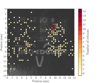
The figures 2 and 3 show the two sensibility maps with the number of crashes induced by the perturbations for every probe location over the SoC (for 27 tries per location). The area is divided in a 40 per 40 grid with a step of 350µm. This allows us to cover the whole package of the SoC. The first conclusion is that the sensibility of the component under EMFI depends on what is running on it. The setup running with Linux has a wider sensitive area than the bare metal one. However, the sensitive area of the bare metal setup is included in the Linux one. This suggests that the two setups behave similarly under the perturbations on this area. Since the Linux system embeds a far more complex piece of software than the bare metal one, with more enabled interfaces, it may explain that the Linux setup has a wider sensitive area.
3.2
Faults on bare metal versus faults on Linux
The sensitive areas are not the only differences of behaviour between the two setups. Another difference is the impacts of the perturbations. In other words, the faults obtained are different on the bare metal setup and the Linux setup. More precisely, the observable effect of a fault as seen by the same application is different whether it runs on a bare metal setup or on a Linux setup.
Evaluating the fault model on the Linux setup is a complex analysis.With an OS, faults are observable at the instruction level. This means the effect induced by the perturbation is equivalent to a fault modifying one or several instructions of the executed program.
On the bare metal setup, there are no observable faults at the instruction level but instead at the micro-architectural level, as shown in the next sections. The effect of the fault is equivalent to modifying the behaviour (signals or con-figuration for instance) of subsystems like buses, MMU, memory, caches, etc.
This difference suggests that the usage of an OS leads to a specific per-turbation behaviour. In this specific case, the fault model induced by the OS
3Raspbian Lite released on Wednesday 18th April, 2018 available here: https:// downloads.raspberrypi.org/raspbian_lite/archive/2018-06-29-03:25/
0 1 2 3 4 5 6 7 8 9 10 11 12 13 14 Position (mm) 0 1 2 3 4 5 6 7 8 9 10 11 12 13 14 P osition (mm) 0 1 2 3 4 5 6 7 8 9 10 11 12 13 14 Num b er of reb oots
Figure 2: Bare metal sensitivity map
0 1 2 3 4 5 6 7 8 9 10 11 12 13 14 Position (mm) 0 1 2 3 4 5 6 7 8 9 10 11 12 13 14 P osition (mm) 0 1 2 3 4 5 6 7 8 9 10 11 12 13 14 Num b er of reb oots
(instruction modification) is easier to exploit than the fault model on bare metal setup: the OS weakens the security of the system against fault injection attacks. In this work, we will focus on the fault model on the bare metal setup. We will show how to analyse and reconstruct the effect of a perturbation on the micro-architectural elements of a processor.
However, we can suppose that the micro-architectural fault effect on the bare metal setup explains the observed effect at the instruction level on the Linux one.
4
Fault on the instruction cache
In this experiment, we achieve a fault in the L1 instruction cache (L1I).
4.1
On the impossibility to fault the instruction execution
flow
Before reporting our positive results, we must report a negative one. Con-trary qto previous works on microcontrollers (where e.g. instructions are re-placed with a NOP instruction), we are not able to prevent or modify directly the execution of an instruction. In other words, in Listing 1, without the invalidate icache() no faults are observed. Even if we cannot be sure that no set of experimental parameters would achieve such a fault, we thoroughly explored the parameters without success.
As we will see in this section and the following, all faults affect memory subsystems. Probably because the buses involved in the memory transfers are easily coupled with our EM probe.
4.2
The target
The application targeted during this experiment is two nested loops shown on Listing 1, executed after the L1I cache invalidation. No fault is obtained without the invalidation. It is compiled without optimizations (-O0) since we do not want the compiler to optimize our code.
Since the instruction cache is invalidated before the loop execution, the fol-lowing instructions have to be (re)loaded in cache before their execution. And it is this memory transfer that we will target with our fault injection. By execut-ing the same application with and without the cache invalidation and measurexecut-ing the duration of the high state of the trigger, we deduce that loading instructions in cache has an overhead of 2µs. Our bench has a latency of 700 ns, so we can still hit this memory transfer. To be able to observe the effect of a fault on the full timing range, a 2µs wait has been inserted between the trigger and the cache invalidation.
4.3
Forensic
The fault is detected when the output sent back to the host is not 2500 (the value of cnt at the end of the program if everything went well). When a fault is detected, we use the JTAG to reexecute our application (in Listing 1) by directly setting the PC value at the start of the loops. Then, we execute our program instruction by instruction while monitoring the expected side effects (we do not inject faults anymore). All instructions are correct except one, the counter incrementing instruction (the add instruction at address 0x48a08 on Listing 2).
Listing 2: Loop target application assembly with -O0
... 48a04: b94017a0 ldr w0, [x29,#20] 48a08: 11000400 add w0, w0, #0x1 48a0c: b90017a0 str w0, [x29,#20] 48a10: b9401ba0 ldr w0, [x29,#24] 48a14: 11000400 add w0, w0, #0x1 48a18: b9001ba0 str w0, [x29,#24] 48a1c: b9401ba0 ldr w0, [x29,#24] 48a20: 7100c41f cmp w0, #0x31
48a24: 54ffff0d b.le 48a04 <loop+0x48> ...
By monitoring the w0 register before and after the cnt increment instruc-tion, we observe that the value is kept unchanged: the increment is not executed. Since the fault is still present after the EM injection, we conclude that a wrong instruction value is memorized in L1I. We confirm this fault model by execut-ing a L1I cache invalidation instruction ic iallu (we set the PC value to the instruction location in memory). Reexecuting our application, the fault has disappeared.
We can infer that the injected fault has modified a value in the L1I cache, but it is impossible to read the new value. Since the fault happens during the cache filling, we can suppose that it is the memory transfer that has been faulted.
4.4
Exploits
This fault is one of the easiest to exploit since it is similar to the classical instruction skip model. Therefore, most exploits based on this classical model apply here. Since the faulted value is still present in the cache, it will stay faulted until the cache is invalidated: we can call this model “sticky instruction skip”. Bukasa et al. [BLLL18] demonstrate applications of this fault model: hijacking the control flow and initiating a return-oriented programing (ROP) attack among others.
0x00390000: 00000703 00000000 00010703 00000000 0x00390010: 00020703 00000000 00030703 00000000 0x00390020: 00040703 00000000 00050703 00000000 0x00390030: 00060703 00000000 00070703 00000000 0x00390040: 00080703 00000000 00090703 00000000
Figure 4: Memory dump excerpt for PTEs before fault.
5
Targeting the MMU
The MMU is a critical component of SoCs. It is in charge of the virtual memory mechanism. In this section, the fault changes the virtual to physical memory mapping, albeit in an uncontrolled manner. The targeted application is the same as in section 4, shown on Listing 1.
5.1
The configuration of a working MMU
To understand the effect of the fault, we begin to explore the state of a working application (without any fault). This state is a legitimate one.
5.1.1 Page tables
The page tables are used to memorize the mapping between virtual and physical memory. In our configuration, we have 3 page table directorys (PTDs) (mapping 512 MB chunks) and for each one, we have 8192 PTE pages of 64 kB. We show an excerpt of the correct PTEs on Figure 4.
In the page tables, the most and least significant bits are used for the page metadata (access rights, caches configuration, etc.).
5.1.2 TLB
TLBs (plural since there are several of them), are small buffers used to speed up virtual to physical memory translation. As in a cache memory, the last mappings are saved to be reused later without a full page tables walk by the MMU. In the targeted SoC, TLB hierarchy mirrors cache hierarchy: the TLB designates the unified Level2 buffer while micro-TLBs are dedicated to instructions or data in each core.
5.1.3 Operating system
In our bare metal application, all the pages are initialized in the page tables with an identity mapping (virtual and physical addresses are identical). In a system with an OS, pages are allocated on-the-fly. On the one hand, this simplifies the forensic analysis since we are sure that page tables are correct prior to the fault. On the other hand, interesting faults may be missed if the OS page allocation is disrupted.
VA -> PA 0x0 -> 0x0 0x80000 -> 0x80000 0x10000 -> 0x10000 0x90000 -> 0x90000 0x20000 -> 0x20000 0xa0000 -> 0xa0000 0x30000 -> 0x30000 0xb0000 -> 0xb0000 0x40000 -> 0x40000 0xc0000 -> 0xc0000 0x50000 -> 0x50000 0xd0000 -> 0xd0000 0x60000 -> 0x60000 0xe0000 -> 0xe0000 0x70000 -> 0x70000 0xf0000 -> 0xf0000
Figure 5: Correct identity mapping
VA -> PA 0x0 -> 0x0 0x80000 -> 0x0 0x10000 -> 0x10000 0x90000 -> 0x0 0x20000 -> 0x20000 0xa0000 -> 0x0 0x30000 -> 0x30000 0xb0000 -> 0x0 0x40000 -> 0x40000 0xc0000 -> 0x80000 0x50000 -> 0x50000 0xd0000 -> 0x90000 0x60000 -> 0x60000 0xe0000 -> 0xa0000 0x70000 -> 0x70000 0xf0000 -> 0xb0000
Figure 6: Mapping after fault
5.2
Forensic
To reconstruct the memory mapping, we use a pair of instruction computing the physical address (and the corresponding metadata) for a given virtual one. A script has been designed to extract the memory mapping. By using the JTAG, first the two instructions at s1e3r, x0; mrs x0, PAREL1 are written at a given address, then the x0 register is set to one virtual address, the two instructions are executed and finally the x0 register contains the corresponding physical address.
With this method, we compare the memory mappings with (Figure 6) and without (Figure 5) a fault.
Three different effects can be observed depending on the page:
• Pages are correct with an identity mapping up to 0x70000. Remarkably theses are all the pages used to map our application in memory. Therefore, an hypothesis is that the corresponding translations are present in caches and are not impacted by the fault.
• Pages are incorrectly mapped to 0x0. A read at 0x80000 reads with success physical memory at 0x0.
• Pages are shifted. A read at 0xc0000 reads physical memory at 0x800000. If we invalidate the TLB after a fault, nothing changes: the mapping stays modified. We conclude that the fault does not affect the cache mechanism of
0x00390000: 40020607 00000000 40030607 00000000 0x00390010: 40040607 00000000 40050607 00000000 0x00390020: 40060607 00000000 40070607 00000000 0x00390030: 40000000 8a210002 40000000 8a210002 0x00390040: 400a0607 00000000 400b0607 00000000
Figure 7: Memory dump excerpt for PTEs after a fault.
address translation (at least what can be invalidated by software) but directly the MMU.
To look for an explanation of the incorrect mapping, we can look for the impact on page tables on Figure 7.
The fault on the MMU has shifted the page tables in memory, and has inserted errors in it. Since the memory translation is still valid after the fault, and do not correspond to the shifted page tables, this shift is not the only source of incorrect translation. Either the page walk is done from physical addresses and/or some TLB are not properly invalidated when we try to.
5.3
Exploit
This fault shows that the cornerstone of the key security feature in any SoC, namely memory isolation, does not withstand fault injection. In [vdVFL+16b],
the authors use the rowhammer attack to fault a PTE. The faulted PTE accesses the kernel memory which allow the attacker to obtain a privilege escalation: by overwriting an userland PTE for accessing all the memory, by changing the user ID to root or by changing the entry point of an executable.
Additionally, this fault model is a threat to pointer authentication coun-termeasures, as proposed in the recent ARMv8.3 ISA. This pointer protection works by storing authentication metadata in the most significant bits (usually useless) of a pointer value. To use a pointer, the chip first validates the authen-tication metadata. In our case, the attacker does not need to alter the pointer value, it can alter where it physically points to, at a coarse (page) granularity.
6
Shifting data chunks in L2
Another interesting behaviour when faulting a modified version of the loop target, cf listing 3, was investigated with JTAG.
Listing 3: Targeted assembly
489bc: a9be7bfd stp x29, x30, [sp,#-32]! 489c0: 910003fd mov x29, sp 489c4: b9001fbf str wzr, [x29,#28] 489c8: b9001bbf str wzr, [x29,#24] 489cc: b90017bf str wzr, [x29,#20] 489d0: 900001a0 adrp x0, 7c000 <RT2+0xb0> 489d4: 912d2000 add x0, x0, #0xb48
489d8: d2802002 mov x2, #0x100 489dc: 52800001 mov w1, #0x0 489e0: 94000b28 bl 4b680 <memset> 489e4: 97fefe67 bl 8380 <fast_trig_up> 489e8: d2800040 mov x0, #0x2
489ec: 97feffe2 bl 8974 <wait_us>
489f0: 94008765 bl 6a784 <invalidate_icache> 489f4: 940087ad bl 6a8a8 <init_registers> 489f8: b9001fbf str wzr, [x29,#28] 489fc: 14000010 b 48a3c <loop+0x80> 48a00: b9001bbf str wzr, [x29,#24] 48a04: 14000008 b 48a24 <loop+0x68>
48a08: 940087c1 bl 6a90c <register_transfer> 48a0c: b94017a0 ldr w0, [x29,#20] 48a10: 11000400 add w0, w0, #0x1 48a14: b90017a0 str w0, [x29,#20] 48a18: b9401ba0 ldr w0, [x29,#24] 48a1c: 11000400 add w0, w0, #0x1 48a20: b9001ba0 str w0, [x29,#24] 48a24: b9401ba0 ldr w0, [x29,#24] 48a28: 7100c41f cmp w0, #0x31
48a2c: 54fffeed b.le 48a08 <loop+0x4c>
We observe that data are shifted in the L2 cache, as if addresses had been slightly modified in the memory transfer writing to L2.
6.1
Forensic
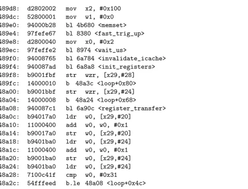
A quick step by step execution shows that we are trapped into an infinite loop. A JTAG memory dump at the instruction memory location shows modified instructions as seen on Figure 8, to be compared to the unfaulted dump on Figure 9.
With the same parameters, several similar faults have been obtained with two observed faulty memory dumps, here called F1 and F2. Similar because the same infinite loop is obtained (as shown in step by step execution), but the memory dumps obtained from JTAG are slightly different. We will show that the difference is due to discrepancies between caches for F2 and that invalidating L1I cache restore coherence with the F1 results.
0x000489d8: d2800040 97feffe2 00000002 00000008 0x000489e8: 00000002 00000008 910003fd b9001fbf
0x000489f8: b9001bbf b90017bf 11000400 b90017a0 0x00048a08: b9401ba0 11000400 b9001ba0 b9401ba0
0x00048a18: 7100c41f 54fffeed b9401fa0 11000400 0x00048a28: b9001fa0 b9401fa0 81040814 77777777
Figure 8: Memory dump showing the instructions in the infinite loop as seen by the JTAG for F1. The instructions in the infinite loop are underlined.
0x000489b8: d65f03c0 a9be7bfd 910003fd b9001fbf
0x000489c8: b9001bbf b90017bf 900001a0 912d2000 0x000489d8: d2802002 52800001 94000b28 97fefe67 0x000489e8: d2800040 97feffe2 94008765 940087ad 0x000489f8: b9001fbf 14000010 b9001bbf 14000008
0x00048a08: 940087c1 b94017a0 11000400 b90017a0 0x00048a18: b9401ba0 11000400 b9001ba0 b9401ba0
0x00048a28: 7100c41f 54fffeed b9401fa0 11000400
Figure 9: Memory dump showing correct (without fault) instructions for the same memory region.
The step by step execution is coherent with the instructions shown by the JTAG dump for F1 (registers are loaded, stored and incremented as specified by the instructions in this dump, not the correct ones). Since JTAG dump and instructions execution are coherent, it seems that the fault is present in L2 cache (unified view). The reconstructed instructions can be seen in listing 4.
Listing 4: Assembly reconstruction of the faulted instructions
489f8: b9001bbf str wzr, [x29,#24] 489fc: b90017bf str wzr, [x29,#20] 48a00: 11000400 add w0, w0, #0x1 48a04: b90017a0 str w0, [x29,#20] 48a08: b9401ba0 ldr w0, [x29,#24] 48a0c: 11000400 add w0, w0, #0x1 48a10: b9001ba0 str w0, [x29,#24] 48a14: b9401ba0 ldr w0, [x29,#24] 48a18: 7100c41f cmp w0, #0x31 48a1c: 54fffeed b.le 489f8
MMU After verification as in section 5, we observe that the MMU mapping is indeed modified but not for the memory region of interest. In particular, memory addresses from 0x0 to 0x7FFFF are still correctly mapping identically virtual and physical addresses. The fault on the MMU cannot therefore explain our observations.
L1 fault The L1I is of course modified by the fault since the behaviour of the application is modified. But the execution is coherent with the JTAG dump (showing the L1D cache) hinting that L2 is impacted too. As seen on figure 10, the dump after F2 shows different values in L1D memory with respect to F1 (for the first two instructions), but the execution trace is coherent with F1 JTAG dump (on figure 8), not with F2 JTAG dump (on figure 10).
As it turns out, 940087c1 encodes a branching instruction that is not fol-lowed in the step by step execution. In the case of F2, the JTAG dump does not reflect the values in the L1I cache. If we invalidate L1I cache, nothing change (either in the execution trace or in the JTAG dump). But if we invalidate to
0x000489f8: 940087c1 b94017a0 11000400 b90017a0 0x00048a08: b9401ba0 11000400 b9001ba0 b9401ba0
0x00048a18: 7100c41f 54fffeed b9401fa0 11000400 0x00048a28: b9001fa0 b9401fa0 7100c41f 54fffded
Figure 10: Memory dump showing the instructions in the infinite loop as seen by the JTAG for F2.
point of coherency at address 0x489f8, then the new JTAG dump becomes the same as for F1.
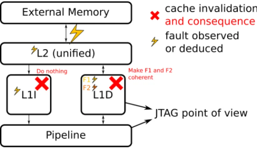
Hypotheses The effect of these faults seem to manifest in the L2 cache. We can observe that it consists in shifting groups of 4 instructions (128 bits or 16 B, under the cache line size of 64 B) at a nearby memory location. 128-bit is the size of the external memory bus connected to L2. A fault model could be that the address corresponding to a cache transfer toward L2 has been modified by a few bits.
Figure 11: Summary of our fault model for the faults observed in section 6.
The fault model is summarized on Figure 11. But our model has some limits: the presence of F2 means that, with one fault, values in L2 and in L1D are modified simultaneously in an uncoherent way. Is it due to the EM probe coupling with several buses or to a micro-architectural mechanism ?
6.2
Exploits
A fault in the L2 cache can impact either the instructions or the data giving more power to the attacker. Yet she does not control in what way the memory will be modified. Why these particular 16 bytes blocks have been shifted? Nevertheless, just corrupting data or instruction randomly is often enough to achieve the desired effect (as in the NOP fault model).
7
Countermeasures
The vulnerabilities described above can be summarized as integrity and au-thenticity problems: instructions (or data) are altered between their storage in memory and their reuse. If we consider that only a legitimate entity can write to memory, then integrity is the only problem. In the other case, we must also ensure the write authenticity.
7.1
Ensuring integrity
Ensuring the integrity of signals in a chip is a well known problem that had to be solved to allow the use of chips in harsh environments: space or nuclear reactors for example. Yet one must account for a different threat model: when designing for security, the fault value must be considered intentional, not drawn from a uniformly random distribution.
To ensure integrity, designers use redundancy. We can duplicate the core, executing exactly the same things on both cores and verifying that results are identical. Redundancy can also be achieved using error detection codes. Of course, redundancy has an overhead but this is the cost of guaranteeing the integrity.
When dealing with the threat of physical attacks, ensuring integrity is often not enough. If we consider that the attacker can modify memory, she could bypass the error detection code or write the same error value in the duplicated memories. In this case, we must ensure the data authenticity. With cryptog-raphy, authenticity can be guaranteed by relying on message authentication codes (MACs). We can imagine a strategy based on this principle to be able, in hardware, to detect changes in data or instructions.
7.2
MAC Generation
A solution, to ensure authenticity has been proposed with SOFIA [dCGU+17].
For each data or instruction block (the block size has to be adapted to the micro-architecture), the objective is to calculate and associate a MAC to detect any alteration. In addition to the data itself, the MAC calculation must also be address dependent to detect shifts between an address and the corresponding data (as observed in the L2 cache in section 6). MACs must be generated at the right time: in the case of instructions, they can be computed at compile time. But for the data, it must be possible to do the generation at the pipeline output (during memory access).
7.3
MAC Verification
Depending on the energy consumption/performance trade-off, two implementa-tion strategies can then be considered on a system-wide basis to perform the MAC check.
• Just-in-time: To minimize the overall activity, this strategy consists in bringing the data and its MAC back to the CPU (or MMU) in a classical way. The verification would then be performed by the CPU just before data consumption. In case of mismatch, a request has to be made to the higher memory level (the L1 cache) to perform a verification on its own data version. If the new verification is successful, the data would be transmitted to the CPU and if not, a request to the next level (L2) has to be made. Thus, several checks are performed only when necessary, but the cost of a mismatch (that can be due to environmental radiations) is very high.
• Proactive: A second strategy can be used to reduce the time penalty in case of error. Integrity checks are automatically performed at each level of the memory hierarchy. Thus, errors can be detected early, before they reach the CPU. Each cache level can ensure independently that it has only valid data, but the energy consumption would be higher.
8
Conclusion
In this paper, we have demonstrated some vulnerabilities with respect to fault injection attacks specific to SoC. In particular, the memory hierarchy and the MMU can be altered which creates a mismatch between how the hardware be-have and what the software expect. Nowadays, the computing systems security is focused on the software side, there are no efficient countermeasure against hardware perturbations in modern SoC. Pointer authentication as proposed by the ARMv8.3 ISA, for example, does not resist the introduced fault model.
Exploitation depends heavily on the interaction between the hardware (the specific device) and the software (including application and OS). Therefore the cautious developer cannot predict where vulnerabilities will occurs and as a con-sequence cannot efficiently protect its application. Today, such attacks using EMFI are still quite hard to realize: they require expensive apparatus, human resources to do the experiments, etc. But they are within reach of small orga-nizations and we can expect that the difficulty and cost of these attacks will be lower in the future.
Actions must be taken to ensure that computing systems handle sensitive information securely. The performances/energy consumption trade-off has been settled by implementing the two kinds of cores in the same SoC. In the same way, we need secure cores as well that compromise both on performances and energy consumption but can offer much stronger security guarantees.
References
[BDL97] Dan Boneh, Richard A. DeMillo, and Richard J. Lipton. On the importance of checking cryptographic protocols for faults. In Walter Fumy, editor, Advances in Cryptology — EUROCRYPT
’97, pages 37–51, Berlin, Heidelberg, 1997. Springer Berlin Hei-delberg.
[BGV11] Josep Balasch, Benedikt Gierlichs, and Ingrid Verbauwhede. An in-depth and black-box characterization of the effects of clock glitches on 8-bit mcus. In 2011 Workshop on Fault Diagnosis and Tolerance in Cryptography, FDTC 2011, Tokyo, Japan, Septem-ber 29, 2011, pages 105–114, 2011.
[BLLL18] Sebanjila K. Bukasa, Ronan Lashermes, Jean-Louis Lanet, and Axel Leqay. Let’s shock our iot’s heart: Armv7-m under (fault) attacks. In Proceedings of the 13th International Conference on Availability, Reliability and Security, ARES 2018, pages 33:1– 33:6, New York, NY, USA, 2018. ACM.
[BS97] Eli Biham and Adi Shamir. Differential fault analysis of secret key cryptosystems. In Burton S. Kaliski, editor, Advances in Cryptology — CRYPTO ’97, pages 513–525, Berlin, Heidelberg, 1997. Springer Berlin Heidelberg.
[CH17] Ang Cui and Rick Housley. BADFET: Defeating Modern Secure Boot Using Second-Order Pulsed Electromagnetic Fault Injec-tion. In William Enck and Collin Mulliner, editors, 11th USENIX Workshop on Offensive Technologies, WOOT 2017, Vancouver, BC, Canada, August 14-15, 2017. USENIX Association, 2017. [dCGU+17] Ruan de Clercq, Johannes G¨otzfried, David Ubler, Pieter Maene,
and Ingrid Verbauwhede. Sofia: Software and control flow in-tegrity architecture. Computers & Security, 68:16 – 35, 2017. [Gir05] Christophe Giraud. Dfa on aes. In Hans Dobbertin, Vincent
Ri-jmen, and Aleksandra Sowa, editors, Advanced Encryption Stan-dard – AES, pages 27–41, Berlin, Heidelberg, 2005. Springer Berlin Heidelberg.
[KGG+18] Paul Kocher, Daniel Genkin, Daniel Gruss, Werner Haas, Mike Hamburg, Moritz Lipp, Stefan Mangard, Thomas Prescher, Michael Schwarz, and Yuval Yarom. Spectre attacks: Exploit-ing speculative execution. CoRR, abs/1801.01203, 2018.
[LSG+18] Moritz Lipp, Michael Schwarz, Daniel Gruss, Thomas Prescher,
Werner Haas, Stefan Mangard, Paul Kocher, Daniel Genkin, Yuval Yarom, and Mike Hamburg. Meltdown. CoRR, abs/1801.01207, 2018.
[MBB16] F. Maj´eric, E. Bourbao, and L. Bossuet. Electromagnetic se-curity tests for soc. In 2016 IEEE International Conference on Electronics, Circuits and Systems (ICECS), pages 265–268, Dec 2016.
[MDH+13] Nicolas Moro, Amine Dehbaoui, Karine Heydemann, Bruno Ro-bisson, and Emmanuelle Encrenaz. Electromagnetic fault injec-tion: Towards a fault model on a 32-bit microcontroller. In 2013 Workshop on Fault Diagnosis and Tolerance in Cryptography, Los Alamitos, CA, USA, August 20, 2013, pages 77–88, 2013. [OGM15] S´ebastien Ordas, Ludovic Guillaume-Sage, and Philippe
Mau-rine. EM injection: Fault model and locality. In 2015 Workshop on Fault Diagnosis and Tolerance in Cryptography, FDTC 2015, Saint Malo, France, September 13, 2015, pages 3–13, 2015. [PHM+19] Julien Proy, Karine Heydemann, Fabien Maj´eric, Alexandre
Berzati, and Albert Cohen. A first isa-level characterization of em pulse effects on superscalar microarchitectures — a secure software perspective. In ARES 2019, 2019.
[PQ03] Gilles Piret and Jean-Jacques Quisquater. A differential fault attack technique against spn structures, with application to the aes and khazad. In Colin D. Walter, C¸ etin K. Ko¸c, and Christof Paar, editors, Cryptographic Hardware and Embedded Systems - CHES 2003, pages 77–88, Berlin, Heidelberg, 2003. Springer Berlin Heidelberg.
[RNR+15] Lionel Rivi`ere, Zakaria Najm, Pablo Rauzy, Jean-Luc Danger,
Julien Bringer, and Laurent Sauvage. High precision fault in-jections on the instruction cache of armv7-m architectures. In IEEE International Symposium on Hardware Oriented Security and Trust, HOST 2015, Washington, DC, USA, 5-7 May, 2015, pages 62–67, 2015.
[TSS17] Adrian Tang, Simha Sethumadhavan, and Salvatore J. Stolfo. CLKSCREW: exposing the perils of security-oblivious energy management. In Engin Kirda and Thomas Ristenpart, editors, 26th USENIX Security Symposium, USENIX Security 2017, Van-couver, BC, Canada, August 16-18, 2017., pages 1057–1074. USENIX Association, 2017.
[TSW16] Niek Timmers, Albert Spruyt, and Marc Witteman. Controlling PC on ARM using fault injection. In 2016 Workshop on Fault Diagnosis and Tolerance in Cryptography, FDTC 2016, Santa Barbara, CA, USA, August 16, 2016, pages 25–35, 2016. [vdVFL+16a] Victor van der Veen, Yanick Fratantonio, Martina Lindorfer,
Daniel Gruss, Cl´ementine Maurice, Giovanni Vigna, Herbert Bos, Kaveh Razavi, and Cristiano Giuffrida. Drammer: Determinis-tic rowhammer attacks on mobile platforms. In Proceedings of the 2016 ACM SIGSAC Conference on Computer and Commu-nications Security, Vienna, Austria, October 24-28, 2016, pages 1675–1689, 2016.
[vdVFL+16b] Victor van der Veen, Yanick Fratantonio, Martina Lindorfer, Daniel Gruss, Cl´ementine Maurice, Giovanni Vigna, Herbert Bos, Kaveh Razavi, and Cristiano Giuffrida. Drammer: Determinis-tic rowhammer attacks on mobile platforms. In Proceedings of the 2016 ACM SIGSAC Conference on Computer and Commu-nications Security, Vienna, Austria, October 24-28, 2016, pages 1675–1689, 2016.