is an open access repository that collects the work of Arts et Métiers Institute of
Technology researchers and makes it freely available over the web where possible.
This is an author-deposited version published in:
https://sam.ensam.eu
Handle ID: .
http://hdl.handle.net/10985/7754
To cite this version :
Ludovic LAHOUSSE, Stéphane LELEU, Jean-Marie DAVID, Olivier GIBARU, Sébastien
DUCOURTIEUX - Z calibration of the LNE ultra precision coordinate measuring machine - In: 7th
euspen International Conference, Germany, 207-05 - Proceedings of the 7th euspen International
Conference - 2007
Any correspondence concerning this service should be sent to the repository
Administrator :
archiveouverte@ensam.eu
Z calibration of the LNE ultra precision coordinate
measuring machine
L. Lahousse1, S. Leleu2, J. David2, O Gibaru2, S. Ducourtieux1
1
LNE, Laboratoire National de Métrologie et d’Essais, France
2
L2MA-Ecole Nationale Supérieure d’Arts et Métiers, France Ludovic.Lahousse@lne.fr
Abstract
The Laboratoire National de Métrologie et d’Essais (LNE) has developed an innovative ultra precision coordinate measuring machine [1,2] traceable to the national length standard. This machine can be equipped with different kinds of sensors and is dedicated to the measurement with nanometer uncertainties of features, standards and in more general way three-dimensional objects. The measuring range is 300 mm x 300 mm x 50 µm. The objective in term of uncertainty is to reach 30 nm in X and Y directions for a 300 mm displacement and about few nanometers for the 50 µm vertical displacement. For the geometric calibration of this machine, dedicated procedures have been developed. The present paper will focus more specifically on the one used for the Z calibration.
1 Introduction
The machine displacements along the vertical direction are detected using four capacitive sensors integrated at each corner of the sample holder. These sensors target four flatness references linked to the reference space of the machine. Each flatness reference consists of a massive circular aluminum alloy plate to improve the shape stability. Due to the machine 300 mm displacements along X and Y direction, the capacitive sensors cover a large surface of the targeted reference flatness. In addition, the level of uncertainty targeted for the Z displacements is very low. These are the two reasons why we need to calibrate the flatness references. This calibration will be
Figure 1 : photograph of the machine
300 mm XY stage 4x4 capacitive sensor matrix and integrated inclination sensor flatness reference inclination sensor
surface plate
processed on the machine itself the flatness references mounted. At the moment, to develop and test the method, we have developed a dedicated bench (figure 1).
2 Equipment description
Figure 2 : developed bench
To calibrate the flatness references, we use a method based on propagation process and using sixteen capacitive sensors. These sensors are located according to a 4x4 matrix in order to generate measurement redundancy. The matrix is put on a surface plate and a 300 mm XY stage is used to scan the matrix under the reference flatness. At each point of the scan a measurement of the distance between the capacitive sensor supported by the matrix and the reference is done. One disadvantage of this method is that a calibration error in the relative position of the capacitive sensors introduces a flatness error with an ellipsoidal shape. To manage this error, we have equipped the capacitive sensor matrix and the reference flatness to calibrate with a dual axis inclination sensor (Leica - Nivel 20). The angle measured between the reference flatness and the sensor matrix is used to eliminate the ellipsoidal shaped error. The resolution of this inclination sensor is one micro-radian which is not sufficient to be comparable with the resolution of the capacitive sensors. Nevertheless, the repeatability of the inclination sensor is better than its resolution so it’s possible to increase the resolution making the sensor oscillate. To do that, we have introduced two piezoelectric actuators, one to rotate the capacitive sensor matrix in which the first inclination sensor is integrated and one another to make oscillate the reference on which the second sensor lies.
3 method presentation
We will present only the method applied to the measurement of straightness, the transition from the straightness to the flatness being only one generalization of this
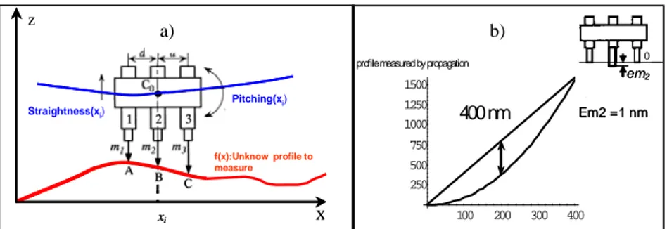
technique. The measurement by propagation consists in using a matrix which carries capacitive sensors and moves according to the profile to characterize (see Figure 3a).
Figure 3 : a) general diagram for straightness measurement using 3 capacitive sensors. b) Skew of rebuilding for a shifted sensor 2 of 1 nm
The position of the two first points is taken arbitrarily. It corresponds to the initial vertical position and inclination of the sensor matrix. The measurement of the third sensor gives the altitude of the 3rd point. After a translation d of the sensor matrix, the two first sensors make possible to readjust the position of the carriage sensor in straightness and pitching and the altitude of the 4th point is given by the 3rd sensor and so on. One of the difficulties of this method resides in the knowledge of the relative position of the sensors. Indeed, if sensor 2 is shifted of one nanometer compared to sensors 1 and 3, the simulation of the profile rebuilding by propagation shows a skew of 400 nm for a 400 millimeters length profile and a step d of 10 millimeters (see Figure 3b).
This result shows the extreme sensitivity of this parameter. The solutions suggested in the bibliography [LI96][GAO02] are based on a technique of reversal to determine this quantity. They are however difficult to realize. One second difficulty comes from the great sensitivity of the propagation method to the sensor local accuracy. Three original major evolutions were proposed to attain the project objectives. The first consists in integrating an electronic level to measure the angular movements of the sensor matrix. This additional information makes possible to know the relative position of the sensors in a sufficiently fine way. The second lies in the addition of sensors in order to introduce a redundancy into measurement which makes possible to reduce the result uncertainty and allows a self-checking of the measurement process. The third consists in micro-actuating the sensor matrix in
0 100 200 300 400 250 500 750 1000 1250 1500 Profilmesurépar propagation 400 nm profile measuredby propagation
0 100 200 300 400 250 500 750 1000 1250 1500 Profilmesurépar propagation 400 nm profile measuredby propagation
X xi f (x) : profil inconnu à mesurer Tangage (xi)
Rectitude (xi) Straightness(xi)
Pitching(xi) f(x):Unknow profile to measure X xi f (x) : profil inconnu à mesurer Tangage (xi)
Rectitude (xi) Straightness(xi)
Pitching(xi) f(x):Unknow profile to measure z 0 0 em2 Em2 =1 nm 0 0 em2 Em2 =1 nm a) b)
order to improve the inclination sensor resolution. Another advantage of the micro-actuation is to use the capacitive sensors on a more significant range and thus reduce sensitivity to sensor local errors accuracy.
4 First results
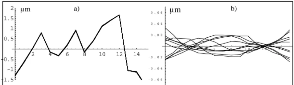
The measurements presented below were carried out on the bench in a air-conditioned environment but without thermal protections. The results obtained are very encouraging. With unfavorable measurement conditions, we get on these first measurements a standard deviation of a twentieth of nanometers.
Figure 4: a) straightness of one profile measured ten times, b) difference in each profile compared to the profile average
5 Conclusion
The first measurements of straightness are encouraging. Soon, more consequent measurements series will be carried out, the bench will be equipped with thermal protection guaranteeing a better thermal stability and flatness measurements will begin. We are now thinking of another method of measurement allowing us to validate our algorithm by comparison.
References :
[LI96] Li CJ, Li S, Yu J. "High-resolution error separation technique for in-situ straightness measurement of machine tools and workpieces." Mechatronics1996;6(3):337-347
[GAO02] Gao W, Yokoyama J, Hidetoshi K, Satoshi K. "Precision measurement of cylinder straightness using a scanning multi-probe system." Precision Eng. 2002; 26 :279-288 2 4 6 8 1 0 1 2 1 4 - 0 . 0 6 - 0 . 0 4 - 0 . 0 2 0 . 0 2 0 . 0 4 0 . 0 6 µm 2 4 6 8 10 12 14 -1.5 -1 -0.5 0.5 1 1.5 2 µm a) b)