UNIVERSITÉ DE MONTRÉAL
PRODUCTION OF CHITOSAN-BASED NON-WOVEN MEMBRANES USING
THE ELECTROSPINNING PROCESS
MEHDI PAKRAVAN LONBANI DÉPARTEMENT DE GÉNIE CHIMIQUE ÉCOLE POLYTECHNIQUE DE MONTRÉAL
THÈSE PRÉSENTÉE EN VUE DE L’OBTENTION DU DIPLÔME DE PHILOSOPHIAE DOCTOR
(GÉNIE CHIMIQUE) JUILLET 2012
UNIVERSITÉ DE MONTRÉAL
ÉCOLE POLYTECHNIQUE DE MONTRÉAL
Cette thèse intitulée:
PRODUCTION OF CHITOSAN-BASED NON-WOVEN MEMBRANES USING THE ELECTROSPINNING PROCESS
présentée par: PAKRAVAN LONBANI, Mehdi
en vue de l’obtention du diplôme de: Philosophiae Doctor a été dûment acceptée par le jury d'examen constitué de:
M. DUBOIS Charles, Ph.D., président
Mme. HEUZEY Marie-Claude, Ph.D., membre et directrice de recherche M. AJJI Abdellah, Ph.D., membre et codirecteur de recherche
M. CARREAU Pierre, Ph.D., membre
DEDICATION
AKNOWLEDGEMENTS
I vividly remember the day I received the letter of PhD program scholarship from faculty of chemical engineering, Ecole Polytechnique de Montreal, and still recall all the mixed feelings; the joy of stretching out my wings and the sorrow of leaving loved ones behind.
Today I am all again filled with emotions; the excitement of accomplishment and the bliss of contentment. I am certainly blessed to be surrounded by mentors, supervisors, supporters, friends and family who enlightened my growth path and disclosed new horizons ahead. I am grateful and in depth with them all, specially:
Dr. Marie-Claude Heuzey, for supervising my PhD research program, believing in me,
supporting and challenging me; my sincere appreciation to you, your patience, enthusiasm toward scientific research and all the productive discussions.
Dr. Abdellah Ajji, my other supervisor for his insightful suggestions, guidance, constructive
remarks and sharing his invaluable experience in experimental research. Thank you.
Prof. Pierre J. Carreau, for all his comments and discussion on my work presented in routine
rheology meetings and Prof. Basil Favis for his inspiring polymer blend course and knowledge. My special gratitude to the staff and technicians of Ecole Polytechnique de Montreal, chemical engineering department, Industrial Material Institute (IMI), and FPInnovations, for their contribution to this work.
Ladies: Mélina Hamdine, Weawkamol Leelapornpisit, Claire Circlé and Sylvie St. Amoure Gentlemen: Robert Delisle, Daniel Dumas, Jacques Dufour, Alexis Laforges, and Vincent Darras
My heartfelt thanks to my close friends: Farhad, Amir Hossein, Abbas, Nima, Hesam, Marie, Afra, Shant, Fatemeh and Ahmad.
My beloved parents, Nayereh and Reza for their eternal caring open heart, open arms and their full presence regardless of distance.
Maryam, my love, wife, best friend, and encourager and our little son, Emaad who his charm made it possible throughout the tough times.
RÉSUMÉ
Le chitosane est un polymère naturel modifié produit à partir de la chitine, un des matériaux organiques le plus abondant dans la nature. Les applications biomédicales du chitosane tels que les échafaudages en génie tissulaire et les pansements d’aide à la cicatrisation ont beaucoup attiré l'attention ces derniers temps en raison de l’origine naturelle du chitosane et ses propriétés exceptionnelles telles que la biodégradabilité, la biocompatibilité et la non-toxicité. Les mats nanoporeuses de chitosane présentent les propriétés physico-chimiques spécifiques du matériau de base et bénéficient aussi des caractéristiques physiques de ces membranes en raison de leur morphologie et de grande surface spécifique. Réaliser ces structures en satisfaisant à des exigences essentielles telles que la flexibilité et une porosité élevée reste toujours difficile. L’électrofilage est une nouvelle technique développée récemment pour générer des fibres de polymères de taille nanométrique. Grâce à cette technique, des mats non-tissés poreux ayant une surface nettement élevée par rapport à la masse (généralement de 40 à 100 m2/g) sont produits. Toutefois, la capacité d’électrofiler le chitosane est limitée principalement en raison de sa nature polycationique et de sa structure chimique rigide. Plusieurs démarches entreprises pour préparer des nanofibres électrofilées de chitosane n'ont pas réussi car les membranes préparées sont facilement dissoutes dans des solvants aqueux neutres et faibles acide, les propriétés des nanofibres sont affaiblies à cause de l’importante quantité de l’agent de co-électrofilage ou parce que les procédés utilisant des solvants nocifs dont les résidus peuvent se retrouver dans le produit final sont des préoccupations importantes.
Le but de ce travail est de fabriquer des membranes microporeuses non-tissées à base de nanofibres de chitosane pour des pansements de cicatrisation et pour filtrer les ions métalliques lourds de l'eau potable. Par conséquent, la préparation de nanofibres à haute teneur en chitosane à partir de solutions aqueuses est un objectif à atteindre pour ces applications. Dans cette thèse, deux approches ont été utilisées pour préparer les nanofibres à base de chitosane: l’électrofilage d’un mélange d’une solution de chitosane avec une solution facilement électrofilable telle qu’une solution aqueuse d’oxyde de polyéthylène (PEO) – et l’électrofilage co-axial des deux solutions. Par conséquent, l’interprétation du comportement des phases et la miscibilité des solutions aqueuses acides de chitosane et de PEO et leurs mélanges est d’une importance cruciale,
puisqu’une séparation de phases ayant lieu pendant le procédé d’électrofilage change grandement la morphologie et les propriétés physico-mécaniques des produits finaux.
Premièrement, l’approche rhéologique a été utilisée sur une solution aqueuse de PEO bien caractérisée pour élaborer le protocole expérimental. En comparant les points critiques observés avec ceux obtenus par d'autres techniques expérimentales, nous avons montré que des mesures rhéologiques peuvent détecter de manière sensible les stades précoces de séparation de phases. Par conséquent, le procédé a été appliqué à des solutions de PEO, de chitosane ou du mélange des deux à différents ratios, dilués dans une solution d’acide acétique à 50% en masse. Ces solutions ont montré une température critique de solubilité inférieure (LCST) sur le diagramme de phase, qui est attribuée à l'existence de liaisons hydrogène entre les groupes actifs du chitosane, la chaîne principale du PEO et le solvant. Les températures de séparation de phase critiques des points binodaux et spinodaux ont été estimées à partir d’expériences isochrones en balayage de température. Les températures binodales obtenues confirment que les solutions de chitosane / PEO sont miscibles et stables à des températures modérées et que la séparation de phases a lieu à des températures plus élevées de 60 – 75 °C.
Alors, nous voulions comprendre de manière approfondie les propriétés de la solution chitosane / PEO qui permet d’obtenir un électrofilage réussi, c’est à dire continu et stable, et qui produit des nanofibres sans défaut et uniformes, des fibres sans relief ou non-perlées. Les effets de la composition du mélange et de la concentration en acide acétique sur les propriétés telles que la tension de surface et la conductivité, sur la possibilité d’électrofiler ces solutions ont été étudiés. Un chitosane fortement désacétylé (DDA = 97,5%) dans une solution d’acide acétique à 50% a été utilisé, c’est le degré le plus élevé de désacétylation du chitosane pour lequel il a été signalé que la préparation de nanofibres de chitosane était possible. Les caractéristiques rhéologiques de la solution de chitosane et de PEO, étant des paramètres importants du procédé d’électrofilage, ont été examinées et leurs relations avec la possibilité d’électrofiler ou non sont été évaluées. Comme nous avons montré que les solutions chitosane / PEO sont miscibles et stables à des températures modérées, un dispositif modifié pour électrofiler à des températures modérées (25-70 °C) a été conçu, permettant d’atteindre une quantité maximale de 90% en masse de chitosane dans des nanofibres non-perlées de chitosane / PEO ayant des diamètres de 60-80 nm de diamètre. Il a également été constaté que l’augmentation du rapport chitosane /
PEO de 50/50 à 90/10 a conduit à une réduction remarquable du diamètre des nanofibres de 123 à 63 nm à température ambiante.
En outre, nous avons constaté que des températures de procédé modérées (40-70 °C) aident à stabiliser le processus électrofilage de ces solutions et à produire des nanofibres non-perlées. Cependant, à des températures plus élevées (70-80 °C), le jet électrofilé est devenu instable et des fibres avec une morphologie perlée ont été obtenues. Ce phénomène a lieu dans une même gamme de températures que celle de la séparation de phases, déterminée précédemment par des études rhéologiques. Donc, la séparation de phases des solutions induite par la température est considérée comme à l’origine de cette observation. D'autre part, une étude par spectroscopie infra rouge à transformée de Fourier (FTIR) sur des films obtenu par évaporation du solvant et des nanofibres du mélange chitosane / PEO obtenues à la température ambiante a montré la présence d'interactions par liaison hydrogène entre le chitosane et le PEO. Ceci pourrait être une autre indication de la miscibilité entre ces deux polymères en solution à des températures modérées. Enfin, afin d’éliminer l’étape de mélange, et pour réduire la quantité de chitosane utilisé et positionner le chitosane sur la surface extérieure des nanofibres en vue des applications visées, la technique d’électrofilage coaxial a été utilisée. En utilisant le procédé en une étape d’électrofilage coaxial, des nanofibres avec une structure cœur-enveloppe de PEO / chitosane ont pour la première fois été produites à partir de solutions aqueuses, le chitosane étant l’enveloppe (couche extérieure) et le PEO le cœur (couche intérieure). Des nanofibres uniformes et sans défauts de 100-190 nm de diamètre ont été produites. La nanostructure cœur-enveloppe et la présence de chitosane à la surface ont été confirmées par des images TEM obtenues avant et après le lavage à l’eau du PEO contenu. La présence du chitosane à la surface des nanofibres composites a aussi été confirmée par des analyses XPS. L’analyse de la composition, de manière générale ou locale, a été effectuée par thermogravimétrie (TGA) et par FTIR, respectivement, pour examiner l’homogénéité des nanofibres. De plus, il a été montré que les nanofibres de chitosane creuses ont pu être obtenues par l’extraction du PEO dans les nanofibres coaxiales de PEO / chitosane, ce qui pourrait être d’un grand intérêt dans des applications comme la purification du sang en hémodialyse.
ABSTRACT
Chitosan is a modified natural polymer mainly produced from chitin, one of the most abundant organic materials in the world. Highly porous chitosan mats present the specific physicochemical properties of the base material and also benefit from the physical characteristics of nanoporous membranes. Electrospinning is a novel technique developed long time ago and revisited recently that can generate polymeric fibers with nanometric size.
The ultimate purpose of this work is to fabricate microporous non-woven chitosan membranes for wound healing dressings and heavy metal ion removal from drinking water. In this dissertation, two approaches have been utilized to prepare chitosan-based nanofibers; blending and co-axial electrospinning of chitosan solution with a readily electrospinnable solution, i.e. an aqueous solution of polyethylene oxide (PEO).
Consequently, understanding the phase behavior and miscibility of aqueous acidic solutions of chitosan and PEO and their blends is of crucial importance, as any phase separation occurring during the electrospinning process greatly changes the morphology and physico-mechanical properties of the final products.
First we employed the rheological approach on a well-known aqueous PEO solution to develop the experimental protocol. By comparing these critical points with that obtained from other experimental techniques, we showed that rheological measurements can sensitively detect early stages of phase separation. Subsequently the method was applied to 50 wt% aqueous acetic acid solutions of PEO, chitosan and their blends at different ratios. These solutions showed a lower critical solution temperature (LCST) phase diagram that is attributed to the existence of hydrogen bonds between active groups on chitosan and PEO backbone and the solvent. Critical decomposition temperatures for binodal and spinodal points were estimated from isochronal temperature sweep experiments. The obtained binodal temperatures confirmed that chitosan/PEO solutions are miscible and stable at moderate temperatures and phase separate at higher temperatures of 60-75 °C.
Then, we intended to obtain a thorough understanding of chitosan/PEO solution properties that lead to a successful electrospinning process, i.e. continuous and stable, and which produces defect free uniform beadless nanofibers. The effect of blend composition and acetic acid
concentration on properties such as surface tension and conductivity and, ultimately, on electrospinnability were investigated. A highly deacetylated chitosan (DDA=97.5 %) in 50% acetic acid was used, which is the maximum deacetylated chitosan grade that has been reported for the preparation of electrospun chitosan-based nanofibers. The rheological characteristics of the chitosan/PEO solutions as a controlling parameter in the electrospinning process were examined and their relationships to electrospinnability presented. As we showed that chitosan/PEO solutions are miscible and stable at moderate temperatures, a modified electrospinning set up to electrospin at temperatures of 25-70 °C was designed to achieve content as high as 90 wt% of chitosan in beadless chitosan/PEO nanofibers of 60-80 nm in diameter. It was also found that increasing chitosan/PEO ratio from 50/50 to 90/10 led to a remarkable diameter reduction from 123 to 63 nm at room temperature.
Additionally, we found that moderate process temperatures help to stabilize the electrospinning process of these solutions and produce beadless nanofibers. However, at higher temperatures, the electrospun jet became unstable and beaded fiber morphology was obtained. This phenomena occurs closely at the temperature range of phase separation, previously determined by rheology studies. Therefore, temperature-induced phase separation of these solutions is considered as the reason for that observation. On the other hand, an FTIR study at room temperature on cast films and nanofibers of chitosan/PEO blends at room temperature showed the presence of hydrogen bonding interactions between chitosan and PEO that could be an another indication of miscibility between these two polymers in solution at moderate temperatures.
Finally, in order to remove the blending step, reducing the amount of chitosan used and also to put chitosan right on the outer surface of the nanofibers for further related applications, a co-axial electrospinning technique was employed. By using a one-step co-axial electrospinning process, for the first time core-shell structured PEO-chitosan nanofibers from aqueous solutions were produced in which chitosan is located at the shell (outer layer) and PEO at the core (inner layer). Uniform sized defect-free nanofibers of 100-190 nm diameter were produced. The core-shell nanostructure and existence of chitosan on the shell layer were confirmed by TEM images obtained before and after washing the PEO content with water. The presence of chitosan on the surface of the composite nanofibers was further supported by XPS studies. Bulk and local compositional analysis is performed by thermal gravimetry (TGA) and Fourier transform infra-red spectroscopy (FTIR) techniques, respectively, to examine the homogeneity of the nanofibers.
Additionally, it was shown that hollow chitosan nanofibers could be obtained by PEO washing of the co-axial PEO/chitosan nanofibers, which could also be of great interest in applications such as blood purification in hemodialysis.
TABLE OF CONTENTS
DEDICATION ... III AKNOWLEDGEMENTS ... IV RÉSUMÉ ... V ABSTRACT ... VIII TABLE OF CONTENTS ... XI LIST OF TABLES ... XVI TABLE OF FIGURES ... XVIICHAPITRE 1 ... 1 INTRODUCTION ... 1 CHAPITRE 2 ... 4 LITERATURE REVIEW ... 4 2.1 Chitosan ... 4 2.1.1 Chitosan solubility ... 6 2.1.2 Chitosan applications ... 6 2.2 Nanofibers technology ... 8 2.2.1 Nanotechnology ... 8 2.2.2 Electrospinning technique ... 9
2.2.3 Applications of polymeric nanofibers ... 16
2.3 Nanofibrous chitosan membrane ... 17
2.3.1 Electrospinning of chitosan ... 18
2.3.2 Applications of electrospun chitosan nanofibers ... 20
2.4 Phase behavior of polymer solutions ... 20
2.6 Objectives ... 22
CHAPITRE 3 ... 24
SUMMARY OF ARTICLES ... 24
CHAPITRE 4 ... 26
DETERMINATION OF PHASE BEHAVIOUR OF POLY (ETHYLENE OXIDE) AND CHITOSAN SOLUTION BLENDS USING RHEOMETRY ... 26
4.1 Abstract ... 26
4.2 Introduction ... 27
4.3 Theoretical background ... 30
4.3.1 Scaling analysis of dynamic rheological properties near phase separation ... 30
4.3.2 Evaluation of Flory-Huggins interaction parameter for polymer solutions from their critical temperature and concentration data ... 34
4.4 Experimental section ... 36
4.4.1 Materials ... 36
4.4.2 Solutions preparation ... 36
4.4.3 Rheological measurements ... 37
4.5 Results and discussion ... 38
4.5.1 Determination of solution critical points by oscillatory shear measurements ... 38
4.5.2 Isothermal steady shear viscosity results ... 52
4.5.3 Flory-Huggins interaction parameter from rheological data ... 54
4.6 Conclusions ... 56
4.7 Acknowledgements ... 57
4.8 References ... 57
CHAPITRE 5 ... 60
5.1 Abstract ... 60 5.2 Introduction ... 61 5.3 Experimental ... 64 5.3.1 Materials ... 64 5.3.2 Chitosan characterization ... 64 5.3.3 Solutions preparation ... 65 5.3.4 Electrospinning ... 65 5.3.5 Film preparation ... 66 5.3.6 Rheological measurements ... 67
5.3.7 Fiber diameter characterization ... 67
5.3.8 Surface tension ... 68
5.3.9 Electrical conductivity ... 68
5.3.10 FTIR spectroscopy ... 68
5.4 Results and discussion ... 68
5.4.1 Material characterization ... 68
5.4.2 Solution characterization ... 69
5.4.3 FTIR spectra ... 74
5.4.4 Morphology of electrospun nanofibers and concentration regimes ... 77
5.4.5 Moderate temperature electrospinning ... 81
5.5 Conclusion ... 86
5.6 Acknowledgements ... 87
5.7 References ... 87
CHAPITRE 6 ... 91
CORE-SHELL STRUCTURED PEO-CHITOSAN NANOFIBERS BY COAXIAL ELECTROSPINNING ... 91
6.1 Abstract ... 91 6.2 Introduction ... 92 6.3 Experimental section ... 94 6.3.1 Materials ... 94 6.3.2 Master solutions ... 94 6.3.3 Electrospinning ... 95 6.3.4 PEO extraction ... 96 6.3.5 Film preparation ... 96 6.3.6 Characterization ... 96
6.4 Results and discussion ... 99
6.4.1 Rheological behaviour of solutions ... 99
6.4.2 Morphology and internal structure of the co-axial electrospun nanofibers ... 101
6.4.3 Structural features of the core-shell nanofibers; Compositional analysis ... 105
6.4.4 Crystalline structure of the nanofibers ... 108
6.4.5 Surface properties of core-shell nanofibers ... 111
6.5 Conclusions ... 113
6.6 Acknowledgements ... 114
6.7 Associated content ... 114
6.7.1 Supporting Information ... 114
6.7.2 Calculation of co-axial nanofibers density ... 115
6.8 References ... 115
CHAPITRE 7 ... 118
GENERAL DISCUSSION ... 118
CONCLUSIONS AND RECOMMENDATIONS... 121 8.1 Conclusions ... 121 8.2 Recommandations ... 122 APPENDICES ... 123 Appendix A ... 123 REFERENCES ... 124
LIST OF TABLES
Table 2.1: Main applications for chitosan (Rinaudo 2006)………..……….7 Table 2.2: Attractive properties of chitosan in relation to its use in biomedical applications
(Rinaudo 2006)………...…7 Table 4.1: A and B coefficients of Flory-Huggins interaction parameter, Eq. 12, and values of the
interaction parameter, χ, at given temperatures obtained by using different experimental methods……….. ... …………55 Table 6.1: Melting point and enthalpy of fusion of neat PEO powder and electrospun nanofibers
TABLE OF FIGURES
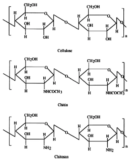
Figure 2-1: Chemical structure of cellulose, chitin and chitosan (Kumar 2000). ... 5 Table 2.1: Main applications for chitosan (Rinaudo 2006) ... 7 Table 2.2: Attractive properties of chitosan in relation to its use in biomedical applications
(Rinaudo 2006) ... 7 Figure 2-2: Schematic outline of a typical electrospinning set up. ... 10 Figure 2-3: SEM image of electrospun nanofibers and human hair (Greiner and Wendorff 2007). ... 10 Figure 2-4: Comparison of the diameter of electrospun nanofibers with nanoscale biological and
technological objects (Greiner and Wendorff 2007) ... 11 Figure 2-5: Evolution of Taylor Cone by increasing the electrical field (Reneker and Yarin 2008). ... 12 Figure 2-6: SEM image of beads produced by electrospinning of 1 wt% PEO (900 kDa) solution
in water, the horizontal edge of image is 20 μm long. (Fong et al. 1999). ... 12 Figure 2-7: SEM image of beaded fiber morphology obtained from electrospinning of 2.5 wt%
PEO (900 kDa) solution in water, the horizontal edge of image is 20 μm long (Fong et al. 1999). ... 13 Figure 2-8: SEM image of ribbon fiber morphology prepareded by electrospinning of 10% Poly
(etherimide) (Theron et al. 2004). ... 13 Figure 2-9: Photographs of a jet of PEO solution during electrospinning with two different
capture times: A) 1/250 s, B) 18 ns (Shin, Hohman et al. 2001). ... 15 Figure 2-10: The diversity of application areas proposed for electrospun nanofibers (Huang,
Zhang et al. 2003). ... 16 Figure 4-1: Isochronal dynamic temperature sweep of storage modulus ( ), loss modulus ( )
and tan δ for a solution of 6 wt % PEO in water. Measured at a fixed frequency of 1 rad/s, oscillatory stress of 2 Pa and heating rate of 0.5 °C/min. ... 39
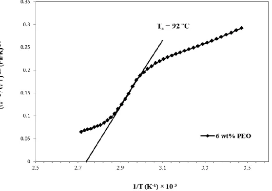
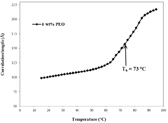
Figure 4-2: Estimation of spinodal temperature from the quantitative evaluation of the viscoelastic behaviour of a 6 wt% PEO in water near the phase boundary. The spinodal temperature is indicated in the figure by the intercept of the curve in the linear region. ... 41 Figure 4-3: Temperature dependence of the correlation length, for the 6 wt% PEO solution in
water obtained quantitatively from Eqn 11 (Section 5-2) and isochronous dynamic temperature sweep data (Fig. 5-1). ... 43 Figure 4-4: Frequency sweep plots of storage modulus, , and loss modulus, , for 4 wt%
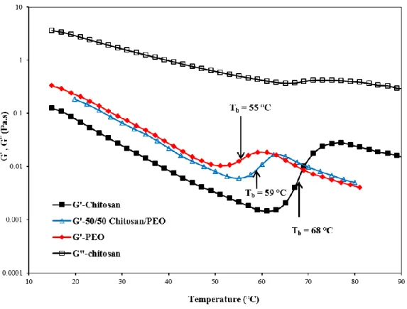
solutions of neat chitosan and PEO in 50 wt% aqueous acetic acid at 25 °C. ... 44 Figure 4-5: Isochronal dynamic temperature sweep of storage modulus ( ) and loss modulus
( ) for 4 wt % solutions of chitosan, PEO and their 50/50 blend in 50 wt% aqueous acetic acid solution. Measured at a fixed frequency of 1 rad/s, oscillatory stress of 2 Pa and heating rate of 0.5 °C/min. Vertical lines show the rheologically determined binodal temperatures at the inflection points of vs. temperature curves. ... 45 Figure 4-6: Isochronal dynamic temperature sweep of loss tangent angle (tan δ) for 4 wt% neat
chitosan, PEO and their 50/50 blend in 50 wt% aqueous acetic acid solution. Measured at a fixed frequency of 1 rad/s, oscillatory stress of 2 Pa and heating rate of 0.5 °C/min. Vertical lines show the rheologically determined binodal temperatures at the inflection points of tan δ vs. temperature curves. ... 47 Figure 4-7: Estimation of spinodal temperature from the quantitative evaluation of the
viscoelastic behaviour of neat chitosan, PEO and their 50/50 blend in 50 wt% aqueous acetic acid, near the phase boundary. The spinodal temperatures are indicated in the figure from the intercept of the curves in the linear region. ... 48 Figure 4-8: Binodal and spinodal phase separation temperatures of neat chitosan, neat PEO and
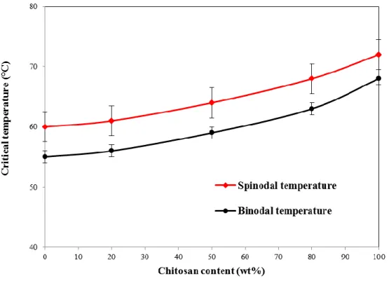
their blends at different ratios in 50 wt% aqueous acetic acid (Total polymer concentration is 4 wt% for all solutions). ... 49
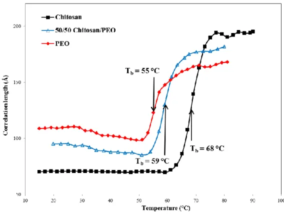
Figure 4-9: Temperature dependence of the correlation length, for neat chitosan, neat PEO and their 50/50 blend in 50 wt% aqueous acetic acid obtained quantitatively from the rheological measurements. ... 51 Figure 4-10: Plot of isothermal shear viscosity versus shear rate for A) 4 wt% neat chitosan
solution and B) its 50/50 blend with 4 wt% PEO over the temperature range covering homogeneous to the two-phase regimes of the solutions phase behaviours, all in 50 wt% aqueous acetic acid solvent. ... 53 Figure 5-1: A schematic outline of the electrospinning set-up. Inset shows the heated syringe
(inspired from Ref. [83]). ... 66 Figure 5-2: Chitosan 1H-NMR spectrum at 70 ºC. ... 69 Figure 5-3: Effect of acetic acid concentration and temperature on surface tension of aqueous
acetic acid solutions; 20 ºC: data from present study, 35 ºC & 50 ºC: data adapted from reference [64]. Surface tension of 4 wt% chitosan solution, PEO solution and their 50/50 blend overlie at 20 ºC, showing as a single point in the graph. The electrical conductivity of aqueous acetic acid solutions at 25 ºC is also shown (secondary y-axis). ... 71 Figure 5-4: Viscosity as a function of steady shear rate for chitosan, PEO and chitosan/PEO
solutions in various solvents (total polymer concentration of 4 wt%). ... 72 Figure 5-5: Effect of chitosan content on zero-shear viscosity of chitosan/PEO blends. A 4 wt%
chitosan solution is mixed with a 4 wt% PEO solution in a 50 wt% acetic acid solvent (total polymer concentration of 4 wt%). ... 73 Figure 5-6: Proposed hydrogen bonding interactions between chitosan and PEO molecules [63]. ... 74 Figure 5-7: Normalized transmission FTIR spectra recorded at room temperature in the ether (C-O-C) region for neat PEO film and as-spun chitosan/PEO nanofibers. ... 75 Figure 5-8: Normalized transmission FTIR spectra recorded at room temperature in the amine
(NH2) region for neat chitosan film and as-spun chitosan/PEO nanofibers. ... 76 Figure 5-9: Electrospun solutions: A) 4 wt% PEO in 50 wt% acetic acid, B) 4 wt% PEO in ... 76
water (tip to collector distance = 15 cm, flow rate = 0.5 mL/h, voltage = 15 kV), C) 4 wt% chitosan in 50 wt% acetic acid at 25 °C, (tip to collector distance = 15 cm, flow rate = 0.5 mL/h, voltage = 30 kV). Scale bars represent 10 µm. ... 76 Figure 5-10: Dependence of viscosity on shear rate for chitosan solutions at various
concentrations (50 wt% acetic acid at 25 °C). ... 78 Figure 5-11: Dependence of specific viscosity on concentration for chitosan dissolved in 50 wt%
acetic acid (T = 25 °C). ... 79 Figure 5-12: Effect of chitosan concentration on electrical conductivity of chitosan/PEO blends.
A 4 wt% chitosan solution is mixed with a 4 wt% PEO solution in a 50 wt% acetic acid solvent. ... 81 Figure 5-13: SEM micrographs of electrospun neat chitosan solutions at various temperatures (4
wt% chitosan in 50 wt% acetic acid), (tip to collector distance = 15 cm, flow rate = 0.5 mL/h, voltage = 30 kV). Scale bars represent 10 µm. ... 82 Figure 5-14: Effect of temperature on zero shear viscosity of 4 wt% neat chitosan and its 50/50
blend with 4 wt% PEO, all in 50 wt% acetic acid. ... 83 Figure 5-15: Effect of blend ratio (chitosan/PEO) and temperature on electrospun nanofibers
(blends of 4 wt% chitosan and 4 wt% PEO in 50% acetic acid); (tip to collector distance = 15 cm, flow rate = 0.5 mL/h, voltage = 30 kV). Scale bars represent 10 µm. ... 85 Figure 5-16: Effect of blend ratio (chitosan/PEO) and spinning temperature on fiber diameter,
total polymer concentration = 4 wt% in 50 wt% acetic acid, (tip to collector distance = 15 cm, flow rate = 0.5 ml/h, voltage = 30 kV). ... 86 Figure 6-1: Schematic representation of the co-axial electrospinning set-up. ... 96 Figure 6-2: Dependence of viscosity on shear rate for PEO solutions (in water and 50 wt% acetic
acid) and chitosan in 50 wt% acetic acid (data collected at 25 °C). ... 100 Figure 6-3: SEM micrograph and diameter histogram of co-axial electrospun nanofibers of
PEO/chitosan; scale bars represent 10 µm. A) 4 wt% PEO, B) 3 wt% PEO and C) 2 wt% PEO (flow rate 0.5 ml/h, needle to collector distance = 15 cm, voltage = 15 kV). ... 103
Figure 6-4: TEM micrographs of core-shell structured PEO-chitosan bi-component electrospun nanofibers, showing segments of the nanofibers with sharp boundaries; A) Concentric and B) Eccentric core and shell structures (Flow rate = 0.5 ml/h, needle to collector distance = 15 cm, voltage = 20 kV). ... 104 Figure 6-5: TEM micrograph of a hollow chitosan nanofiber obtained after water extraction of
the PEO core (Flow rate = 0.5 ml/h, needle to collector distance = 15 cm, voltage = 20 kV). ... 105 Figure 6-6: TGA curves of as-spun and PEO extracted co-axial electrospun PEO/chitosan mats
compared with neat chitosan and PEO powder A) raw TGA curves, and B) first-order derivative of TGA curves. ... 107 Figure 6-7: ATR-FTIR spectra of neat chitosan and PEO powder, and co-axial electrospun
PEO/chitosan nanofibers: as-spun and after extracting PEO by water. ... 108 Table 6.1: Melting point and enthalpy of fusion of neat PEO powder and electrospun nanofibers ... 109 Figure 6-8: DSC thermograms of neat chitosan and PEO powder, as-spun and washed co-axial
electrospun PEO/chitosan nanofibers, and 50/50 blend chitosan/PEO nanofibers. ... 109 Figure 6-9: XRD diffraction pattern of neat chitosan and PEO powder, co-axial electrospun PEO-chitosan nanofibers: as-spun and after extracting the PEO by water, and blended chitosan/PEO nanofibers (80/20 and 50/50 chitosan/PEO blend ratios). ... 111 Figure 6-10: Surface nitrogen composition of the blended chitosan/PEO electrospun nanofibers
and their cast films. The point represents the co-axial PEO/chitosan electrospun mats. ... 112 Figure 6-11: SEM image of PEO extracted co-axial PEO/chitosan nanofibrous mat ... 114
CHAPITRE 1
INTRODUCTION
Nanofibrous materials in the form of flat sheet membranes or three dimensional structures provide new solutions and vast opportunities to significantly improve current technologies and to create high value-added products and associated business development. Applications for nanofibers (defined as having diameter less than 0.5 μm) include tissue scaffolds, protective clothing, nanocatalysis, water and air filtration, nanosensors, separation membranes and health care products. Although there are other methods for fabricating nanofibers, none of them can be compared to electrospinning in terms of versatility, ease of fiber production and flexibility. Electrospinning is a novel and simple technique to generate polymeric fibers with nanometric size. Using this technique, non-woven porous mats with distinctly high surface area to mass ratio (typically 40-100 m2/g) are produced. The electrospinning technique is generally used to fabricate thin planar flat sheet mats with thickness of 50 to 200 μm. In this process a charged polymer solution flows out of a syringe/needle set up and accelerates toward a collector, mounted at a fixed distance from the needle. Then an electrostatically driven jet of polymer solution forms, elongates and whips until it is deposited on the collector, resulting in formation of non-woven random nanofibers. The prepared non-woven electrospun membranes exhibit remarkable characteristics such as distinctly high specific surface area, high porosity, small pores size and interconnected pore structure. Recent achievements in development of industrial scale electrospinning equipments have opened up the way to fabricate electrospun nanofibers for several applications. Therefore, nowadays research on electrospun nanofibers is not restricted only to academic research labs, but also different companies that are involved in the production of nanofibrous products for superior performance.
As for material selection in several biomedical applications, chitosan is among the most interesting due to its natural origin, non-toxicity, biocompatibility and biodegradability characteristics. Several methods such as phase inversion, phase separation and selective extraction have been used to produce porous chitosan morphologies. Lack of control over porosity and pore size dimensions and extracted phase and solvent residues in the final prepared structures are some negative aspects of these conventional methods. Therefore, microporous
chitosan structures obtained from the electrospinning process have gained much prominence recently. Highly porous electrospun chitosan-based mats present the specific physicochemical properties of the base material and benefit from the physical characteristics of nanoporous membranes because of their morphologies and large specific area. These materials show promising results in several applications such as wound healing dressings, anti-bacterial packaging films, drug delivery systems, scaffolds for tissue engineering and membranes for heavy metal ion absorption.
Chitosan is a modified natural polymer mainly produced from chitin, one of the most abundant organic materials in the world. Existence of –NH2 groups on the chitosan backbone provides
several unique properties such as solubility in acidic aqueous solvents, antifungal and antimicrobial properties and ability to chelate with heavy metal ions. However, chitosan is a challenging polymer to electrospin mainly due to its polycationic and rigid chemical structure in solution, and specific inter and intra- molecular interactions. The repulsive forces, arising from the protonation of –NH2 groups, could also restrict the formation of sufficient chain
entanglements needed for a successful electrospinning process.
Fabrication of chitosan-based electrospun nanofibers is a crucial step in order to produce the required structures for the above mentioned applications of interest. In this thesis, we aim to develop electrospun chitosan-based nanofibers with maximum chitosan content in stable electrospinning conditions, which can be used in various applications of interest, for example wound healing dressings and membranes for heavy metal ion removal from drinking water. To achieve that goal, the first part of this thesis is dedicated to provide a clear understanding about miscibility range and phase separation behaviour of chitosan, PEO and their blend solutions for further electrospinning process. To do so, rheological measurements are employed. Subsequently, electropsinnability of chitosan solutions in the presence of polyethylene oxide (PEO) as a co-spinning material was studied by performing a systematic study to obtain comprehensive knowledge about chitosan/PEO solution properties leading to a successful electrospinning process.
Finally, a one-step co-axial electrospinning set up is used to prepare a novel core/shell structured PEO/chitosan nanofibers with chitosan located on the outer layer.
This dissertation is based on three articles that have been published or submitted to scientific journals and comprised the following sections:
Chapter 2 provides a critical literature review considering the related issues and followed by the originality and main objectives of this dissertation.
The summary and organization of the articles are described in Chapter 3.
The main achievements of the thesis are given in the format of three scientific papers in Chapters 4, 5 and 6.
Chapter 7 presents a general discussion of the main results.
Finally Chapter 8 presents the final conclusions of this work and the recommendations for future work.
CHAPITRE 2
LITERATURE REVIEW
This chapter provides a comprehensive literature review covering many aspects of chitosan nanofiber fabrication which forms the backbone of this research. In Section 2.1 an overview of chitosan as a promising biopolymer that shows a great potential in many biomedical applications is discussed. Section 2.2 focuses on nanofibers and the electrospinning technique, developed a long time ago and revisited recently, to fabricate submicrometer fibers. Section 2.3 deals with nanofibrous chitosan membranes and the electrospinning of chitosan through different routes followed by some applications of chitosan nanofibrous mats. Section 2.4 focuses on phase behaviour of polymer solutions, specifically chitosan and PEO and different methods utilized to determine their phase separation temperatures. Finally, in Sections 2.5 and 2.6 the originality of the work and the main objectives of this dissertation are introduced.
2.1 Chitosan
Chitosan is a modified natural amino-polysaccharide derived from chitin, known as one of the most abundant organic materials in nature. Chitin is the major structural component in the exoskeleton of arthropods and cell walls of fungi and yeast (Pillai, Paul et al. 2009). Commercial chitin is mainly prepared from crab, lobster and shrimp shells which are the massive waste products of seafood industries (Kumar 2000; Rinaudo 2006). Applications for chitin are very limited because of its poor solubility in common solvents resulting mainly from its highly extended hydrogen-bonded semi-crystalline structure (Kumar, Muzzarelli et al. 2004; Pillai, Paul et al. 2009). Thus, chitin is often converted to its more deacetylated derivative called chitosan. Deacetylated form of chitin in nature only occurred in some fungi such as Mucor Rouxi that is identified as natural chitosan (Hudson and Jenkins 2001). Chitin is very similar to cellulose, except for the hydroxyl group at C-2 position that is replaced by the acetylamino group. These groups further transformed into aminogroups through the deacetylation process result in chitosan (Kumar 2000). Thus chitosan can be considered as a random copolymer; in addition the degree of deacetylation (DDA) is almost never 100%. The chemical structures of chitin, chitosan and cellulose are shown in Fig. 2-1. There is not a sharp border between chitin and chitosan in terms
of DDA. Some researchers defined chitosan as the copolymer with the DDA of larger than 50% (Brugnerotto, Desbrieres et al. 2001); however, some others believed that this limit should be defined as 75% (Knaul, Hudson et al. 1999). When the DDA reaches approximately 50%, chitin becomes soluble in aqueous acidic solutions (Brugnerotto, Desbrieres et al. 2001; Rinaudo 2006). Chitosan has an apparent pKa of 6.5 and is generally soluble at pHs below 6. This is related to the protonation of the free amino groups on its backbone. The amino groups on the chitosan molecule (Fig. 2-1) are identified as the main source of the unique properties of chitosan, after being protonated in acidic solvents resulting in a polyelectrolyte solution. Hence, beside molecular weight, DDA and the distribution of the amino groups along the polymer chain are the key factors affecting the final properties of chitosan.
2.1.1 Chitosan solubility
While chitin is insoluble in most solvent systems, chitosan having at least 50% deacetylated groups is readily soluble in dilute acidic solutions below pH 6.0. At low pH, amine groups get protonated and become positively charged, which makes chitosan soluble and a cationic polyelectrolyte solution forms (Rinaudo, Pavlov et al. 1999; Pillai, Paul et al. 2009). Consequently, chitosan is known as the only semi-natural polycationic polymer in nature. The following equilibrium reaction describes the state of ionization:
Chit–NH2 + H3O+ Chit–NH3+ +H2O
Therefore, organic acids such as acetic, formic and lactic acids can dissolve chitosan (Hamdine et al. 2005, Hamdine et al. 2006). The most commonly used solvent is aqueous acetic acid solutions at different concentrations. Chitosan is almost insoluble in polyprotic acids such as sulfuric and phosphoric acid (Pillai, Paul et al. 2009, Hamdine et al, 2006).
2.1.2 Chitosan applications
Chitosan has been widely used in several applications due to its natural origin and exceptional properties such as biodegradability, biocompatibility, non-toxicity, and chelation of metal ions. Among them, scaffolds for tissue-engineering, wound healing dressings, water and waste water filtration and antibacterial films were among the interesting ones (Kumar 2000; Dutta, Dutta et al. 2004; Kumar, Muzzarelli et al. 2004; Rinaudo 2006; Dutta, Tripathi et al. 2009; Jayakumar, Menon et al. 2010). Table 2.1 shows the main application fields of chitosan.
Table 2.1: Main applications for chitosan (Rinaudo 2006)
Agriculture
Defensive mechanism in plants, Simulation of plant growth, Seed coating, Frost protection, Time release of fertilizers, and nutrients into the soil
Water and waste treatment
Flocculants to clarify water (drinking water, pools), Removal of metal ions, Ecological polymer (eliminate synthetic polymers), Reduce odors
Food & beverages
Not digestible by human (dietary fiber), Bind lipids (reduce cholesterol), Preservative, Thickener and stabilizer for sauces, Protective, fungistatic, Antibacterial coating for fruit
Cosmetics & toiletries
Maintain skin moisture, Treat acne, Improve suppleness of hair, Reduce static electricity in hair, Tone skin, Oral care (tooth paste, chewing gum)
Biopharmaceutics Immunologic, Antitumoral, Hemostatic and anticoagulant healing, Bacterostatic
Table 2.2: Attractive properties of chitosan in relation to its use in biomedical applications (Rinaudo 2006)
Potential biomedical applications
Surgical sutures, Dental implants, Artificial skin, Rebuilding of bone, Corneal contact lenses, Time release drugs for animals and humans, Encapsulating material
Principal characteristics
Biodegradable, Biocompatible, Renewable, Film forming, Hydrating agent, Nontoxic, Biological tolerance, Hydrolyzed by lyzosyme, Wound healing properties, Efficient against bacteria, Viruses, Fungi
However, as it is found from literature, chitosan is more attractive and promising for biomedial applications as can be understood from Table 2.2, which summarizes the main properties of chitosan and their related potential biomedical applications.
In addition, chitosan is a good inhibitor against the growth of a wide variety of yeast, fungi and bacteria. It also exhibits gas and aroma barrier properties in dry conditions, which make it an interesting choice for anti-bacterial food packaging applications. This can improve the quality, security and storage stability of perishable foods (Begin and Van Calsteren 1999; No, Meyers et al. 2007; Zivanovic, Li et al. 2007; Dutta, Tripathi et al. 2009).
2.2 Nanofibers technology
Fibers play an important role in the everyday life of humans and have been long used since they were first produced. Nowadays, applications of fibers are not limited to textiles and woven products as newer fields of application opened up. A fiber is defined as a flexible, macroscopically homogenous material that is long and has small diameter, which is called high aspect ratio. Development of fiber industries proposed some newly enhanced technologies that can potentially produce ultra thin fibers, in the range of 1000-2000 nm, which are named microfibers. The electrospinning process was introduced later as a method to produce nanofibers with diameter range from few nm to µm (Ramakrishna, Fujihara et al. 2005). In electrospinning, unlike conventional fiber spinning technologies, an electrical force is used to elongate a polymer jet into nanometer-size fibers. The electrospinning process has attracted rapidly growing interest because of the large number of current and potential application for nanofibrous structures.
2.2.1 Nanotechnology
The term nanotechnology covers the activities related to the manufacturing and engineering of objects at the nano-scale level. Nanotechnology can be defined as the use of methods to fabricate nanoscale objects with unique properties. These unique characteristics are the key to a wide range of exciting applications that cannot be achieved by other methods. An exponential growth in the scientific research centers/institutes and publications were observed in the last decade in this area.
Accepted classification for nanoscale materials or nanomaterials defines them as materials with at least one dimension in the order of nanometers. Nanomaterials are categorized by their geometry, in zero, one and two dimensional materials (Huang, Zhang et al. 2003). Nanoparticles, nanofibers and nanofilms are examples of these structures, respectively. Conventional fiber drawing methods are limited to fibers in the range of several µm to mm and cannot be used to produce nanofibers. Short whiskers (single crystal nano rod), submicron steel and nickel fibers and carbon nanotubes are some examples of nanofibers. However, these fibers are short and available only in the form of chopped bundles;on the other hand , polymeric nanofibers can be long and continuous. Polymer nanofibers are expected to provide a number of distinctive and attractive properties. It is anticipated that a larger reduction in polymer fiber diameter improves further their properties (Reneker and Yarin 2008).
2.2.2 Electrospinning technique
Electrospinning or electrostatic spinning is the most convenient and scalable technique proposed for production of polymeric nanofibers. In recent years, this process has been used and scaled up to produce nanofibers industrially. Nanofibers with diameters in the range of 50-900 nm can be readily electrospun in the form of nonwoven mats. A 50 nm diameter polymer fiber has about 105 molecules passing any cross section of the fiber, each up to a length of 100 µm (Reneker and Chun 1996). At first glance, it seemed that electrospinning is very simple and thus an easily controlled method for the production of nanofibers. In a typical electrospinning experiment, the minimum set of equipment required is as follows:
a. A thin nozzle with an inner diameter of about 100 µm through which a polymer solution or melt is pumped via a special metering pump or gas pressure;
b. A collector in the form of fixed plate or rotating drum to collect the produced nanofibers, mounted at a distance of 10-25 cm from the nozzle;
c. A high voltage generator that applies a high electric field of 100-500 KV/m between the nozzle and collector.
Figure 2-2: Schematic outline of a typical electrospinning set up.
Fig. 2-2 shows a vertical alignment of the nozzle and collector in the top to bottom geometry but it can be done in the bottom to top or horizontally. The electric current flow during electrospinning is in the range of a few hundred nano-amperes to micro-amperes. The electrospinning method is simple and does not require expensive equipments. In fact, a wide range of polymers can be electrospun into nanofibers at room temperature and atmospheric pressure. Electrospun nanofibers are considerably thinner than a human hair (Fig. 2-3).
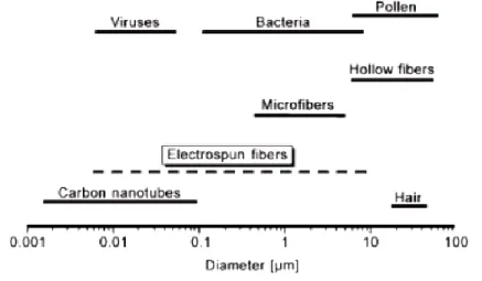
Moreover, electrospun nanofibers can be produced in a wide range of diameters small enough to be compared with nanoscale objects of biological systems such as proteins, viruses and bacteria. A comparison of nanofibers diameter with other nanoscale objects is illustrated Fig. 2-4.
Figure 2-4: Comparison of the diameter of electrospun nanofibers with nanoscale biological and technological objects (Greiner and Wendorff 2007)
2.2.2.1 Description of the electrospinning technique
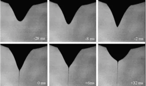
In the electrospinning process, a high voltage is applied between a syringe filled with polymer solution and a collector mounted at a fixed distance. The resulting powerful electric field causes a pendant drop of polymer solution to be electrified, and the induced charges distributes over its surface. At this stage, two forces act on the droplet; repulsive force between the surface charge and coulombic force exerted by the external electrical field on the droplet. Further increase in the applied voltage deforms the drop into a conical shape commonly known as Taylor cone (Reneker and Chun 1996). Evolution of the pendant droplet at the tip of a needle by increasing the applied voltage is displayed in Fig. 2-5. If higher voltages are applied, the strength of the applied electrical field can overcome the surface tension of the polymer solution and a liquid jet is ejected from the deformed drop at the nozzle (Fig. 2-5) (Reneker, Yarin et al. 2000; Koombhongse, Liu et al. 2001; Han, Yarin et al. 2008; Reneker and Yarin 2008). This electrical jet then undergoes a stretching and whipping process towards the counter electrode on the collector. During this step, the liquid jet is elongated and the solvent is evaporated, leading to a large reduction in the jet
diameter from hundreds of micrometers to as small as tens of nanometers, and is then deposited with high velocities of 1-10 m/s on the collector (Reneker, Yarin et al. 2000; Yarin, Koombhongse et al. 2001; Yarin, Koombhongse et al. 2001; Thompson, Chase et al. 2007; Han, Yarin et al. 2008; Reneker and Yarin 2008).
Figure 2-5: Evolution of Taylor Cone by increasing the electrical field (Reneker and Yarin 2008).
The charged fiber often deposits as a randomly oriented, non-woven mat on the collector. Depending on the polymer solution used and the electrospinning conditions, other morphologies such as beads, beaded fibers or ribbon-type fibers can be obtained instead. Typical examples of these morphologies are shown in Figs. 2-6 to 2-8.
Figure 2-6: SEM image of beads produced by electrospinning of 1 wt% PEO (900 kDa) solution in water, the horizontal edge of image is 20 μm long. (Fong et al. 1999).
Figure 2-7: SEM image of beaded fiber morphology obtained from electrospinning of 2.5 wt% PEO (900 kDa) solution in water, the horizontal edge of image is 20 μm long (Fong et al. 1999).
Figure 2-8: SEM image of ribbon fiber morphology prepareded by electrospinning of 10% Poly (etherimide) (Theron et al. 2004).
2.2.2.2 Electrospinning development
Electrical liquid droplets and jets have been studied for more than hundred years. These works provide the fundamental basis for electrospraying and electrospinning. Stability of the jet is the main difference between these two processes. In electrospraying the electrical jet breaks into droplets due to capillary instability, but if there is enough entanglements in the fluid, it will be stabilized and make a continued jet in the form of thin filaments resulting in the electrospinning
process (Ramakrishna, Fujihara et al. 2005). Cooley (Cooley 1902; Cooley 1903) and Morton (Morton 1902) issued the first patents on the electrostatic spinning of polymer solutions. They used cellulose nitrate in acetone and proposed a method of dispersing fluids that is similar to electrospinning and spraying. From 1934 to 1944, Formhals (Formhals 1934; Formhals 1943) published a sequence of patents on an improved version of the electrospinning process and apparatus. Sir Taylor in 1960s (Taylor 1964) fundamentally investigated the deformation of a droplet into a conical geometry in an electrical field. Baumgarten (Baumgarten 1971) produced acrylic fibers with diameter less than 1 µm from DMF solution. He studied the effect of solution viscosity (concentration) and electrical field on the diameter of fibers. Larrondo and Manley (Larrondo and Manley 1981) produced electrospun fibers of PE and PP by melt electrospinning. Although these studies prepared the basics for the electrostatic spinning process, the present knowledge is mainly due to more recent work, especially the ones carried out in the last 10-15 years. From 1993 to 1996, Reneker and coworkers reexamined the process to produce nanofibers (Doshi and Reneker 1995; Reneker and Chun 1996) and they coined the term “electrospinning” instead of electrostatic spinning for the first time. Recent scientific attempts also contributed well toward better understanding of electrospinning and its effective parameters to develop industrial applications. Consequently, nowadays research on electrospun nanofibers is not restricted only to academia, but also different companies such as Donaldson, Elmarco, Finetex Tech and Amsoil Ea are involved in the development/production of nanofibrous products for superior performance for several industrial applications and nanofiber production equipments.
2.2.2.3 Mechanism of electrospinning
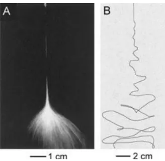
Electrospinning looks simple but a closer inspection shows that this process is very complex. For instance, the jet only follows a direct path for a certain distance and after that, it changes its behavior considerably. The jet moves laterally and then splays into a number of jets, forming a cone shape towards the collector. Figure 2-9 shows a typical photograph of a jet during the electrospinning process on its way from a needle to the collector, taken at two different capture times (Shin, Hohman et al. 2001).
Figure 2-9: Photographs of a jet of PEO solution during electrospinning with two different capture times: A) 1/250 s, B) 18 ns (Shin, Hohman et al. 2001).
Before 1999, splitting or splaying the electrified jet due to the repulsion forces between surface charges was thought to be the main reason of nanofiber formation during the electrospinning process (Reneker and Chun 1996; Li and Xia 2004). However, more experimental observations showed that the thinning of a jet by the electrospinning process is mainly caused by the bending instability associated with the electrified jet (Reneker, Yarin et al. 2000; Yarin, Koombhongse et al. 2001). This concept was concluded further by experiments done by Yarin et al. (Yarin, Koombhongse et al. 2001; Yarin, Koombhongse et al. 2001), and Shin et al. (Shin, Hohman et al. 2001) in 2001. By using high-speed photography, they found that the conical envelope in the electrospinning jet contains only a single, rapidly bending or whipping thread (Fig.2-9B), even though it appears that the cone shaped region is composed of multiple jets. In some cases, splaying of the jet is also observed, but it is not the dominant process during electrospinning (Reneker, Yarin et al. 2000; Shin, Hohman et al. 2001; Yarin, Koombhongse et al. 2001; Yarin, Koombhongse et al. 2001; Li and Xia 2004). The frequency of whipping is so high that conventional photography cannot properly show what happens exactly, giving the impression of jet splaying into multiple jets toward the collector (Li and Xia 2004).
2.2.3 Applications of polymeric nanofibers
The special geometry of electrospun nanofibers makes them attractive options for various applications in the field of nanostructured materials and design. Figure 2-10 illustrates the potential applications of polymer nanofibers in different fields.
Figure 2-10: The diversity of application areas proposed for electrospun nanofibers (Huang, Zhang et al. 2003).
Nanofibrous mats have a high surface area to mass ratio (40-100 m2/g). This unique characteristic is ideal for various membranes applications such as:
Chemical membranes for removal of toxic products
Protective clothing against chemical, biological or environmental attacks
Ultrafine filters for air filtration in medicine, military devices, food processing and electronic industries to absorb tiny particles
Two third of U.S. patents published on nanofibers are related to biological and medical applications. However, the first completely industrialized application of nanofibers was introduced in filtration due to its huge market. Electrospun mats as filter media provide advantages of high filtration efficiency, absorbance of fine particles and low air resistance resuling in lower pressure drop. Nanofibers are also attractive materials for nano sensor applications because their high specific area provides the ability to absorb or react rapidly with low levels of chemicals.
2.3 Nanofibrous chitosan membrane
There has been a growing interest for the fabrication of chitosan membranes with micro and nanoporous morphologies recently. Such chitosan mats can not only present the specific physicochemical properties of chitosan but can also benefit from the physical characteristics of microporous membranes. Several methods have been used to fabricate porous chitosan structures such as phase separation (Gu, Xue et al. 2001; Mi, Wu et al. 2003), phase inversion (Li, Gu et al. 1999; Mi, Shyu et al. 2001) and selective dissolution (Zeng, Fang et al. 2004). After successful development of the electrospinning technique to fabricate polymeric nanofibers, many researchers tried to employ this method to prepare chitosan microporous mats (Duan, Dong et al. 2004; Min, Lee et al. 2004; Ohkawa, Cha et al. 2004; Ohkawa, Minato et al. 2006). Fabrication of chitosan-based nanofibers in the form of non-woven mats is very desirable, as it can provide novel possibilities to develop applications of chitosan in various fields (Torres-Giner, Ocio et al. 2008). However, it was soon found that chitosan electrospinning is challenging. It is more likely due to its polycationic nature in solution, rigid chemical structure and specific inter and intra-molecular interactions (Duan, Dong et al. 2004; Li and Hsieh 2006; Desai, Kit et al. 2008). Formation of strong hydrogen bonds prevents the free movement of polymeric chain segments exposed to the electrical field, leading to jet break up during the process (Geng, Kwon et al. 2005; Li and Hsieh 2006; Desai, Kit et al. 2008). Additionally, the repulsive forces between ionic groups on the polymer molecules is expected to hinder the formation of sufficient chain entanglements to allow continuous fiber formation during jet stretching, whipping and bending, generally resulting in nanobeads instead of nanofibers (Min, Lee et al. 2004). In fact, it has been
shown on many occasions that sufficient chain entanglement in polymer solution is crucial for a successful electrospinning process (McKee, Wilkes et al. 2004; McKee, Park et al. 2005; Shenoy, Bates et al. 2005; Woerdeman, Shenoy et al. 2007).
2.3.1 Electrospinning of chitosan
In spite of all aforementioned difficulties in electrospinning of chitosan, its valuable properties and prospective applications are attractive enough to convince different research groups to work on this subject. Since 2004 several methods and approaches have been used with varying degrees of success to prepare electrospun nanofibers based on chitosan.
2.3.1.1 Electrospinning of neat chitosan
Neat electrospun chitosan nanofibers have been prepared by dissolving chitosan in trifluoroacetic acid (TFA) (Ohkawa, Minato et al. 2006) and its mixtures with dichloromethane (DCM) and trichloromethane (TCM) (Schiffman and Schauer 2007). TFA forms stable salts with the amino groups of chitosan which can efficiently hinder the intermolecular interactions between chitosan chains and facilitate electrospinning (Ohkawa, Minato et al. 2006). A highly concentrated aqueous acetic acid solution (80-90%) was also reported by some research groups as another successful solvent for the fabrication of neat chitosan nanofibers, using chitosan grades with DDA of 54 (Geng, Kwon et al. 2005) and 75-85% (Homayoni, Ravandi et al. 2009). It is believed that decreasing the surface tension of the solution by increasing the acetic acid content can help the electrospinnability of chitosan (Geng, Kwon et al. 2005). Applications of electrospun chitosan nanofibers using TFA-based solvents are however limited, as the prepared membranes can easily dissolve in neutral and weak basic aqueous solvents (Sangsanoh and Supaphol 2006), due to the high solubility of the TFA-chitosan salt residues. Additionally, working with toxic and harmful solvents and the possible presence of their residues in the final membranes always raise major concerns.
2.3.1.2 Electrospinning of chitosan blends with synthetic polymers and proteins
Blending chitosan with materials that facilitate its processing is another approach to make chitosan electrospinnable. The co-spinning agent should have excellent fiber forming
characteristics in order to create entanglements and physical bonds with chitosan, and act as a carrier in the electrospinning process. Various synthetic polymers have been successfully blended with chitosan to produce chitosan-based composite nanofibers such as: polyethylene oxide (PEO) (Bhattarai, Edmondson, et al. 2005; Desai, Kit et al. 2008; Klossner, Queen et al. 2008), polyvinyl alcohol (PVA) (Li and Hsieh 2006; Jia, Gong et al. 2007; Zhou, Yang et al. 2008), polylactic acid (PLA) (Ignatova, Manolova et al. 2009), nylon-6 (Zhang, Wu et al. 2010) and polycaprolactone (PCL) (Zhang, Venugopal et al. 2005). Moreover, chitosan blends with proteins such as: silk fibroin (Cai, Mo et al. 2010; Sionkowska 2011), zein (Torres-Giner, Ocio et al. 2009) and collagen (Mi, Shyu et al. 2001) have been electrospun productively. Generally the content of the co-spinning agent varies from 20 to 80 wt%. The presence of this second phase can however affect the properties of the nanofibers by decreasing the chitosan content located at the surface. This influences properties such as biocompatibility and mechanical integrity, and may be hard to rectify by an extraction process.
2.3.1.3 Co-axial electrospinning of chitosan
The co-axial electrospinning method provides an alternative and effective way of fabricating chitosan-based nanofibers. In this technique, two different solutions are spun simultaneously through a spinneret composed of two co-axial capillaries to produce core-shell structured nanofibers. Sun et al. (Sun, Zussman et al. 2003) and Yu et al. (Yu, Fridrikh et al. 2004) employed co-axial electrospinning to prepare nanofibers from polymer solutions with limited electrospinnability. They co-electrospun these solutions as the core material, with a readily electrospinnable solution as the shell layer to make core-shell nanofibers of the two components. Only Ojha et al. (Ojha, Stevens et al. 2008) used co-axial electrospinning technique to prepare chitosan nanofibers. They fed PEO as a template sheath for the chitosan core in a co-axial electrospinning set up. This leads to a two-step process, as the PEO shell layer should be removed by water washing to expose the chitosan nanofibers.
2.3.2 Applications of electrospun chitosan nanofibers
Electrospun chitosan microporous structures have been sucessfully used for many applications in recent years. Among them the followings were more promising:
Supports for enzyme immobilization (Ye, Xu et al. 2006; Wang, Wan et al. 2009)
Anti-bacterial films (Ignatova, Starbova et al. 2006; An, Zhang et al. 2009; Son, Yeom et al. 2009)
Membranes for metal ions removal (Desai, Kit et al. 2008; Desai, Kit et al. 2009; Haider and Park 2009; Horzum, Boyaci et al. 2010)
Drug delivery systems (Ignatova, Manolova et al. ; Jayakumar, Menon et al. 2010; Jayakumar, Prabaharan et al. 2010)
Tissue engineering (Subramanian, Vu et al. 2005; Yang, Jin et al. 2008; Zhang, Venugopal et al. 2008; Wang, Itoh et al. 2009; Cooper, Bhattarai et al. ; Prabhakaran, Ghasemi-Mobarakeh et al. 2011)
Wound healing dressings (Chen, Chang et al. 2008; Zhou, Yang et al. 2008; Ignatova, Manolova et al. 2009; Cai, Mo et al. 2010; Kang, Yoon et al. 2010)
2.4 Phase behavior of polymer solutions
Phase separation behavior of polymer solutions is of great interest in both scientific and industrial point of view. (Bae, Lambert et al. 1991; Dormidontova 2002; Hammouda, Ho et al. 2004; Shetty and Solomon 2009) Aqueous PEO solutions exhibit an inverse solubility-temperature relationship that leads to a phase separation upon heating. Therefore, a low critical solution temperature (LCST) that depends on the molecular weight is observed for high molecular weight PEO grades in water. Such extraordinary properties are seen only in highly polar systems that have strong molecular interactions such as hydrogen bonding.(Polic and Burchard 1983; Bae, Lambert et al. 1991; Fischer and Borchard 2000)
Aqueous acidic solutions of chitosan also exhibit great solubility, similarly to aqueous PEO solutions, due to the presence of strong hydrogen bonds between the solvent and the polymer owing to the presence of hydroxyl, acetylamine and amino groups on the chitosan chain.
Therefore, the occurrence of an LCST in chitosan solutions is expected.(Bae, Lambert et al. 1991; Dormidontova 2002)
Therefore, having clear knowledge about the phase behaviour and miscibility of solutions of chitosan and PEO and their blends is of crucial importance, as any phase separation occurring during the electrospinning process greatly changes the morphology and properties of the final products.
Several methods have been used to study the onset of phase separation in polymer systems. Simple visual observation of turbidity (Fischer, Borchard et al. 1996), thermo-optical analysis (TOA) (Bae, Lambert et al. 1991), light scattering (Polic and Burchard 1983; He, Liu et al. 1991; Shetty and Solomon 2009) and small angle neutron scattering (SANS) (Hammouda, Ho et al. 2002; Hammouda, Ho et al. 2004) are frequently used to determine the early stages of liquid-liquid phase separation in polymer solutions.
Rheometry represents a powerful tool to study the phase behaviour of polymeric systems. Near the phase separation temperature, the linear viscoelastic response is influenced by the critical concentration fluctuations and exhibits a thermorheological complexity, i.e. enhancement of elasticity in the vicinity of phase separation.(Kapnistos, Hinrichs et al. 1996; Niu and Wang 2006) Ajji and Choplin(Ajji and Choplin 1991) quantified this phenomenon for polymer blends by extending the mean field theories of Fredrickson and Larson (Fredrickson and Larson 1987) developed for copolymers. It was shown that this approach can determine both the spinodal (Kapnistos, Hinrichs et al. 1996; Niu and Wang 2006; Yeganeh, Goharpey et al. 2010) and binodal (Sharma and Clarke 2004; Niu and Wang 2006) temperatures by carrying out a dynamic temperature sweep test on the blend and tracking the evolution of rheological material functions and . This method was successfully employed for different polymer pairs and the obtained data agreed well with that from other techniques such as optical microscopy (Ajji, Choplin et al. 1991; Yeganeh, Goharpey et al. 2010), light scattering (Vlassopoulos, Koumoutsakos et al. 1997) and inverse gas chromatography. (Bousmina, Lavoie et al. 2002)