HAL Id: hal-01276631
https://hal.archives-ouvertes.fr/hal-01276631
Submitted on 19 Feb 2016
HAL is a multi-disciplinary open access
archive for the deposit and dissemination of
sci-entific research documents, whether they are
pub-lished or not. The documents may come from
teaching and research institutions in France or
abroad, or from public or private research centers.
L’archive ouverte pluridisciplinaire HAL, est
destinée au dépôt et à la diffusion de documents
scientifiques de niveau recherche, publiés ou non,
émanant des établissements d’enseignement et de
recherche français ou étrangers, des laboratoires
publics ou privés.
Integration of UML in human factors analysis for safety
of a medical robot for tele-echography
Jérémie Guiochet, Bertrand Tondu, Claude Baron
To cite this version:
Jérémie Guiochet, Bertrand Tondu, Claude Baron. Integration of UML in human factors analysis
for safety of a medical robot for tele-echography. IEEE/RSJ International Conference on
Intelli-gent Robots and Systems, IntelliIntelli-gent Robots and Systems for Human Security, Health, and
Pros-perty IROS 2003, Las Vegas, USA, IEEE/RSJ, Oct 2003, Las Vegas, United States. pp.3212-3217,
�10.1109/IROS.2003.1249651�. �hal-01276631�
Integration of UML in Human Factors Analysis for Safety of a
medical robot for tele-echography
Jérémie GUIOCHET
GRIMM-ISYCOM / LESIA University of Toulouse II
31100 Toulouse, France [email protected]
Bertrand TONDU and Claude BARON
LESIA INSA-DGEI 31077 Toulouse, France [email protected]
Abstract— For new robot applications, as medical robots,
safety has became a major concern. The human sharing the working area with the robot led to integrate the field of human factors in the development. Hence, the human component has to be integrated in the early steps of the development process. Regards to the complexity of today’s robotic application, and to the requirements of a teamwork, we choose UML as the language. This paper focuses on the UML modeling contribution to the human factors analysis of a medical robot. A first section presents the function allocation and task analysis step, and a second section deals with human error. Each section is illustrated by a case study of a system for robotic tele-echography (ultrasound scan examination).
I. MOTIVATIONS
Today, as many new application areas for robotic sys-tems emerge, including medical robots, safety is becoming critical [5]. Robots can have a close interaction with pa-tients and medical specialists. In this context, for medical robots as Robodoc (ISS, Inc., USA), AESOP (Computer Motion, Inc.,USA), or daVinci (Intuitive Surgical, Inc., USA), safety is the essential requirement for commer-cialization [1]. This concept, defined for industrial robots as the prevention of damage to the robot itself and its environment, and particularly the human component [6], can now be defined as the property of a medical robot to be "free from unacceptable risk" [10]. Therefore it’s necessary to reduce the risk to an acceptable level with a complete risk management activity [11]. The integration of human factors in this activity is still in work [8], [9]. But it’s obvious that the interaction between the human and the technology in a medical robotic system, plays a major role in safety. Therefore, the human component have to be integrated at the early stages of the development process. Those activities are based on a system model. Ideally, the system definition is modeled formally, but the use of formal methods in industrial development of safe systems is still rare. A significant barrier is that many formal languages and formal analysis techniques are unfamiliar and difficult to understand and to apply for engineers. Developers must also integrate medical specialists require-ments, and explain them the whole system definition. For these reasons, existing techniques must be considered. UML (Unified Modeling Language) notation fulfill these
claims, and is now a standard in system and software engineering. It’s also well adapted to robotic systems [4]. In scope of the TER project [22], a system for robotic tele-echography, we have studied the relationships be-tween the main activities of a human factors analysis and a system definition in UML. Human factors as an overall discipline covers a wide range of areas related to integration of humans within work systems. We focus on those that are core to human factors, and that have an important relation with system definition and safety. A first step is to analyze tasks and determine function allocation which are two main activities of human factors engineering. A second step concerns the analysis of human error which is the major activity of human reliability assessment.
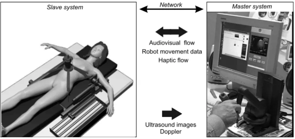
Each section is illustrated by a case study of a system for Robotic Tele-Echography (TER)[22]. TER is a tele-robotic system designed and developed by a French con-sortium composed of universities, hospitals and industrial companies. The slave robot is tele-operated by an ex-pert clinician who remotely performs the ultrasound scan examination. A virtual probe is mounted on the master interface device. The real probe is placed on the slave robot end-effector. We will focus on the computer control system of the slave site, where safety is critical.
II. FUNCTIONALLOCATION ANDTASKANALYSIS
The function allocation aims at determining the dis-tribution of work between human actors and machines. It is particularly important to define non ambiguous and consistent tasks for humans who are using the robot. Task analysis is conducted to identify the details of specified tasks, including the required knowledge, skills, attitudes, and personal characteristics required for successful task performance.
These activities are usually performed with different algorithms. The allocation should be iterative and can follow algorithms as in [14, pp.231-236], [2] and [16]. Through this description of function allocation, modeling furnish basis for task analysis. One of the difficulties is to model those allocations and to integrate them to system modeling. The purpose of this paper is not to present algorithms for those activities, but to analyze how
Patient Diagnose Realize Ultrasound Scan
Patient Management Probe Management Specialist
Fig. 1. Use case diagram: global view of ultrasound scan examination
UML help in modeling the specification of the function allocation and the definition of task analysis.
A. General Scenario
The first step is to describe the general scenario of an usual ultrasound scan examination. The UML use case
diagram in figure 1 presents the main use cases during this
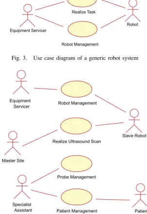
task. This diagram belongs to the business modeling (as defined in [12]). The business is here the real ultrasound scan examination. Business modeling permits to increase the understanding of the business and facilitate com-munication about the business [7], particularly between engineers and doctors. Based on this diagram, the TER system is later integrated in the requirement modeling in the next diagrams. In the TER project, experts have studied the ultrasound scan examination and particularly the use case Realize Ultrasound Scan, to determine all the interactions between the doctor manipulating the probe, and the patient (particularly pressures and movements on the patient’s body which are critical for safety). This leads to the choice of a parallel robot structure (see figure 2) which is different to a serial robot structure (like a robot arm). The main safety criteria was to limit the work envelope and limit the collisions (which are well-known with robot arms). The difficulty of modeling the working area (i.e. the patient’s body), leads to the choice of a compliant slave robot, with an actuation by intrinsically compliant artificial muscles [21]. The other use cases have also be studied to determine the architecture of the TER system. For example, the use case Patient Management, contains scenarios of communication between the patient and the medical expert which are essential. This led to choose a bi-directionally visioconference subsystem. The other business that will be integrated is the use of a robot. This led to the generic use case diagram on figure 3. A new actor is specified on this diagram: the Equipement
Servicer, who is in charge of the Robot Management and
involved in the task achievement.
Robot
Robot Management Realize Task
Equipment Servicer
Fig. 3. Use case diagram of a generic robot system
Realize Ultrasound Scan
Specialist
Assistant Patient Management Probe Management Patient Robot Management Master Site Equipment Servicer Slave Robot
Fig. 4. Use case diagram of the TER slave site
B. From actual echography to robotic echography
An overview of the TER system is presented on figure 2. This led to use and modify specifications of previous use cases. Indeed, based on the use case diagrams of figure 3 and figure 1, we model the slave site on figure 4. On this diagram new actors are identified. First UML diagrams (use case and object diagrams) show all the interactions between actors and the system, but also between actors themselves. An actor characterizes an outside user or related set of users who interact with the system [3]. It is possible for an actor to be a human user (like in figure 1) or an external system. This is really useful in socio-technical systems, and particularly in the TER project. Indeed, such a modeling allows the interactions to be handled for safety studies. We choose to represent two external systems as actors: the Master Site and the
Robot. The Master Site replaces the actor Specialist (see
figure 1) who is in the charge of realizing the examination. It is important to observe that the use case Diagnose has also disappeared.
This diagram shows a first allocation of tasks between actors according to the medical domain. Tasks can be described with collaboration or sequence diagrams for each use case. However, on this diagram, the boundaries of the computer control system are not defined. We defined
Slave system Network Master system
Audiovisual flow Robot movement data
Ultrasound images Doppler Haptic flow
Fig. 2. TER system overview
the TER Control System as all the machine parts (computer control system, actuators, sensors, monitors, etc.) but without the physical structure of the robot. In order to specify requirements, it is important to define whether each use case belongs to the system or not. For example, the use case Robot Management includes tasks such as maintenance operations. This fault prevention operation (preventive maintenance) can be entirely independent of the TER system or may be assisted by the system (for example by monitoring the use time of critical units).
Patient Management is a set of scenarios that can be
clean patient, position patient, or monitor patient during operation. These use cases imply a collaboration between cognitive ergonomists, medical specialists and requirement engineers to determine, for each task, how the system can help the actors to perform the task, make decisions, diag-nose or act. Again the models have to be understood by all the participants of the development process (analysts, designers, etc.).
C. TER Control System boundaries
The determination of the system boundaries is a funda-mental step of requirements analysis, and is entirely linked with the definition of human tasks. In this step, it should be determined which of the requirements are system require-ments, which are requirements for the operational pro-cesses associated with the system and which requirements should be outside the scope of the system [20]. Based on figure 4, we have chosen use cases that belong to the computer control system for the TER slave robot. Figure 5 models the computer control system use cases where a new actor is specified in the class diagram presented in figure 6: Operator inherits from the Equipment Servicer and the Specialist Assistant. Some previous use cases as
Visioconference Management (not shown for readability)
and Probe Management have been removed from this use case diagram (figure 5) because they don’t belong to or have any interaction with the computer control system.
TER Control System
Operator
Patient Management Robot Management
Install / Init Control System <<include>> Calibrate Controller <<include>> <<include>> Patient Master Site
Realize Ultrasound Scan
Slave Robot
Fig. 5. Use case diagram with Control System boundaries
Specialist Assistant Equipment Servicer TER control system Slave robot Patient Move probe on Operator Installing, monitoring
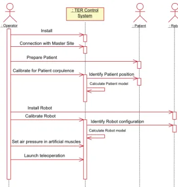
On sequence diagram presented in figure 7, the main scenario of the installation of the whole system is pre-sented. We present this diagram because most of the interactions between human and technology appear during this scenario (during the use case Realize ultrasound scan, human tasks are less numerous). Such diagram help in describe tasks that humans have to do. For instance the
Operator have to Prepare Patient, which can be extend in
position the patient, put ultrasound scan gel on patient’s body, give information to the patient, monitor the patient, etc. Therefore, this diagram and some refinements help in represents all the tasks.
This notation of tasks is also useful to determine an order of actions, which can be essential for safety. In-deed, the sequence of actions presented on figure 7 have been determined according to functional requirements and safety requirements. For instance, Connection with master
site have been placed before all the installation procedures
in order to minimize the waiting time (connection can be long) of the patient with the robot placed on her/his body (that can create a psychological trouble). Another example is the action Set air pressure in artificial muscles coming after all installations and calibrations. Without any air pressure in artificial muscles, the robot system is safe and all the installations and checks can be done safely.
On the same diagram it is also important to study interlocks between tasks. The calibration of the controller depends on the patient corpulence, and this factor influ-ence also the robot settings (for example the length of the cables connected from muscles to the slave robot, see figure 2). Hence, it is important to calibrate the controller, first according to the patient body, and then to the robot settings. The order of those actions presented with sequence diagram is easily readable by non expert modeling.
These models which are essential in a safety critical project, can directly be used for different safety-dependent tasks: writing of a user-guide (using the sequence dia-grams), specification and design of the Human-Machine Interface (HMI) and furnish models for the specification of the system. It is important to note that in such robot systems, HMI includes the robot-human interface (control panels, teach pendant, computers, etc.) but also the robot itself (in the TER project the slave robot is always in contact with the patient’s body).
III. HUMANERRORANALYSIS
The other main activity of a human factors study, is the analysis of human error: a failure of a human to do a specified action, which results in undesirable outcomes. The aim of this step is to reduce the undesirable actions, their propagation and their outcomes. It leads to the specification of new requirements, re-design and documentation production. The complexity of human error
: Operator
: TER Control System
: Patient : Robot
Prepare Patient
Calibrate for Patient corpulence
Identify Patient position
Identify Robot configuration Calibrate Robot
Calculate Patient model
Calculate Robot model
Install
Set air pressure in artificial muscles
Launch teleoperation Install Robot Connection with Master Site
Fig. 7. Sequence diagram of installation of the whole system
Interface design proposals Scenarios from use cases Human error and performance models Elaborate scenarios description Error identification and analysis New requirements & re-design & documentation
Fig. 8. Structure of human error analysis method
classification and cognitive theory [18] usually lead to the use of design checklists and guidelines [15]. Human error analysis methods are also often based on experimentation, simulation, and on human reliability analysis [13]. But for innovating projects, it is really difficult to get information on experience, incident and accident reports. Moreover, guidelines are not sufficient for innovative projects as medical robots [23]. For instance, we found nothing on medical robots. Thus, we had to develop our own accident scenarios. We notice that a human error is linked with a use case because it appears during a scenario of use. So the description of the error can be modeled with a sequence diagram. It is a scenario of a use case with an erroneous
message generated by a human actor. Then, a number of
models, theories and collections of empirical data about human performance and human error can be useful in deciding which scenarios it will be important to analyze [19]. This analysis process is presented in figure 8 adapted from THEA [17], a method for human error analysis.
then on the requirement models (as explained previously). The business modeling leads to identify errors linked with social interaction whereas the requirement modeling identifies errors during the use of the system, directly linked with human-machine interfaces. For instance, based on the sequence diagram in figure 7, different errors can be identified:
• Omission, non execution of an expected action: the
operator forget to launch Connection with master site
• Realization error:
– Bad execution of an expected action: the
opera-tor place the patient in a wrong position
– Execution of an action at a wrong instant: the
operator do the Set the air pressure in artificial
muscles before position patient
– Execution of several actions in a wrong
se-quence: the operator can change the order of the installation and calibration.
• Unknown or unplanned actions: the patient try to
catch the robot.
For each identified error it is possible to describe the scenario with a sequence diagram but also to describe effects and to present corrective measures (interlocks, checks, use modification, etc.). In this paper we don’t present a sequence diagram for an error analysis, because figure 7 need to be refined in order to show how an error can change an actor or an object state. For instance, a bad calibration of the patient will generate a wrong patient
model, that can be a software component included in the
TER Control System. More refined diagrams can then present how a wrong patient model can be a source of risk for patient.
Later, for each HMI proposal, all the potential errors have to be analyzed in the same way. In the TER project, the operator is in charge of calibrating the robot controller in order to calculate robot and patient models (see fig-ure 7). The proposal interface for this scenario is the use of a 3-D position sensor manipulated by the operator. The use of such an interface can produce errors. Based on the sequence diagram, we can determine for each message how it is possible to reduce errors (supervision of the system and validation of the calculated models) and also produce a documentation for the procedure. For the TER system, there are three main HMI on the slave site: a computer, a power control panel and the robot itself. The human error analysis has to consider how the human can fail in interacting with those HMI during a use case scenario. For example, it is important to identify what will happen if the operator pushes the wrong button during a use case. Again, this implies the use of sequence diagrams. In order to identify scenarios and system responses to the errors, it is useful to use a state diagram (Harel’s statecharts) to model the external black box behavior
to indicate in which state the system is when the error happens. A state diagram can also be useful to identify the effects of a human error on the system. In order to be concise we do not present the state diagram which require place and explanation for the semantic.
As presented here, it is possible to describe human error effects on system with sequence diagrams. But today there isn’t any tools to integrate errors in the UML models, the description remains qualitative. Moreover, during require-ments analysis, models are not enough refined to identify the error propagation from humans to computer control system. This can be done later, and particularly during risk management activities. Indeed during risk analysis, failures and their effects are analyzed. And it is possible to integrate human errors in techniques as Failure Modes Effects and Critically Analysis and Fault Tree Analysis.
IV. CONCLUSION
Medical robots belong to safety-critical systems, and human factors studies are a major concern during safety analysis of such systems. In order to guarantee consistency of information between the different entities (engineers, doctors, etc.) throughout the development process and particularly during the requirements analysis, we proposed to use the object-oriented language UML.
Throughout the human factors analysis two major ac-tivities can be identified. The power of UML in modeling socio-technical systems, and the different diagrams, used in the business modeling and the requirement modeling, help to model function allocation and contribute to the task analysis. We also use those models to identify and analyze human errors. This point needs to be further developed, especially for innovations where it is difficult to apply historical data or experience. This human factors study have mainly been performed during the requirements spec-ification. Moreover in an iterative development process, this study have been updated several times and at different steps of the development process.
A further work concerns the risk management. This analysis, widely used in different safety-critical domains, and one of the essential requirements for certification, is based on models of the system. Analytical methods, like Failure Modes Effects and Critically Analysis and Fault Tree Analysis can be combined and are today widely used in robotic and medical field. Studies have to be held to highlight relationships between UML notation, FMECA tables and FTA trees. We are now combining those techniques in the TER project.
V. REFERENCES
[1] 93/42/EEC. Council directive of the 14th of june 1993 concerning medical devices. Journal officiel des Communautés européennes (JOCE) N◦L169, 1993.
[2] D. Beevis, R. Bost, B. Döring, E. Nordø, F. Oberman, J-P. Papin, H. Schuffel, and D. Streets. Analysis tech-niques for man-machine systems design. Technical Report AC/243(Panel 8)TR/7, NATO, Canada, 1994. [3] G. Booch, J. Rumbaugh, and I. Jacobson. Unified
Modeling Language Users Guide. Addison Wesley
Longman, 1999.
[4] L. Caroll, B. Tondu, C. Baron, and J.C. Geffroy. Comparison of two significant development methods applied to the design of real-time robot controllers. In
IEEE International Conference on Systems, Man and Cybernetics (SMC’98), La Jolla, USA, pages 3394–
3399, October 1998.
[5] B. Davies. Safety of medical robots. ICAR’93, pages 311–313, 1993.
[6] B.S. Dhillon. Robot Reliability and Safety. Springer-Verlag, 1991.
[7] H.E. Eriksson and M. Penker. Business modeling
with UML: business patterns at work. John Wiley
and Sons, Inc., 2000.
[8] Food and Drug Administration. Medical device use-safety: incorporating human factors engineering into risk management. Technical report, U.S. Departe-ment of Health and Human Service, 2000.
[9] HSE. Proposed framework for addressing human factors in IEC 61508. Technical Report 373/2001, Health and Safety Executive, UK, 2001.
[10] ISO/IEC Guide 51. Safety aspects - Guidelines for their inclusion in standards. International Organiza-tion for StandardizaOrganiza-tion, 1999.
[11] ISO 14971. Medical devices - Application of risk management to medical devices. International Orga-nization for Standardization, 2000.
[12] I. Jacobson, G. Booch, and J. Rumbaugh. The
Unified Software Development Process. Addison
Wesley Longman, 1999.
[13] B. Kirwan. Human error identification in human re-liability assessment. Part I: Overview of approaches.
Applied Ergonomics, 23(5):299–318, 1997.
[14] J-C. Laprie, J. Arlat, J-P. Blanquart, A. Costes, Y. Crouzet, Y. Deswarte, J-C. Fabre, H. Guillermain, M. Kaâniche, K. Kanoun, C. Mazet, D. Powell, C. Rabéjac, and P. Thévenod. Dependability
hand-book (in French). Cépaduès - Éditions, Toulouse,
France, 1995.
[15] N.G. Leveson. Safeware - System safety and
com-puters. Addison-Wesley, University of Washington,
1995.
[16] M. Mersiol, C. Mazet, H. Guillerman, and H. Wae-selynck. Human dependability in complex system: an issue of task consistency and task allocation.
International Conference on Probabilistic Safety As-sessment and Management (PSAM’4), 4:2693–2698,
September 1998.
[17] S. Pocock, B. Fields, M. Harrison, and P. Wright. THEA - A reference guide. Technical Report 336, University of York Computer Science, 2001. [18] J. Reason. Human Error. Cambridge University
Press, 1990.
[19] J. Rushby. Modeling the human in human factors.
SAFECOMP01, pages 86–91, 2001.
[20] I. Sommervile and P. Sawyer. Requirements
engi-neering : a good practice guide. John Wiley and
Sons, Inc., 1997.
[21] B. Tondu and P. Lopez. Modeling and control of McKibben artificial muscle robot actuators. IEEE
Control Systems, 20(2):15–38, 2000.
[22] A. Vilchis, P. Cinquin, J. Troccaz, A. Guerraz, B. Hennion, F. Pellissier, P. Thorel, F. Courreges, A. Gourdon, G. Poisson, P. Vieyres, P. Caron, O. Mérigeaux, L. Urbain, C. Daimo, S. Lavallée, P. Arbeille, M. Althuser, J-M. Ayoubi, B. Tondu, and S. Ippolito. TER: a system for Robotic Tele-Echography. Lectures Notes in Computer Science,
Medical Image Computing and Computer-Assisted Intervention (MICCAI’01), pages 326–334, 2001.
[23] P. Wright, B. Fields, and M. Harrison. Deriv-ing human-error tolerance requirements from tasks.
IEEE International Conference on Requirements En-gineering (ICRE’94), 1:462–467, 1994.